INGAL Ezy-Guard Smart User manual
www.ezyguard.com
Release 07/22
Product Manual

2
Release 07/22
Roadside Safety Barrier
1.0 Introduction
Introducing Ezy-Guard Smart, a
member of the Ezy-Guard family, the
next generation steel guardrail barrier
providing superior motorist safety and
more metres of barrier for your dollar.
Ezy-Guard Smart is crash tested to
the latest performance standard
distinguishing it from the existing
Australian public domain guardrail
barriers.
The Z-post prole shields post edges
from vulnerable road users and
provides sectional strength when
driving through dicult conditions.
An Ezy-Carriage is used to secure the
w-beam rails to the posts eliminating
the requirement for blocking pieces
and rail stiening plates. This unique
connection provides a soft ride-down
for the occupants and smooth vehicle
containment and redirection.
2.0 Specications
Ezy-Guard Smart Z-Post Length: 1,600mm
Ezy-Guard Smart Z-Post Mass: 12.3kg
Ezy-Guard Smart System Mass: 18.6kg per metre
Rail Height Above Ground: 730mm
Z-Post Height Above Ground: 720mm
Post Spacing: 2,000mm
Ezy-Guard Smart SystemWidth: 200mm
MASHTL3 CrashTest Deflection: 1.65m
Ezy-Guard Smart rails and Z-posts are
manufactured from hot-rolled steel at
products in accordance with AS/NZS
1594. These items are hot dip galvanised
in accordance with AS/NZS 4680 after
fabrication leaving no surface untreated.
State specic product acceptance details
are available upon request from your
local Ingal representative. Acceptance of
product variants should be conrmed
prior to installation.
3
Release 07/22
Roadside Safety Barrier
3.0 Crash Test Analysis
Crash test guidelines provide a minimum set of
requirements that a roadside barrier has to meet in order
to demonstrate its satisfactory impact performance.
Whilst crash test guidelines cannot include all possible
impact conditions that may be experienced in the real
world, the crash test matrix is selected to represent a “worst
practical condition”for a roadside barrier impact.
Ezy-Guard Smart has been fully crash tested and evaluated
according to the specications for Test Level 3 (TL3) of the
AASHTO Manual for Assessing Safety Hardware (MASH).
The MASH specication is an update to and supersedes
NCHRP Report 350 for the purposes of evaluating new
safety hardware devices.
The MASH TL3 crash test matrix requires the following
impacts;
•1100kg car travelling at 100km/h and 25 degrees.
•2270kg pick-up travelling at 100km/h and 25 degrees.
Crash test impact conditions are dened by the mass,
speed, and angle of the impacting vehicle. Crash test
standards and performance levels can be compared by
calculating the impact severity (IS).
IS = ½ M (V sin θ)2
Where IS is the impact severity in joules (J), M is the test
inertial mass of the vehicle in kilograms (kg), V is the
impact speed in metres/second (m/s) and θ is the impact
angle in degrees.
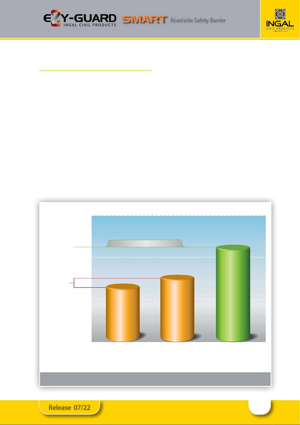
Wire Rope Barriers
Accepted within
Australia
100
156.4
2,000kg
pick-up truck
travelling at
100km/h and
25 degrees
8,000kg
truck travelling
at 80km/h and
15 degrees
2,270kg
pick-up truck
travelling at
100km/h and
25 degrees
137.8
132.3
125
150
175
NCHRP 350 TL4NCHRP 350 TL3MASHTL3
Note:The MASHTL4 impact severity is 209.3kJ
Figure 1: Comparison of Crash Test Impact Severities
Crash Test Performance Level
Impact
Severity
(kj)
Ezy-Guard Smart
4
Release 07/22
Roadside Safety Barrier
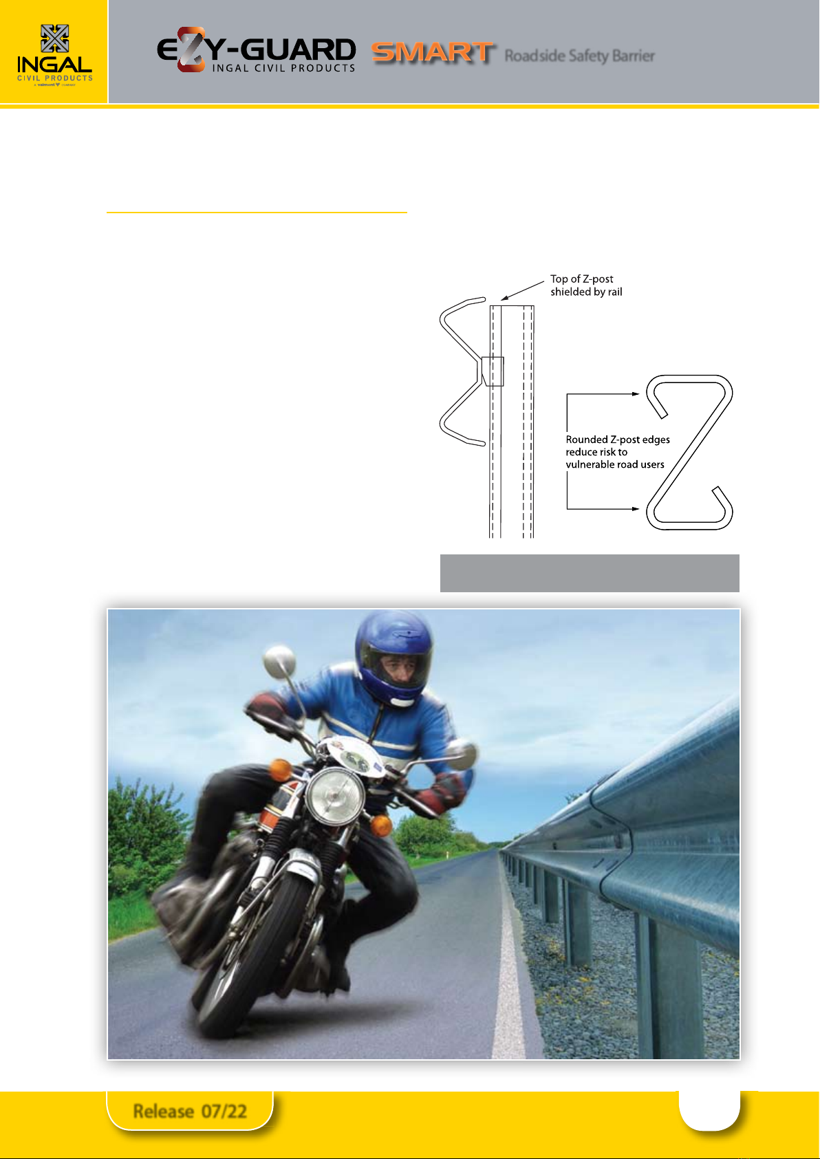
Figure 2: Ezy-Guard Smart Considerations for
Vulnerable Road Users
4.0 Consideration for Vulnerable
Road Users
Vulnerable road users include motorcyclists, pedestrians,
cyclists and other road users. Ezy-Guard Smart has been
designed to provide consideration to vulnerable road
users as follows:
Rounded Post Corners.
The Z-post contains smooth, rounded post edges and
corners mitigating the risk and severity of fractures and/
or contusions.
Energy Absorbing, Ductile Z-Posts.
Unlike traditional guardrailposts, the Z-posts are designed
to yield by bending near ground level. This bending
action absorbs impact energy reducing the potential for
post fracturing. A fractured or split guardrail post presents
a signicant laceration hazard to vulnerable road users.
The Ezy-Guard Smart design does not contain any elements
that become projectiles and there are no aggressive edges.
Shielded Posts.
The revolutionary design of Ezy-Guard Smart shields the
top of the supporting Z-posts by positioning the top of
the rail above the posts. This eliminates dangerous snag
points, reducing the potential for the barrier to dismount
motorcyclists or cyclists. This is a signicant safety benet
compared to all guardrail and cable barrier designs
currently used within Australia.
5
Release 07/22
Roadside Safety Barrier
1600mm
200mm
1800mm
385mm
G4 W Beam
1800mm
440mm
Type B Guardfence
Ground
surface
1600m
m
200m
m
1800m
m
385m
m
G4
W
Beam
W BeamW
1800m
m
440m
m
Ty
pe B Guard
fe
nc
e
Ground
su
rf
ac
rfacrf
e
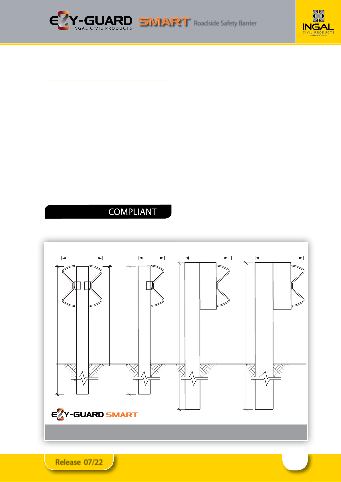
Figure 3: Ezy-Guard Smart Width Comparison
5.0 Features and Benets
5.1 Fully Compliant to MASH TL3
Ezy-Guard Smart, a member of the Ezy-Guard family, is
Australia’s only locally produced, fully compliant MASH
TL3 guardrail barrier system.
The MASH TL3 test condition (2,270kg pickup travelling
at 100km/h and 25 degrees) represents a 42% increase in
impact energy when compared to the current Australian
public domain guardrail systems using C-posts and
steel blocking pieces, which has only demonstrated
1600C containment (1,600kg passenger car travelling at
100km/h and 25 degrees).
The MASHTL3 test condition also represents a 13% to 18%
increase in energy when compared to the superseded
NCHRP 350 Test Level 3 or Test Level 4 impacts.
5.2 Rapid Installation & Repair
Ezy-Guard Smart installation can be up to twice as fast
to install than conventional guardrail barriers and unlike
cable barrier systems, no concrete is required.
The Ezy-Guard Smart design uses fewer components and
features 1,600mm Z-posts that are rapidly driven into the
ground. The Z-post embedment depth is just 880mm, a
reduction of 20% when compared to traditional guardrail
posts. This reduces installation time providing signicant
cost savings.
Since the Z-posts are designed to yield by bending near
ground level, damaged posts can be removed easily which
reduces the time spent by work crews on the roadside.
5.3 Narrow Width
With a system width of just 200mm, Ezy-Guard Smart
is up to 55% narrower than the current public domain
guardrail barrier systems. Ezy-Guard Smart conserves
valuable formation width and allows a greater recovery
width to be provided for errant vehicles.
MASH TL3
1600mm
200mm
1800mm
385mm
G4 W Beam
1800mm
440mm
Type B Guardfence
Ground
surface
Double sided W-Beam
730mm
310mm
1600mm

6
Release 07/22
Roadside Safety Barrier
5.4 Installation in Rock, Asphalt or Concrete
Mowing Strips
The design of the Z-post diers from traditional posts in
that it relies on the yielding of the post by bending near
ground level rather than the yielding of the surrounding
soil during a vehicle impact. This makes the Z-post suitable
for installation in rock, asphalt or concrete mowing strips.
A traditional guardrail post is designed to absorb some
crash energy through post rotation in the soil prior to post
failure. Restraining these traditional posts by setting them
in narrow holes drilled into solid rock, by setting them in
thick asphalt layers or concrete, or by placing a mowing
strip around the posts can lead to a failure of the system to
safely contain and redirect the errant vehicle.
5.5 Manual Handling
Ezy-Guard Smart uses fewer components than the public
domain guardrail systems. Z-posts weighing just 12.3kg
are 50% lighter than traditional C-posts. The lightweight
Z-post reduces manual lifting by installation crews.
The rounded edges of the Z-post provides a handlelike
grip when lifting, reducing the possibility of hand
lacerations. The Z-prole allows the installer to maintain
a rm grip and facilitates correct lifting techniques.
5.6 Locally Designed & Produced
Ezy-Guard Smart is manufactured in Australia by Ingal
Civil Products using steel manufactured by BlueScope
Steel. Z-posts and rail are stamped providing traceability
to material mechanical and chemical analysis certicates.
Hot dip galvanising is performed internally by Ingal and
daily inspections ensure zinc thickness readings are in
accordance with AS/NZS standards..
5.7 Soft Ride-Down Decelerations
The Ezy-Carriage controls the release of the w beam
rail from the Z-posts. This controlled release reduces
the potential for vehicle pocketing and provides a soft
ridedown for vehicle occupants.

7
Release 07/22
Roadside Safety Barrier
Figure 4: Vehicle Trajectory
6.0 Performance
Ezy-Guard Smart provides protection from roadside
hazards located close to the edge of the travelled way. The
sectional strength of the 4 Z-post reduces lateral deection
whilst providing controlled containment and redirection.
Crash testing guidelines provide a set of requirements
that is “worst practical conditions” in order to
demonstrate the barriers impact performance. When
the combined eects of vehicle mass, impact speed
and angle of impact are considered, the testing criteria
represents the extremes of impact conditions to be
expected in real-world situations.
6.1 Deection
The transverse deection of a barrier during a crash is
dependent upon many factors, including mass, speed,
and impact angle of the errant vehicle.
Since crash testing typically represents the extremes
of these parameters, a review of the proposed barrier
location can be undertaken to assess the following;
• Maximum attainable impact angle;
• Design speed; and
• Design vehicle.
Figure 4 illustrates the vehicle trajectory when turned
towards the barrier. The maximum attainable angle, Ø is
limited by the speed of the vehicle and the lateral oset,
x to the barrier.
The maximum attainable angle for various speeds and
osets is shown in Figure 6 and is derived using a point
mass model and assumes maximum steering and a
coecient of friction of 0.7 (dry pavement).
If the deection needs to be reduced due to the
proximity of a road side hazard, this can be achieved by
reducing the post spacing. Refer Table 2 for deections
with post spacing reduced to 1m. The reduced post
spacing should be initiated 10m upstream and returned
to standard spacing 10m downstream of the hazard.
6.2 Slopes
The maximum cross fall for an installation of Ezy-Guard is
10H:1V (10%).
6.3 Batter Hinge Proximity
Installations of safety barriers in close proximity to a
batter hinge point should be considered within the
requirements of the road controlling authority Extended
Design Domain.
Ezy-Guard Smart has been successfully crash tested to
MASH TL3 with posts installed on the rounding point
of a 2H:1V batter. The batter was comprised of AASHTO
M147-65 Standard Soil.
Suitability of the ground conditions and/or erosion of the
batter should be considered by the installation designer
prior to installation of a safety barrier near a batter slope.
It is recommended the barrier be installed with the
maximum oset to hinge point possible.
As the proximity of the batter slope may reduce the soil
support to the post, the designer should also consider
the use of an increased post embedment, refer section
7.5.2.
vehicle
barrier
x
vehicle path
v
e
hi
c
l
e
ba
rri
er
x
vehicle
p
at
h
7.5.2.
Figure 5: Ezy-Guard Smart on curves

8
Release 07/22
Roadside Safety Barrier
Ezy-Guard Smart with Ingal MPR - Motorcyclist Protection
Figure 6: Maximum Attainable Angle by Speed and Oset.
1m vehicle oset to barrier
2m vehicle oset to barrier
3m vehicle oset to barrier
4m vehicle oset to barrier
5m vehicle oset to barrier
6m vehicle oset to barrier
7m vehicle oset to barrier
8m vehicle oset to barrier
Impact Angle
(degrees)
Table 1. Ezy-Guard Smart Deections
Speed (km/h) Dynamic Deection (m)
Post Spacing Test Standard Dynamic Deection
70 2m MASH TL2 0.90
100 1m MASH TL3 1.05
100 2m MASH TL3 1.65
7050 60 80 90 100 110 120 130
0.0
5.0
10.0
15.0
20.0
25.0
30.0
35.0
40.0
7
0
50
6
0
80
90
100
11
0
1
20
130
0.0
5
.
0
10.
0
1
5.0
20.0
2
5.
0
30.0
3
5.
0
40
.
0
m
Example
Example
Speed (km/hr)
* If further reduction of the deection is required, please contact your local Ingal Civil Products representative.
9
Release 07/22
Roadside Safety Barrier
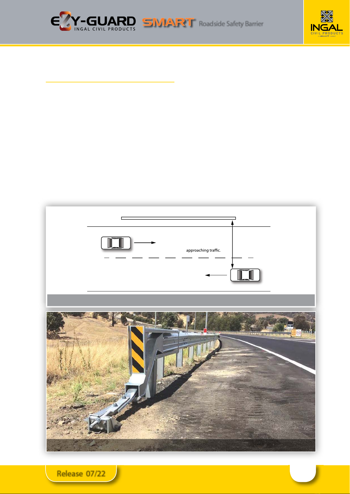
Figure 7: Clear Zone Requirement for the use of Departure Terminals
Figure 8: ET-SS End Terminal
7.0 Installation
7.1 Terminals
Guardrail end terminals are designed to provide a soft
gating impact preventing the end rail from spearing
an impacting vehicle. Terminals also introduce tensile
and exural strength necessary to ensure redirection
performance of the length-of-need section.
Ezy-Guard Smart is installed at a system height of
730mm,
measured to the top of the rail. This height is
compatible with the ET2000 Plus and public domain
terminals such as the MELT (NSW, Qld, SA)
.
Departure terminals should only be installed if they are
located outside the clear zone of approaching trac. See
Figure 7. The clear zone is the horizontal width of space
available for the safe use of an errant vehicle.
The clear zone is dependant upon the speed of the vehicle.
Guidelines are contained with regulatory publications.
Terminals should be installed in accordance with the
proprietor’s drawings and specications. Z-posts are
not to be used in the terminals unless approved by the
proprietor.
The installation of terminals will typically incorporate the
use of blocking pieces positioned between the posts
and rail. This will require the supporting posts to be
oset from the set-out line used for the installation of the
Z-posts which do not require blocking pieces.
In addition, the post spacing used in the terminals
and transitions may vary from the 2m spacing used
for installation of Ezy-Guard Smart. The required post
spacing for terminals and transitions will be contained in
the proprietor’s drawings.
approach terminal barrier departure terminal
A departure terminal can
only be used if located
outside the clear zone of
approac
h
termina
l
b
arrier
d
eparture termina
l
A
d
eparture termina
l
can
only be used if located
outs
i
de
t
h
e
c
l
ea
r z
o
n
e
o
f

10
Release 07/22
Roadside Safety Barrier
7.2 Minimum Length Requirements
There are two geometric methods used to determine
the likely trajectory of a vehicle that leaves the road
in the vicinity of a roadside hazard and the minimum
length of barrier required to protect from this hazard.
The most common method is the run-out length
method and an alternative is a method based on angle
of departure.
Prior to design or installation, designers should consult
the relevant road authority to establish the local
jurisdictional practice as the methods may result in
dierent lengths. Both methods are detailed in the
Austroads Guide to Road Design – Part 6.3.
For instances where geometric constraints limit the
installation of the recommended length under the
above design methods, the absolute minimum length
of minimum length of need for Ezy-Guard Smart is
dependent on the design containment level.
• For a Test Level 2 containment, where the design
vehicle is a 2,000kg pick-up, the minimum length of
Ezy-Guard Smart between terminals is 12m.
• ForaMASHTestLevel3containment,wherethedesign
vehicle is a 2,270kg pick-up, the minimum length of
Ezy-Guard Smart is 20m between terminals.
7.3 Sequence of Work
Where Ezy-Guard Smart is being constructed on a
road open to trac, it is recommended that the work
commence at the end closest to the approaching trac.
Leading terminals and transitions shall be commissioned
at the earliest practical time.
7.4 Modications
Ezy-Guard Smart shall be constructed in the
conguration as detailed in Ingal Civil Products’
drawings. This is the conguration in which the system
has been crash tested. No modications shall be made
to the system unless veried by Ingal Civil Products.
Flame cutting of rails or posts is not permitted. Saw
cutting and drilling is permitted in the event that a post
is to be installed at an irregular spacing and/or rock is
encountered and the post embedment depth has been
modied in accordance with Table 4.
Any modication carried out after fabrication will require
repair to the galvanized coating. A corrosion resistant
treatment shall be applied to the freshly cut surface, ICP
recommend a Zinc metal spray in accordance with ISO
2063 or AS/NZS 2312.
7.5 Soil Requirements & Embedment Depth
The Z-post is designed to yield by bending near ground
level during impact. Provided the post is embedded
in material that allows this failure mechanism to be
replicated, the Ezy-Guard Smart functionality will be
retained. The Z-posts will provide lateral resistance until
the impacting vehicle causes deformation of the posts.
At this point the Ezy-Carriages will provide a controlled
release of the rail from the Z-posts resulting in safe
vehicle containment and redirection.
7.5.1 Standard Soil
Ezy-Guard Smart has been evaluated for installation
in standard soil in accordance with AASHTO standard
specications for ‘Materials for Aggregate and Soil
Aggregate Subbase, Base and Surface Courses,’
designation M 147.
When installed in standard soil, the 880mm embedment
depth of the Z-post is sucient for installation up to
300mm from the rounding point on 2:1 embankment
slopes.
Installations within 300mm from the hinge point should
be considered within the requirements of Section 6.3
and the road controlling authority Extended Design
Domain requirements.
7.5.2 Weak Soil
Ezy-Guard Smart has been evaluated for installation
in weak soil in accordance with AASHTO standard
specication for ‘Fine Aggregate for Hydraulic Cement
Concrete,” designation M 6.
When installed in weak soil, the 880mm embedment
depth of the Z-post is sucient for installation up to
500mm of the rounding point on 2:1 embankment
slopes. If installation is required within 500mm of the
rounding point, the post embedment depth is required
to be increased to 1,050mm. A longer Z-post is available
from Ingal for these applications.
Installations within 300mm from the hinge point should
be considered within the requirements of Section 6.3
and the road controlling authority Extended Design
Domain requirements.
11
Release 07/22
Roadside Safety Barrier
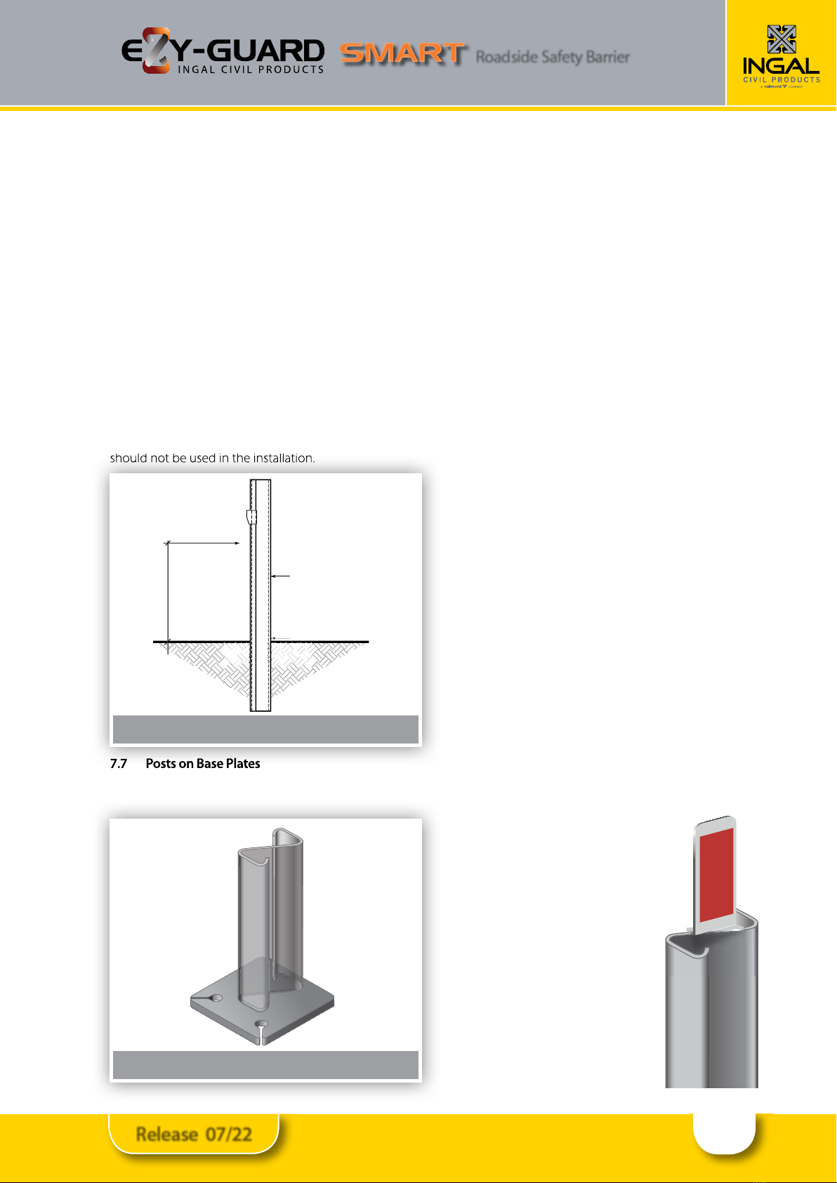
Figure 10: Z-Post on Base Plate
7.6 Post Pullover Test
In the event that the soil type cannot be veried, the
suitability of the post foundation can be established
through a post pullover test.
This is undertaken by applying a 1kN load to the post,
550mm above ground level. The load is applied prior to
the attachment of the rail. Displacement at the base of
the post shall not exceed 1mm whilst the load is applied.
An alternative post pull over test can be achieved via a
more destructive means, whereby a load of 1.2 tonnes is
applied to the test post at a height of 700mm.This loading
approximates the probable capacity of the post and
should be able to be maintained with minimal rotation
of the post in the soil. At the completion of the testing
the post should be removed from the test location and
should not be used in the installation.
7.7 Posts on Base Plates
In the event that the Z-post cannot be installed to
the required in-ground depth, the use of a base plate
mounted on a suitable foundation can be adopted. Posts
on base plates are typically used at culvert locations, and
in areas where underground services restrict posts from
being driven into the ground. Refer to Ingal Civil Products
drawings for the installation of posts on base plates.
7.8 Z-Posts in Rock
Traditional guardrail posts are designed to yield in the
surrounding soil and their placement in rock or concrete
is problematic. Restraining the traditional posts by setting
them in narrow holes drilled into rock, setting them in
concrete or placing a mowing strip around the posts
can lead to a failure of the system to safely contain and
redirect the errant vehicle.
The specially engineered Z-post dissipates energy by
yielding through bending near ground level. This means
that typical recommendations for the installation of a
traditional guardrail post in rock are not applicable to
the Z-post. When rock is encountered, the installation
guidelines as detailed in Table 4 are applied. If required
the bottom of the post may be cut onsite by a disc
grinder or equivalent steel cutting tool. A corrosion
resistant treatment will need to be applied to the freshly
cut surface, ICP recommend a Zinc metal spray in
accordance with ISO 2063 or AS/NZS 2312.
7.9 Non-Standard Post Spacing
Occasionally, a roadside hazard may prevent a post from
being installed at the recommended spacing. In these
instances it may be possible to stien the barrier with
reduced post spacing on the approach and trailing side
of the hazard, we would recommend you discuss these
options with your local Ingal Civil Products representative.
7.10 Delineation
A specially designed delineator is attached to the Z-post.
Typically,delineation isarranged sothat driversapproaching
from either direction will see only;
•Red retro-reectors on their left;
•White retro-reectors on their right
on two-way carriageways; and
•Yellow retro-reectors on their
right on one-way carriageways
and medians separating trac in
opposing directions
The spacing of delineators is
dependantupon driver lineofsight.As
a general rule delineators are provided
for installation every 20m on straight
alignments. Installation on curves will
require a closer spacing dependant
upon the radius of the roadway.
should not be used in the installation.
7.7
Posts on Base Plates
Figure 9: Z-Post Pullover Test
1kN Force
700mm
Embedded Z-Post
Ground Level
Displacement
less than 1mm
1
kN F
o
r
ce
550
mm
E
m
bedded
Z-P
ost
G
round Leve
l
Disp
l
acemen
t
l
ess
t
h
a
n 1mm

12
Release 07/22
Roadside Safety Barrier
Table 4: Installation of Ezy-Guard Smart Z-Posts in Rock
Site Condition Installation Requirements
Rock is
encountered at
the surface.
Drill a 110-300mm diameter
hole to a depth of 450mm,
install the post in the hole
and backll.
Rock is
encountered
within 450mm
of the surface.
Drill a 110-300mm diameter
hole 450mm into the rock
or to a minimum total post
embedment depth of
650mm, whichever comes
rst, install the post and
backll.
450
650 min.
0-450
rock
soil
450
rock

13
Release 07/22
Roadside Safety Barrier
Site Condition Installation Requirements
Rock is
encountered
450mm to
600mm below
ground.
Drill a 110-300mm diameter
hole 200mm into the rock
or to a minimum total post
embedment depth of
650mm, whichever comes
rst, install the post and
backll.
Rock is
encountered
600mm to
800mm below
ground.
Drill a 110-300mm diameter
hole 50mm into the rock
or to a minimum total post
embedment depth of
800mm, whichever comes
rst, and install the post and
backll.
200
650 min.
450-600
rock
soil
50
800 min.
600 – 800
rock
soil
14
Release 07/22
Roadside Safety Barrier
Figure 11:
Figure 12:
Figure 12:
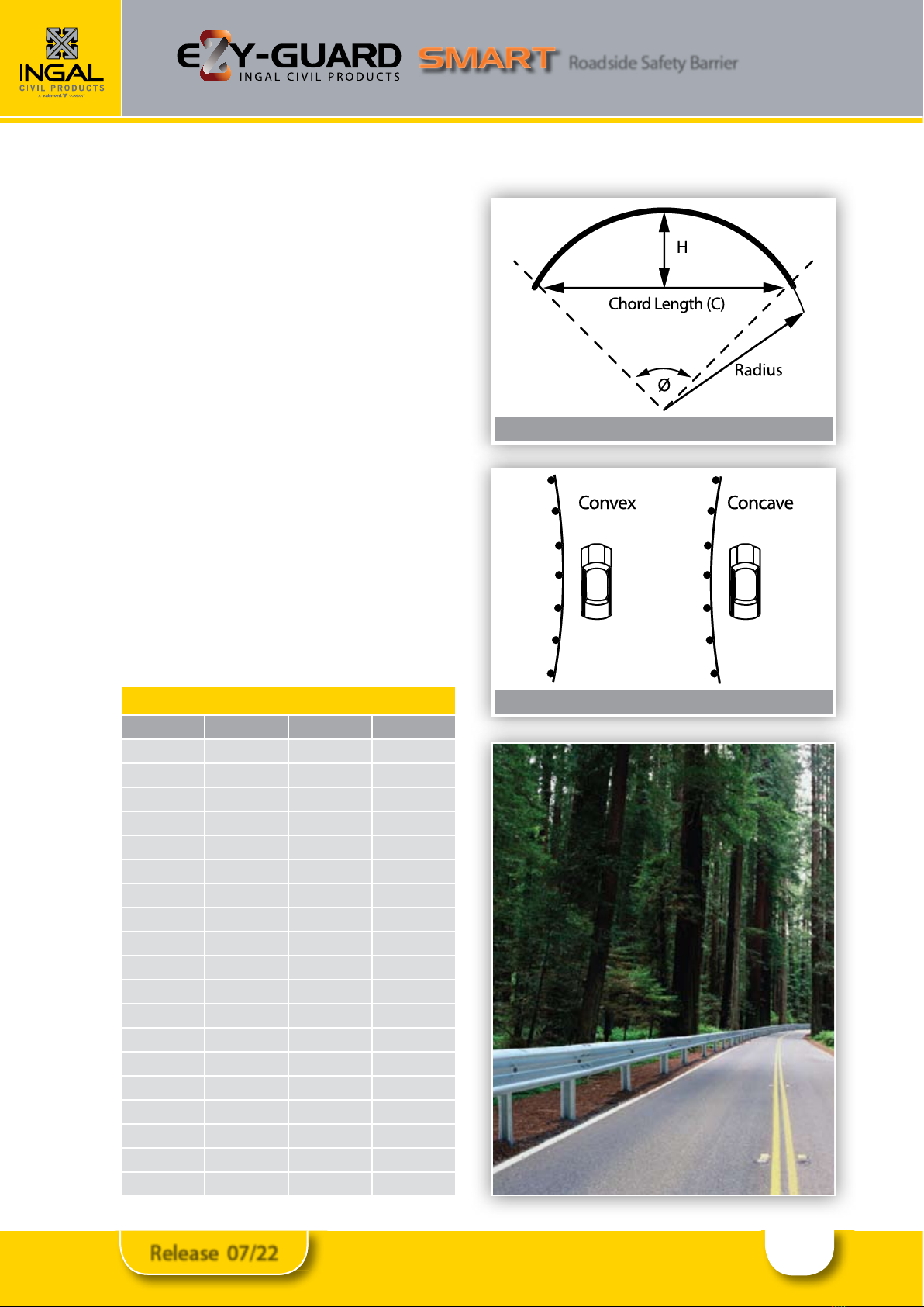
Figure 11: Curvature Measurements
Figure 12: Curvature Orientation
Table 5: Rail Curvature Values
Radius (m) Ø Degrees C (mm) H (mm)
2.4 95 3553 786
3 76 3710 642
4 57 3835 490
5 45 3894 395
6 28 3926 330
7 33 3946 284
8 29 3958 249
9 26 3967 221
10 23 3973 199
12 19 3982 166
14 16 3986 143
16 15 3990 125
20 12 3993 100
24 10 3995 83
28 8 3997 71
32 7 3997 62
35 73998 57
40 5 3998 50
45 5 3999 44
7.11 Curving of Rails
Guardrail used for the assembly of Ezy-Guard Smart
may be shop curved to t any radius from 2.4m to 45m
Convex. Curves in excess of 45m do not require shop
curving as the rail can be eld installed to suit. Guardrail
may be curved either concave or convex to the trac
face and can be part-curved along its length to suit site
requirements.
7.11.1 Measuring Curvature
1. Mark along the arc of the curve at 4m intervals.
2. Measure the corresponding chord length (C) - refer
to Figure 11.
3. Measure the corresponding centre oset (H) - refer
to Figure 11.
4. Use the values for C & H to select the radius from
Table 5.
5. Determine the curvature orientation from Figure 12.
7.11.2 Identication of Curved Rails
Where a rail has been factory curved by Ingal, the radius
of curvature is marked on the rear face of the rail.

15
Release 07/22
Roadside Safety Barrier
7.12 Installation Sequence
The following written instructions should be read in
conjunction with Ingal Civil Products’drawings.
A generic Safe Work Method Statement is available
from Ingal Civil Products to assist in the safe installation
of Ezy-Guard Smart. Suitable trac control should be in
place before any works.
Only items purchased from Ingal Civil Products shall be
used for the construction of Ezy-Guard Smart.
1. Ensure the area has been inspected for
underground hazards and where a service clash
has been identied, the barrier should be adjusted
longitudinally if possible.
2. Post locations are marked ensuring any xed object
hazard is located outside the expected dynamic
deection of the barrier
3. The post in relation to the direction of trac as per
orientated as per Figure 13.
4. Posts are spaced every 2m and are driven directly
into the ground and should be vertical. The post
installation process shall not cause damage to the
post, such that it reduces the eective operation
of the safety barrier or its design life, or introduces
sharp tearing edges, nor shall it cause damage to
pavement. If the Ezy-Carriage cannot freely move as
it is attached to the post as a result of deformation
of the post during installation, then the post shall
be replaced. The use of a vibrating post hammer
will reduce deformation to the top of the post and
install the post at a controlled rate.
5. Alternate to driving the posts, a minimum 110-
300mm hole can be augured and the post placed
in the hole. The posthole is then backlled with the
material that was excavated. If installing in soil, the
material should be placed in layers of 150mm and
suitably compacted to not less than the density of
the surrounding layers
6. The height of the Z-post above ground level is
720mm.
7. The Ezy-Carriage is attached to the face of the post.
The Ezy-Carriage will come to rest on the positioning
lug fabricated on the Z-post.
lug fabricated on the Z-post.
orientated as per Figure 13.
4.
Posts are spaced every 2m and are driven directly
Figure 13: Z-Post Orientation
FACING TRAFFIC
F
A
C
ING TRAFFI
C
Figure 14: Ezy-Carriage Orientation
Figure 15: Attachment of Carriage to Z-Post

16
Release 07/22
Roadside Safety Barrier
8. Rails are attached to the Ezy-Carriage using the
M16x30mm post bolts.The post bolts are identied
by the socket recess located in the head of the
bolt. The bolts are tightened to snug tight using a
10mm hex. key.
9. Rails are spliced together at every second post
using M16x32mm mushroom head bolts and
oversized nuts. There are 8 bolts required per splice
connection. A pinch bar may be used to assist in
the alignment of splice holes. The use of a driving
pin to elongate the slots is NOT to be used since
this may cause tearing of the rail at the slot location.
The bolts are tightened to snug tight.
10. Rails are orientated so that no leading edge is
presented to the trac face as shown in Figure 18.
11. It is recommended that posts be installed only a
few metres ahead of rail assembly to ensure correct
post spacing and alignment. On curves, the rails
can be used as a template and laid on the ground
to determine post locations.
12. Where possible, the barrier should form a smooth
line vertically and horizontally when viewed along
the line of the system, free from humps, sags or
other irregularities.
13. The Ezy-Guard Smart components are to be free
from splits, burrs or sharp edges after installation.
Any minor damage is to be repaired by applying
two coats of an organic zinc rich paint.
14. Any disturbed pavement or material around a
post shall be left dense, tight, and smooth so that
resistance to water penetration is similar to that of
the adjacent surface.
7.13 Back to Back W-Beam Installation
The Ezy-Guard Smart system can also be used in median
applications where the W-Beam is installed on both sides
of the post. This conguration requires a special post with
resistance tabs on both sides of the post. The installation
procedure is the same as for a single sided installation with
steps 8 thru 15 repeated on the opposite side of the post.
Refer drawing Ezy-SM-035 for further assembly detail.
7.14 Installation Tolerances
• The tolerance on height of the barrier shall be
+25mm/-0mm.
• The tolerance for the line of the barrier shall be plus or
minus 20mm in plan view.
• The tolerance for departure from the upright axis shall
be plus or minus 15mm at the top of the barrier.
• The tolerance on post spacing shall be plus or minus
25mm.
8.0 Maintenance
8.1 Preventative Maintenance
It is recommended that annual inspections be performed
to ensure the following;
• The system is appropriately delineated;
• Debris has not accumulated around the system that
may impede the performance of the barrier or the
trajectory of an impacting vehicle;
• The system is suitably anchored with appropriate
terminals and/or transitions. If the system is anchored
with terminals, the cable assembly shall be taut and
tensioned to its recommended value; and
• All splice bolts and post bolts are snug tight.
10mm hex. key.
Rails are spliced together at every second post
Figure 16: Post Bolt
The bolts are tightened to snug tight.
10.
Rails are orientated so that no leading edge is
Figure 17: Splice Bolt & Nut
presented to the trac face as shown in Figure 18.
Figure 18: Orientation of Rail Lap
TRAFFIC
DIRECTION
TRAFFI
C
DIRE
C
TI
O
N

17
Release 07/22
Roadside Safety Barrier
8.2 Ezy-Lift for Maintenance Overlays
For existing Ezy-Guard installations where the road
surface has been overlayed or resurfaced, resulting
in the barrier height being outside of the installation
tolerance, the Ezy-Lift carriage is available to bring the
W-Beam back to the appropriate height. The carriage
gives the option to lift the W-Beam by +50, +100, +150
and +180mm. Refer assembly drawing EZY-SM-137 for
further detail.
Installation sequence:
1. Unbolt M16x32 Splice Bolts at splice joint at either
end of W-Beam rail.
2. Unbolt each carriage bolt on W-Beam rail. Exercise
caution on removal of carriage bolts as rail will be
unsupported after removal and may fall to the ground.
3. Lay W-Beam on ground adjacent to original position.
4. Remove carriage from post and replace with Ezy-
Lift Carriage.
5. Reinstall carriage bolt and M16 washer into lowest
hole in carriage and tighten to snug tight using a
10mm hex key. Refer to Detail A on drawing.
6. Repeat steps 1 through 5 until required W-Beam rail
has been disassembled.
7. Determine the required lift by measuring the
height of overlay. The nominal W-Beam height of
Ezy-Guard Smart is 730mm.
8. Rails are to be re-attached to the Ezy-Lift carriage
using a M16x30mm post bolts and 75x45mm
rectangular washer at each post.
9. Rails are overlapped so that no leading edge is
presented to the trac face as shown in Figure 18.
10. Rails are spliced together at every second post using
M16x32mm splice bolts and oversized nuts. There
are 8 bolts required per splice connection. A pinch
bar may be used to assist in the alignment of splice
holes. The use of a driving pin to elongate the slots
is NOT to be used since this may cause tearing of
the rail at the slot location. The bolts are tightened
to snug tight.
9.0 Product Storage
All posts and rails are hot dip galvanized in accordance
with AS/NZS 4680. It is important that stored galvanized
work is stacked so that each item is well ventilated and
can adequately drain rainwater from its surfaces.
Poor storage can give rise to wet storage stain (white
rust) which is caused by water (rain or condensation) in
badly drained or ventilated conditions. This can occur
very quickly, particularly in warm, humid conditions.

18
Release 07/22
Roadside Safety Barrier
Figure 19: Ezy-Guard Smart Installation Tolerances
± 20mm lateral tolerance
from design position of rail
± 25mm post spacing
tolerance measured
at top of post
rail
rail
Plan View Side View
± 15mm
Front View
± 15mm
± 2
0
mm l
ate
r
a
l
to
l
e
r
a
n
ce
from desi
g
n position of rai
l
±
25mm post spacing
tole
r
a
n
ce
m
easu
r
ed
at to
p
of
p
os
t
r
a
il
rai
l
P
l
an Vie
w
S
i
de
Vi
ew
Height +25mm/–0mm
±
1
5
mm
Fr
o
n
t
Vi
ew
±
15mm
19
Release 07/22
Roadside Safety Barrier
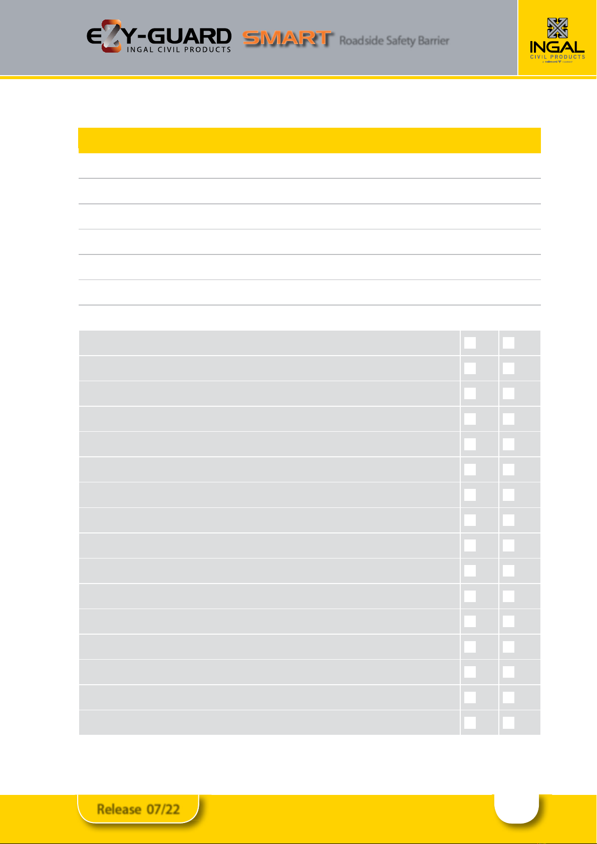
Ezy-Guard Smart Installation Checklist
Ezy-Guard Smart Installation Checklist
Customer:
Project:
Barrier ID:
Barrier Length:
Checked By:
Signed:
Date
Have the Z-posts been positioned every 2m Yes No
Have the Z-posts been correctly orientated in relation to the direction of trac Yes No
Is the construction of Ezy-Guard Smart within the allowable tolerances as detailed in Section 7.14 Yes No
Have the Ezy-Carriages been correctly orientated Yes No
Have the rails been attached to the Ezy-Carriages using the post bolts with the socket recess Yes No
Have the rails been spliced observing the correct lap Yes No
Have the rails been spliced with M16x32mm mushroom head bolts Yes No
Are all splice bolts and post bolts snug tight Yes No
Is Ezy-Guard Smart appropriately delineated Yes No
Is Ezy-Guard Smart suitably anchored with approved terminals Yes No
Are the cables in the terminals tensioned to their nominated torque Yes No
Has any minor damage been repaired using two coats of an organic zinc rich paint Yes No
Is the barrier system free from humps, sags or other irregularities Yes No
Has the ground or pavement around the post been left dense, tight and smooth Yes No
Are the barrier components free from splits, burrs or sharp edges after installation Yes No
Has the top of the post been cut or otherwise altered? Yes No
20
Release 07/22
Roadside Safety Barrier
Table 6: Damage Assessment of Ezy-Guard Smart
Type of Defect Description of the Defect Action to be Taken
Galvanizing damage on
Z-Posts.
The sum total of the damaged area does not exceed 35cm2(0.5% of the total
surface area).
The sum total of the damaged area exceeds 35cm2
An organic zinc rich epoxy paint is to be applied to the repair area
in two coats.
The Z-post is to be replaced.
Galvanizing damage
on rails.
The sum total of the damaged area does not exceed 200cm2(0.5% of the
total surface area) and no individual damaged area does not exceed 40cm2.
The sum total of the damaged area exceeds 200cm2(0.5% of the total
surface area) and/or an individual damaged area exceeds 40cm2.
An organic zinc rich epoxy paint is to be applied to the repair area
in two coats.
The rail is to be replaced.
Mechanical damage on
Ezy-Carriages.
The Ezy-Carriage has chips or cracks. The Ezy-Carriage is to be replaced.
Mechanical damage on
Z-Posts.
The post is bent.
The Ezy-Carriage cannot travel freely along the post due to distortion.
The post is to be replaced.
The post is to be replaced.
Mechanical damage
on rail.
The rail is dented, twisted or flattened.
There are tears in any part of the rail.
The slots in the rail are distorted.
The rail is to be replaced.
The rail is to be replaced.
The rail is to be replaced.
Mechanical damage
on bolts.
The body of the bolt is distorted.
The thread of the bolt is damaged.
The bolt is to be replaced.
The bolt is to be replaced.
Disturbance of material
around posts
The material around the post is loose or uncompacted. Any disturbed pavement or material around a post shall be left
dense, tight and smooth so that resistance to water penetration is
similar to that of the adjacent surface.
10.0 Repair
10.1 Bush Fire Damage
Ezy-Guard Smart does not contain any plastic, timber or
rubber components that will burn.
The performance of galvanised coatings when subjected
to res depends upon a number of factors, such as ame
duration, intensity and the characteristics of the galvanised
coating.
Typical bushre conditions may expose steel structures to
an air temperature of 800°C for periods of up to 120 seconds,
however zinc coatings are generally reective and will not
absorb heat at the same rate as an uncoated steel surface.
Depending on the section thickness of the steel, the actual
steel surface temperature may not exceed 350°C.
Typically, the bushre ame duration and intensity are not
high enough to compromise the structural strength of
the steel. The hot dip galvanized coating will also typically
remain unaected through a bushre event. If the bushre
causes damage to the galvanized surface, then the item(s)
shall be replaced.
10.2 Damage Assessment
In the event of a vehicle impact, damage to the barrier is
to be assessed in accordance with Table 6.
A Safe Work Method Statement is available from Ingal
Civil Products upon request to assist in the safe repair of
Ezy-Guard Smart.
Any item that is replaced is to be reinstated observing
the installation tolerances nominated in Section 7.13.
Only items purchased from Ingal Civil Products shall be
used for the repair of Ezy-Guard Smart.
10.3 Dismantling Sequence
Prior to undertaking dismantling due to a vehicle impact,
the area should be assessed for hazards. These include
trip hazards, sharp edges and snag points.
During a vehicle impact, the rail will disengage from
the posts as they yield by bending at ground level. The
recommended dismantling sequence is as follows;
1. Dismantle the railsplice by removing the M16x32mm
mushroom head bolts and nuts. There are 8 bolts
located at each splice location.
2. Rails that are still attached to posts outside the
impact area are disconnected by removing the
M16x30mm post bolts. A 10mm hex key is required.
3. Once the area is clear of damaged rail, the posts can
be removed. Since the posts yield by bending near
ground level, a sling or chain can be attached below
the bent section.
4. The damaged post can be lifted using a backhoe or
post extractor attachment.
5. Any disturbed pavement material shall be left
dense, tight, and smooth prior to the installation of
replacement posts.
Table of contents
Other INGAL Safety Equipment manuals


Popular Safety Equipment manuals by other brands

3M
3M DFS 700 Installation and user manual

Brüel & Kjaer Vibro
Brüel & Kjaer Vibro VC-8000 Short-form instruction / Safety instruction

Innotech
Innotech VERT-SET-50 Safety instructions and instruction manual

CHARLY
CHARLY DIAMONDcross 100 Basic Operating instructions manual

Petzl
Petzl SEQUOIA quick start guide

B-Safety
B-Safety ClassicLine PROTECTO Operation manual


