Trinity Highway MATT User manual

PN 628155
Created February 2022
™
®
TRINITY
HIGHWAY
Ahead of e Cur®

TrinityHighway.com 1 Part Number: 628155
©2021 Trinity Highway Products, LLC
February 2022
MATT™
MEDIAN ATTENUATING TREND® TERMINAL
The Median Attenuating TREND® Terminal (“MATT™”) has been tested to the American Association of State
and Highway Transportation Officials (“AASHTO”) Manual for Assessing Safety Hardware, 2nd Edition (2016), with 2020
Errata (“MASH”) criteria, as a Test Level 3 (“TL-3”) device.
Product Description
Assembly Manual
15601 Dallas Parkway
Suite 525
Addison, Texas 75001
WARNING: The local highway agency, distributors, owners, and contractors are
RESPONSIBLE for the assembly, maintenance, and repair of the MATT™. Failure to
fulfill these RESPONSIBILITIES with respect to the assembly, maintenance, and repair
of the MATT™ could result in serious injury or death.
IMPORTANT: These instructions are for standard assembly specified by the appropriate
highway agency. In the event the specified system assembly, maintenance, or repair would
require a deviation from standard assembly parameters, contact a Trinity Highway Products,
LLC (“Trinity Highway”) representative. This system has been submitted for Federal-aid
reimbursement eligibility to the Federal Highway Administration (“FHWA”) for use on the
National Highway System (“NHS”) under strict criteria utilized by that agency.
This manual must be available to the worker overseeing and/or assembling the product at all times. For
additional copies, contact Trinity Highway at (888) 356-2363 or visit TrinityHighway.com/Products.
The instructions, illustrations, and specifications are based on the latest MATT™ information available to Trinity
Highway at publication. We reserve the right to make changes at any time. Please visit
TrinityHighway.com/product-category/end terminals to confirm the latest revision.
TrinityHighway.com
February 2022
MATT™
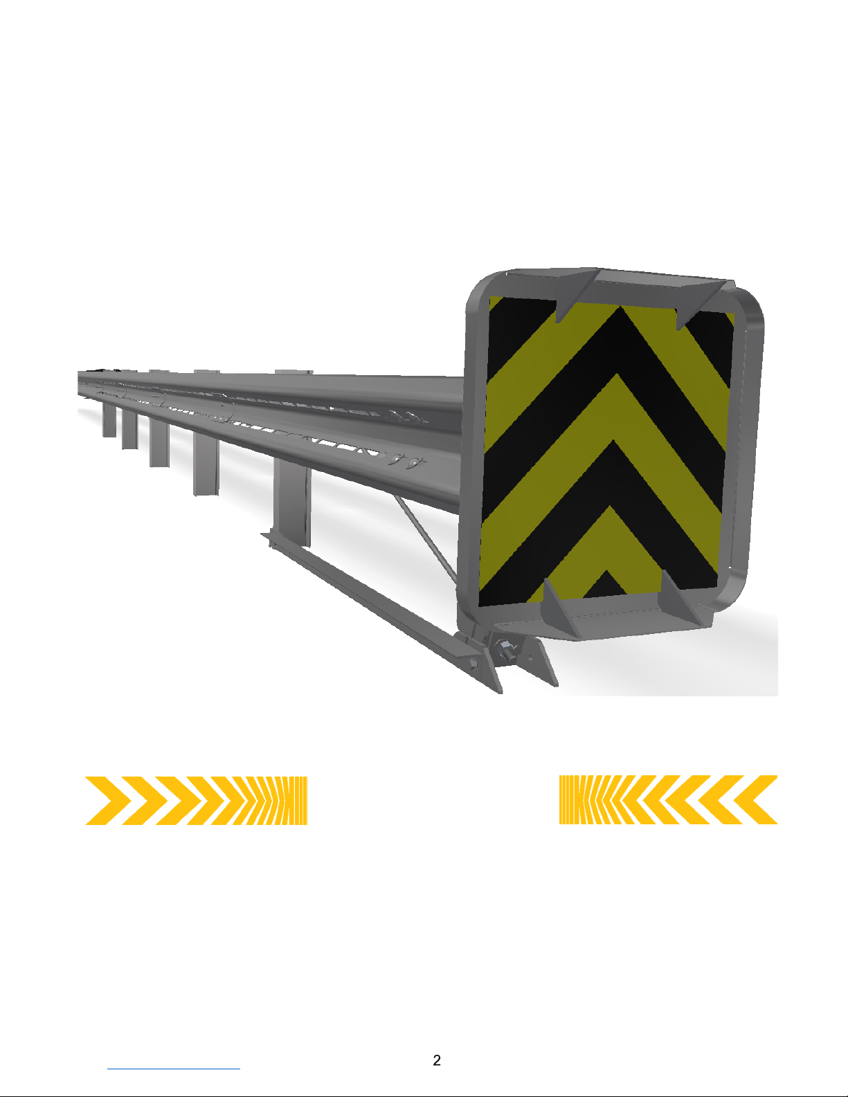
The MATT™ is a tangent, double-sided, re-directive/gating and energy absorbing attenuator/end terminal,
for use with various longitudinal highway barriers, in either unidirectional or bidirectional traffic
applications, to include roadside, shoulder, median and gore installations.

TrinityHighway.com
February 2022
Table of Contents
MATT™ ACRONYMS and ABBREVIATIONS .......................................................................................................... 4
Customer Service Contacts ....................................................................................................................................... 4
Limitations and Warnings ......................................................................................................................................... 5
Overview ................................................................................................................................................................... 6
Recommended Tools ................................................................................................................................................ 7
Site Preparation ......................................................................................................................................................... 8
Post Placement ........................................................................................................................................................ 9
Rigid Pavement and Rock ..................................................................................................................................... 9
Inspect Shipment .................................................................................................................................................. 9
MATT™ System Components/Hardware ............................................................................................................. 11
Assembly Steps …… .............................................................................................................................................. 15
STEP 1: MATT™ Post Layout (Posts 1-6) .................................................................................................. 16
STEP 2A: MATT™ CR Post 1 Bottom With Soil Plate Assembly .................................................................. 17
STEP 2B: MATT™ SYTP® With Soil Plate Assembly Post 2 ........................................................................ 18
STEP 2C: MATT™ SYTP® With Soil Plate W-Shaped Assembly for Post 3 to 5 ........................................... 19
STEP 2D: MATT™ Line Post With Soil Plate W-Shaped Assembly for Post 6 .............................................. 20
STEP 3: MATT™ Angle Strut Assembly ...................................................................................................... 21
STEP 4: MATT™ CR Post 1 Top Assembly ................................................................................................ 22
STEP 5A: MATT™ Double Spacer Assembly Posts 1 and 2 ......................................................................... 23
STEP 5B: MATT™ Single Spacer Assembly Posts 3 to 5 ............................................................................. 24
STEP 6: MATT™ 12 Gauge Transition Guardrail With Fin-4, 9’-4 1/2” [2.858 m] ..................................... 25
STEP 7: MATT™ 12 Gauge, Slotted Intermediate Guardrail With Fin-3, 6’-3” [1.905 m] Posts 4-5 ............ 26
STEP 8: MATT™ 12 Gauge, Slotted Intermediate Guardrail With Fin-3, 6’-3” [1.905 m] Posts 3-4 ............ 27
STEP 9: MATT™ 12 Gauge, Slotted Intermediate Guardrail-2, 6’-3” [1.905 m] .......................................... 28
STEP 10: MATT™ 10 Gauge, Slotted Front Guardrail-1, 6’-3” [1.905 m] ...................................................... 29
STEP 11: MATT™ Cable Assembly ............................................................................................................. 30
STEP 12: MATT™ 10 Gauge Head Rail Assembly, 1’- 9 3/4” [552 mm] ....................................................... 31
STEP 13: MATT™ Delineation Assembly ...................................................................................................... 32
STEP 14: MATT™ Head Tube Assembly ...................................................................................................... 33
STEP 15: MATT™ Impact Head Assembly ................................................................................................... 34
STEP 16: MATT™ Nuts To Be Torqued and Cable Tensioning .................................................................... 35
MATT™ System Assembly/Repair Checklist (File with Project/Maintenance Records) ......................................... 36
MATT™ System Routine Inspection Checklist (File with Maintenance Records) .................................................. 37
APPENDIX A: AASHTO Roadside Design Guide Roadside (Shoulder) Grading Detail ........................................ 38
APPENDIX B: AASHTO Roadside Design Guide Median Grading Detail ............................................................. 39

TrinityHighway.com
February 2022
MATT™ ACRONYMS and ABBREVIATIONS
AASHTO American Association of State Highway and Transportation Officials
CFR Code of Federal Regulation
CR Cable Release (Ref: CRP®)
FHWA Federal Highway Administration
Nm Newton-Meters
MASH Manual for Assessing Safety Hardware 2ND Edition (2016), Errata in 2020
MATT™ Median Attenuating TREND® Terminal
MGS Midwest Guardrail System
MUTCD Manual on Uniform Traffic Control Devices
NCHRP National Cooperative Highway Research Program
NHS National Highway System
OSHA Occupational Safety & Health Administration
PPE Personal Protective Equipment
SYTP® Steel Yielding Terminal Post®
TL-3 Test Level-3
Trinity Highway Trinity Highway Products, LLC
Customer Service Contacts
Trinity Highway is committed to the highest level of customer service. Feedback regarding the
MATT™, its assembly procedures, supporting documentation, and performance is always
welcome. Additional information can be obtained from the contact information below:
Trinity Highway
Telephone
(888) 356-2363 (USA)
+1 214 589 8140 (International)
Contact Link
TrinityHighway.com/Contact
Website:
www.trinityhighway.com
Trinity Highway Products, LLC
15601 Dallas Parkway
Suite 525
Addison, TX 75001

TrinityHighway.com
February 2022
Limitations and Warnings
Trinity Highway, in compliance with MASH,
contracts with ISO 17025 A2LA accredited testing
laboratories to perform crash tests, evaluate tests,
and submit the test results to the FHWA for review.
MATT™ was tested to MASH-2nd Edition (2016), with
2020 Errata TL-3 criteria and may be used in Test Level
1, Test Level 2, and Test Level 3 applications – when
installed at the full Test Level 3 system length of 34’ 4-
1/2” [10.477 m]. These tests typically evaluate product
performance defined by MASH involving a range of
vehicles on roadways, approximately 1,100kg [2,420
lb.] and full size pickup trucks (approximately 2,270
kg [5,000 lb.] at 100 kph [62 mph].
The MATT™ is tested pursuant to the test matrix
criteria of MASH as designated by AASHTO and
FHWA. The FHWA/AASHTO tests are not
intended to represent the performance of
systems when impacted by every vehicle type or
in every impact condition existing on the
roadway. Every departure from the roadway is a
unique event.
Trinity Highway expressly disclaims any warranty or
liability for injury or damage to persons or property
resulting from any impact, collision or harmful
contact with its products, other vehicles, or nearby
hazards or objects by any vehicle, object or person,
whether or not the products were assembled in
consultation with Trinity Highway or by third parties.
The MATT™ is intended to be assembled, delineated,
and maintained within the state/specifying agency and
federal guidelines. It is important for the
state/specifying agency to select the most appropriate
product configuration for site specifications.
The state/specifying agency’s careful evaluation of the
site layout, vehicle population type and speed, traffic
direction, and visibility are some of the elements that
require evaluation in the selection of a highway product.
For example, curbs could cause an untested effect
on an impacting vehicle.
After an impact with the system, all debris must be
removed from the area immediately in compliance with
the most applicable state/specifying agency policy. The
specified MATT™ must be evaluated and restored to
its original specified condition or replaced as the
state/specifying agency determines/requires, as soon
as possible. Product selection, approval, proper
installation, and maintenance of any highway product is
the sole responsibility of the state/specifying agency.
WARNING: Under NO circumstances shall the rail
within the MATT™ be curved/radiused, between
Post 1 and Post 6.
All metric dimensions are “soft conversions” and
as such should be considered as reference only.
Safety Alert Symbols appear throughout this
manual and indicate Danger, Warning, Caution or
Important statements. Failure to read and follow
these warnings could result in serious injury or
death in the event of a vehicle impact with the
system.
WARNING: Do not assemble, maintain, or repair
the MATT™ until you have read this manual
thoroughly and completely understand it. Ensure
that all Danger, Warning, Caution, and
Important
statements within the manual are completely
followed. Please call Trinity Highway at (888)
356-2363 if you have any questions about
instructions in this manual.
WARNING: Safety measures incorporating
appropriate traffic control devices and personal
protective equipment ("PPE") specified by the
state/specifying agency must be used to protect
all personnel while at the assembly,
maintenance, or repair site. Work gloves, apron,
eye protection,
safety-toe
shoes,
and
back
protection shall be used.
WARNING: Ensure the assembly site meets all
appropriate Manual on Uniform Traffic Control
Devices (“MUTCD”) and the state/specifying
agency standards.
WARNING: Use only Trinity Highway parts that are
specified by Trinity Highway for use with the
MATT™ for assembling, maintaining, or repairing
the MATT™. Do not utilize or otherwise
commingle parts from other systems even if those
systems are other Trinity Highway Products or
Systems. Such configurations have not been
tested, nor have they been approved for use.
Assembly,
maintenance or repairs using
unspecified parts or accessories is strictly
prohibited. Failure to follow this warning could
result in serious injury or death in the event of
a vehicle impact with such an UNACCEPTED
system.
WARNING: Do NOT modify the MATT™ in any
way.
IMPORTANT: Trinity Highway makes no
recommendation whether use or reuse of any part
of the MATT™ is appropriate or acceptable after
system impact. It is the responsibility of the
state/specifying agency and its engineers to make
that determination.
IMPORTANT: It is the responsibility of owner,
state/specifying agency, or specifier to inspect the
MATT™ after assembly is complete to ensure the
instructions provided in this manual have been
strictly followed.
TrinityHighway.com
February 2022
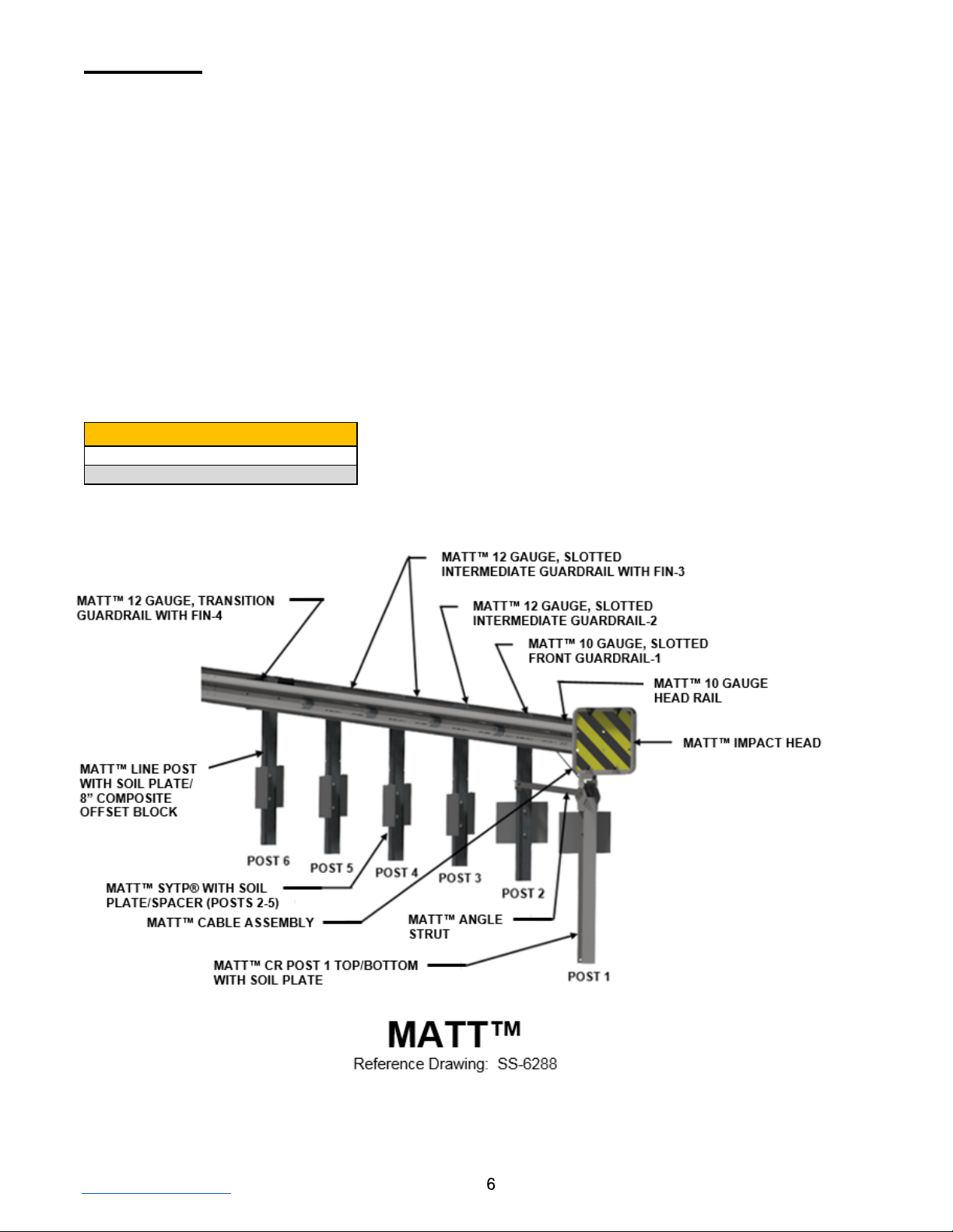
Overview
The MATT™ has a system length of 34’-4 1/2” [10.477 m] long and is a tangent, 31” [787mm] (+1” -0”) [+25 mm, -0 mm]
high, double-sided, re-directive/gating and energy absorbing attenuator/end terminal available for use with various
longitudinal highway barriers, in either unidirectional or bidirectional traffic applications.
The MATT™ consists of MATT™ 10 and 12 gauge slotted guardrail, MATT™ 12 gauge transition guardrail with an
integrated fin and MATT™ 12 gauge slotted guardrail with an integrated fin, MATT™ 10 gauge head rail, MATT™
impact head, MATT™ CR top and bottom posts, MATT™ SYTP® with soil plate, MATT™ system line post with soil
plate, MATT™ angle strut, MATT™ cable assembly, MATT™ spacers, composite offset blocks and various other
required hardware accessories.
When connecting the MATT™ to Median MGS using offset blocks other than 8” [200 mm] – such as Median MGS
utilizing 12” [300 mm] offset blocks – refer to the AASHTO Roadside Design Guide (current edition) for appropriate
minimum taper/flare rates for barrier design.
When connecting the MATT™ to W-beam guardrail heights other than 31” [787 mm], or rigid or semi-rigid barriers, (i.e.
concrete barrier, thrie beam, wall or bridge pier) a transition will be required - see FHWA and/or state/specifying agency
standards.
Gauge Conversions
10 Gauge [3.43 mm]
12 Gauge [2.67 mm]

TrinityHighway.com
February 2022
Recommended Tools
Documentation
•
Manufacturer’s MATT™ Product Description Assembly Manual (Current Version).
•
MATT™ Drawing(s) SS-6288 (Current Version).
Personal Protective Equipment
•
Eye Protection
•
Work Gloves
•
Safety-Toe Shoes
•
Back Protection
•
Hard Hat
•
Reflective Vest
•
Apron
Miscellaneous
•
Traffic Control Equipment and Plan per state/specifying agency standards and the MUTCD.
•
SAE Combination Wrench Set
•
Socket Set & Socket Wrench
•
Hammer
•
Chalk Line
•
Tape Measure
•
Marking Paint and Pen
•
Straight Edge
•
Level
•
Plumb Line
•
Post Pounder (commonly used for driving posts)
•
Auger
•
Soil Tamper
•
5/8” Alignment Tool (Drift Pin), used to help align panels
•
Locking Pliers and/or Pipe Wrench
•
Calibrated Torque Wrench, capable of measuring 65 ft.-lbs. [88 Nm].
Note: The provided list of tools is a general recommendation and should not be considered an
extensive list. Depending on specific site conditions and the complexity of the assembly, the required
tools may vary. Decisions as to what tools are needed to perform the job are entirely the responsibility
of the state/specifying agency and the selected contractor performing the assembly of the system at
the state/specifying agency’s site.

TrinityHighway.com
February 2022
Site Preparation
The MATT™ has a system length of 34’-4 1/2” [10.477 m], long and is a tangent, 31” [787mm] (+1” -0”) [+25 mm, -0 mm]
high, double-sided, re-directive/gating and energy absorbing attenuator/end terminal available for use with various
longitudinal highway barriers, in either unidirectional or bidirectional traffic applications.
It may be specified for use by the state/specifying agency in conjunction with strong post W-beam guardrail systems on
the NHS or other roadway. The decision to specify the MATT™ for a particular project is the responsibility of the
state/specifying agency design engineer who must ensure that the most appropriate end treatment has been selected
for the specific site conditions.
The MATT™ is designed to be attached directly to double sided strong post W-beam guardrail systems that have been
accepted under MASH or NCHRP Report 350 crash test criteria that utilize 8” [200 mm] offset blocks.
IMPORTANT: The MATT™ must not be attached directly to a weak post W-beam
guardrail system without an approved weak-post-to-strong-post transition plus a
minimum of 12’-6” [3.810 m] strong post W-beam guardrail with 6’-3” [1.905 m] post
spacing. The 12’-6” [3.810 m] strong post W-beam guardrail must be placed between
the MATT™ and the weak-post- to-strong-post transition.
IMPORTANT: Under NO circumstances shall the rail within the MATT™ be curved,
between Post 1 and Post 6. Ensure all MATT™ post spacings are 6’-3” [1.905 m] on
center.
IMPORTANT: When used with rigid barriers, (i.e. concrete barrier, wall or bridge pier) a
semi to rigid barrier transition will be required (see state/specifying agency standards).
IMPORTANT: Ensure the state/specifying agency standard transition is used when
connecting the MATT™ to a system other than double sided, 31” [787 mm] high MGS with 8”
[200 mm] offset blocks.
IMPORTANT: Ensure that the MATT™ application conforms to the AASHTO Roadside
Design Guide, current edition to include appropriate grading details.
IMPORTANT: Trinity Highway does not direct grading. Proper site grading must be
accomplished before assembly of the MATT™ in accordance with local guidelines OR
the AASHTO Roadside Design Guide (see Appendix A and B), whichever is more
stringent. Failure to follow this warning could result in serious injury or death in the
event of a vehicle impact with the system.
IMPORTANT: The Beginning Length of Need (“BLON”) for the MATT™ was established
during MASH Test 3-35 at Post 3, which is 12’-6” [3.810 m] from Post 1.
IMPORTANT: Only 8” [200 mm] composite offset blocks can be used at Post 6 and only
the supplied special MATT™ spacers/double spacers at all other post locations.
MATT was tested to MASH-2nd Edition (2016), with 2020 Errata Test Level 3 criteria and
may be used in Test Level 1, Test Level 2, and Test Level 3 applications – when installed
at the full Test Level 3 system length of 34’ 4-1/2” [10.477 m].

TrinityHighway.com
February 2022
Post Placement
The MATT™ posts are inserted into the soil using an auger or post pounding equipment for placement.
If an auger is used, ensure diameter is large enough to allow for proper compaction of state/specifying
agency approved fill material. All MATT™ posts must be assembled within established standard
construction tolerances, including being plumb. Compaction for all posts must be within the
state/specifying agency guidelines.
Danger: It is the responsibility of the installer to ensure all above & below ground utilities
as well as drainage structures are located, marked, and identified prior to using an auger
or post pounding tool in accordance with state/ specifying agency guidelines. Failure to
follow this warning could result in serious injury or death.
Rigid Pavement and Rock
If rigid pavement (e.g. concrete or asphalt) of any thickness is encountered within the system, ensure a
proper “leave-out” area (the specified size of open space as defined in the AASHTO Roadside Design
Guide) and/or per the state/specifying agency is provided around the posts and filled with the state/
specifying agency approved backfill material.
If solid rock is encountered at post locations 3-6, refer to the state/specifying agency guidelines and/or
the AASHTO Roadside Design Guide for requirements for embedment depth into the rock and size of
the hole. If solid rock is encountered at post locations 1-2, auger a hole in the rock large enough for full
post embedment and proper compaction of approved fill material.
Drilling Holes into rock
Caution: It is the responsibility of the installer to consult Occupational Safety & Health
Administration (“OSHA”) silica respiratory standard 29 Code of Federal Regulation (“CFR”)
1910.134 for debris removal and ensure compliance.
Inspect Shipment
Carefully unpack and inspect all components for damage. Check the received parts against the packing
list supplied with the system. If any parts are damaged, missing, or unspecified; do not attempt to assemble
the system and contact Trinity Highway immediately (p. 4).
Warning: Use only Trinity Highway parts that are specified by Trinity Highway for
use with the MATT™ for assembling, maintaining, or repairing the MATT™. Do not
utilize or otherwise commingle parts from other systems even if those systems
are other Trinity Highway Products or Systems.

TrinityHighway.com
February 2022
ID
MATT™ COMPONENTS/HARDWARE (506288B)
PN
QUANITY
A
MATT™ Impact Head
628342B
1
B
MATT™ 12 Gauge Transition Guardrail With Fin-4, 9’-4 1/2” [2.858 m]
628289A
2
C
MATT™ 12 Gauge, Slotted Intermediate Guardrail With Fin-3, 6’-3” [1.905 m]
628337A
4
D
MATT™ 12 Gauge, Slotted Intermediate Guardrail-2, 6’-3” [1.905 m]
628274G
2
E
MATT™ 10 Gauge, Slotted Front Guardrail-1, 6’-3”[1.905 m]
628347G
2
F
MATT™ 10 Gauge Head Rail, 1’- 9 3/4” [552 mm]
628339A
2
G
MATT™ Single Spacer
628281A
6
H
MATT™ Double Spacer
628280A
2
I
MATT™ Head Tube
628275A
1
J
MATT™ Backing Plate
628338G
8
K
MATT™ CR Post 1 Top
628285A
1
L
MATT™ CR Post 1 Bottom – used with soil plate
628276A
1
M
MATT™ SYTP® 6’-0” [1.829 m] – used with soil plate
628271G
4
N
MATT™ System Line Post 6’-0” [1.829 m] – used with soil plate
628270G
1
O
MATT™ Angle Strut
628279G
1
P
MATT™ Cable Assembly 3/4” x 7’-5” [19 mm x 2.260 m]
119506G
1
Q
Cable Anchor Bracket Angle
33909G
1
R
MATT™ Strut Adapter Plate
628348G
1
S
5/16” x 1.75” Hex Bolt [8 mm x 44 mm]
4211G
2
T
5/8” x 1.75” Hex Bolt Grade 5 (A325) [16 mm x 44 mm]
3391G
6
U
5/8” x 1.25” GR Bolt [16 mm x 31 mm]
3360G
16
V
5/8” x 2” Hex Bolt A307 [16 mm x 51 mm]
3403G
6
W*
5/8” x 2” GR Bolt Grade 5 (A325) [16 mm x 51 mm]
118614G
62
Y
5/16” Hex Nut [8 mm]
3245G
2
Z*
5/8” Heavy Hex Nut A563 [16 mm]
3361G
66
AA
5/8” Round Washer [16 mm]
4372G
8
BB
5/8” GR Hex Nut [16 mm]
3340G
36
CC
1” Flat Washer [25 mm]
4902G
10
DD
1” Hex Nut [25 mm]
3910G
2
EE
5/8” Flat Washer (1/4” Thick) [16 mm] [6 mm thick]
118615G
62
FF
1/2” x 1.5” Hex Bolt [13 mm x 38 mm]
113457G
4
GG
1/2” Flat Washer [13 mm]
118009G
8
HH
1/2” Hex Nut [13 mm]
115939G
4
JJ
5/16” Flat Washer
3240G
2
KK
8” [200 mm] Composite Offset Block (wood is not allowed)
Various
2
MM
MATT™ Soil PL, 1/4” x 18” x 24” [6 mm x 457 mm x 610 mm] for Posts 1-2
628273G
2
NN
MATT™ Soil Plate W-Shaped (Multi-Directional) for Posts 3-6
628269G
4
OO
5/8” x 3.50” Hex Bolt Grade 5 (A325) [16 mm x 90 mm]
113660G
10
TT
5/8” x 10” GR Bolt A307 [16 mm x 254 mm]
3500G
2
Optional Delineation Available From Trinity Highway
YY
25” x 25” [625 mm x 625 mm] Yellow/Black Reflector (Median/Roadside)
105379B
1
ZZ
25” x 25” [625 mm x 625 mm] Yellow/Black Reflector (Gore)
105380B
1
Gauge Conversions
10 Gauge [3.43 mm]
12 Gauge [2.67 mm]
* Fastener combinations at 62 locations of “W”, 5/8” x 2” GR Bolt Grade 5 (A325) and
“Z”, 5/8” Heavy Hex Nut A563 DH require the Nuts to be torqued to 65 ft-lb [88
Newton-Meters “Nm”], (+/- 3 ft-lb) [+/- 4 Nm]. See Step 16 for the 62 locations.
TrinityHighway.com
February 2022
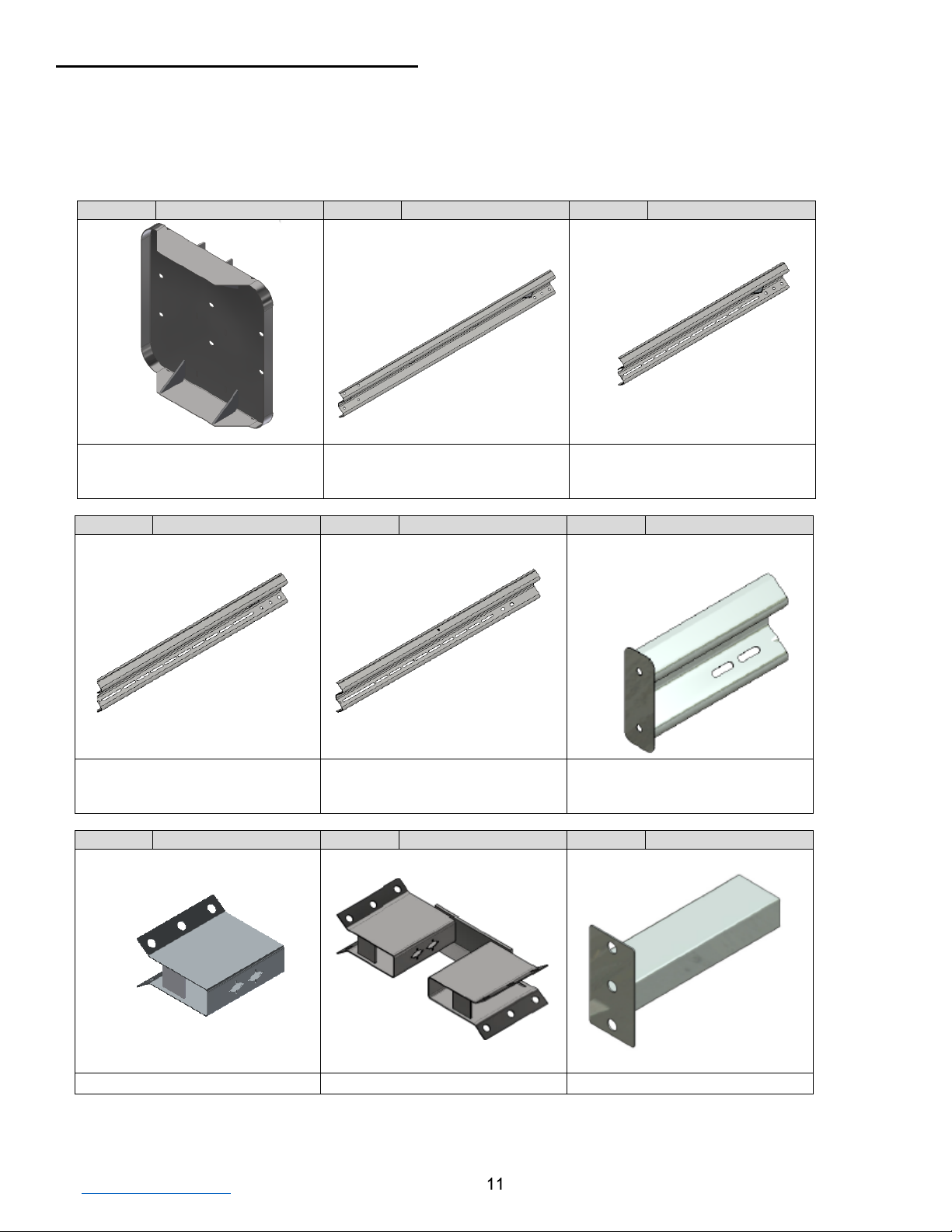
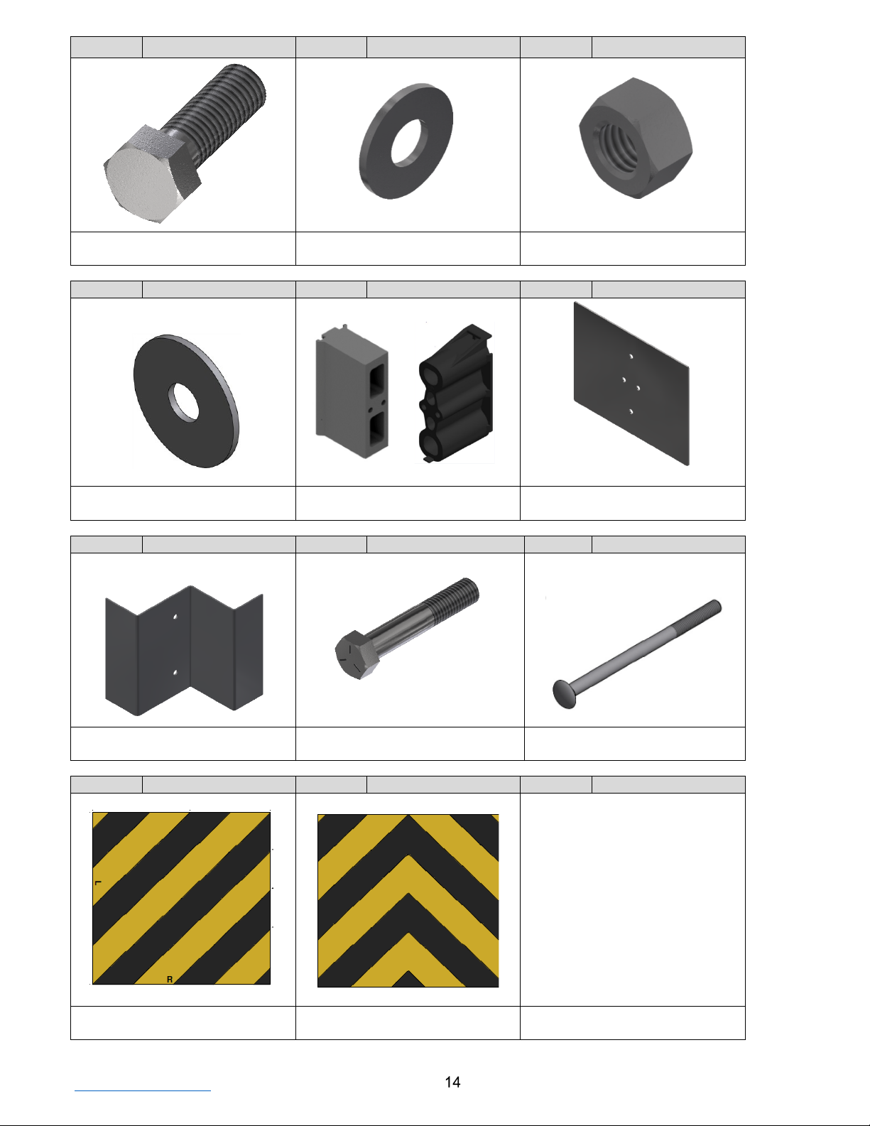
MATT™ Components/Hardware
Below is a pictorial depiction of the components/hardware for MATT™. Please see the Trinity Highway drawings
and page 10 of this manual for specific lists of components/hardware and quantities required for MATT™
selected to be assembled.
Note: The following components/hardware are not shown to scale.
ID: A
PN: 628342B
ID: B
PN: 628289A
ID: C
PN:628337A
MATT™ Impact Head
MATT™ 12 Gauge, Transition,
Guardrail With Fin-4,
9’-4 1/2"
MATT™ 12 Gauge, Slotted
Intermediate Guardrail With Fin-3,
6’-3”
ID: D
PN: 628274G
ID: E
PN: 628347G
ID: F
PN : 628339A
MATT™ 12 Gauge, Slotted
Intermediate Guardrail-2,
6’-3”
MATT™ 10 Gauge, Slotted Front,
Guardrail-1,
6’-3”
MATT™ 10 Gauge,
Head Rail,
1’-9 3/4”
ID: G
PN: 628281A
ID: H
PN: 628280A
ID: I
PN: 628275A
MATT™ Single Spacer
MATT™ Double Spacer
MATT™ Head Tube

TrinityHighway.com
February 2022
ID: J
PN: 628338G
ID: K
PN: 628285A
ID: L
PN: 628276A
MATT™ Backing Plate
MATT™ CR Post 1 Top
MATT™ CR Post 1 Bottom
ID: M
PN: 628271G
ID: N
PN:628270G
ID: O
PN: 628279G
MATT™ SYTP® 6’-0”
MATT™ Line Post 6’-0”
MATT™ Angle Strut
ID: P
PN:119506G
ID: Q
PN: 33909G
ID: R
PN: 628348G
MATT™ Cable Assembly
3/4” x 7’-5”
Cable Anchor Bracket Angle
MATT™ Strut Adapter Plate
SYTP® Holes
TrinityHighway.com
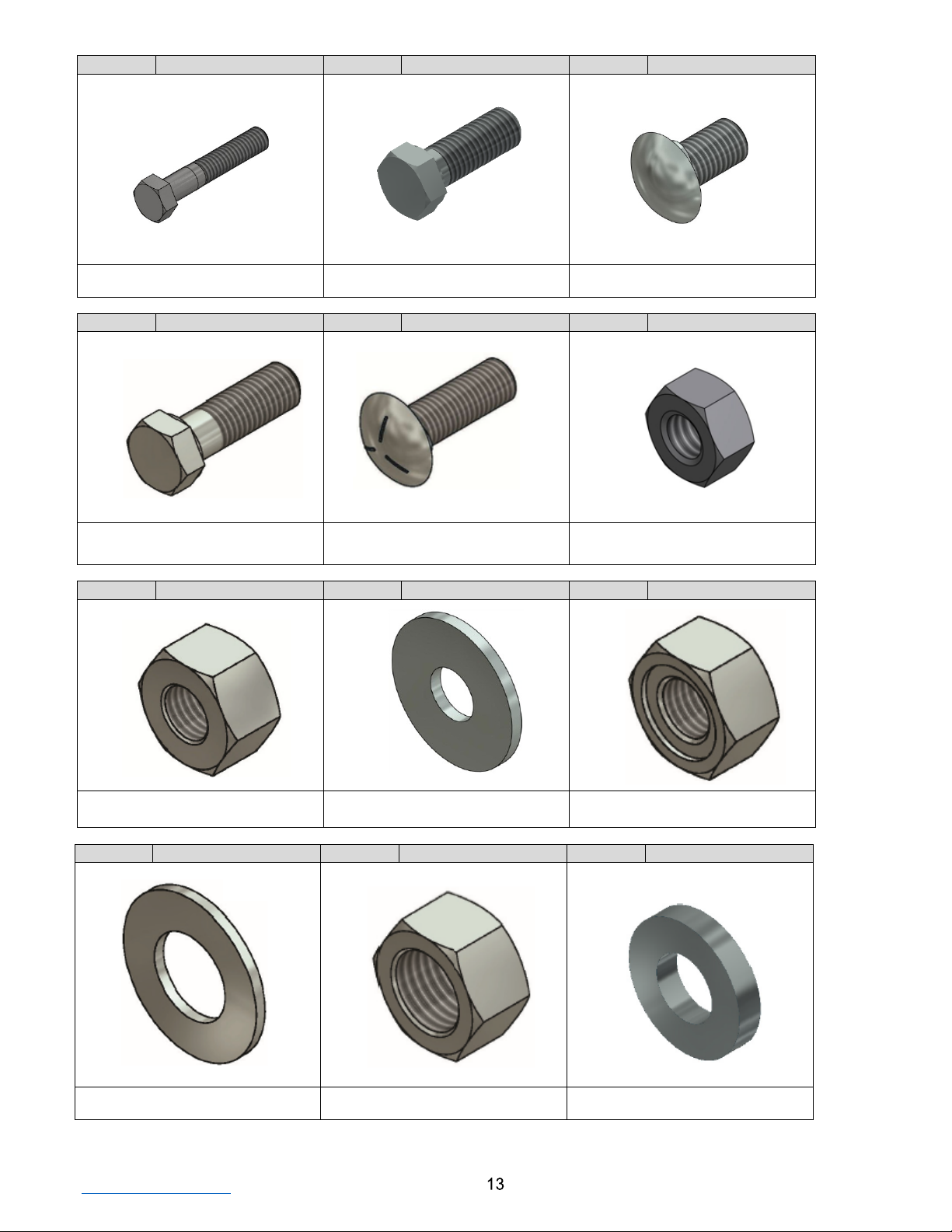
February 2022
ID: S
PN: 4211G
ID: T
PN: 3391G
ID: U
PN: 3360G
5/16” x 1.75” Hex Bolt
[8 mm x 44 mm]
5/8” x 1.75” Hex Bolt (A325)
[16 mm x 44 mm]
5/8” x 1.25” GR Bolt
[16 mm x 31 mm]
ID: V
PN: 3403G
ID: W
PN: 118614G
ID: Y
PN: 3245G
5/8” x 2” Hex Bolt A307
[16 mm x 51 mm]
5/8” x 2” GR Bolt (Grade 5)
[16 mm x 51 mm]
5/16” Hex Nut
[8 mm]
ID: Z
PN: 3361G
ID: AA
PN: 4372G
ID: BB
PN: 3340G
5/8” Heavy Hex Nut A563 DH
[16 mm]
5/8” Round Washer
[16 mm]
5/8” GR Hex Nut
[16 mm]
ID: CC
PN: 4902G
ID:DD
PN: 3910G
ID: EE
PN: 118615G
1” Flat Washer
[ 25 mm]
1” Hex Nut
[ 25 mm]
5/8” Flat Washer [1/4” Thick]
[16 mm] [6 mm thick]
TrinityHighway.com
February 2022
ID: FF
PN: 113457G
ID: GG
PN: 118009G
ID: HH
PN: 115939G
1/2” x 1.5” Hex Bolt
[13 mm x 38 mm]
1/2” Flat Washer
[13 mm]
1/2” Hex Nut
[13 mm]
ID: JJ
PN: 3240G
ID: KK
PN: Various
ID: MM
PN: 628273G
5/16" Flat Washer
[8 mm]
8” [200 mm] Composite
Offset Block
MATT™ Soil Plate Posts 1 & 2
ID: NN
PN: 628269G
ID: OO
PN: 113660G
ID: TT
PN: 3500G
MATT™ Soil Plate W-Shaped
Posts 3-6
5/8” x 3.50” Hex Bolt Grade 5
(A325) [16 mm x 90 mm]
5/8” x 10” GR Bolt A307
[16 mm x 254 mm]
ID: YY
PN: 105379B
ID: ZZ
PN: 105380B
ID:
25” x 25” [625 mm x 625 mm]
Yellow/Black Reflector (Right/Left)
25” x 25” [625 mm x 625 mm]
Yellow/Black Reflector (Gore)
TrinityHighway.com
February 2022
Assembly Steps
To ensure an accurate assembly of the MATT™ Terminal, it is recommended that steps be
completed in order. ALL STEPS MUST BE COMPLETED.
Below ground portions in some assembly steps are not shown for clarity.
See Step 16 for bolt/nuts combinations that must be torqued to 65 ft-lb [88 Nm] (+/- 3 ft-lb)
[+/- 4 Nm].
After the system is fully assembled, for Steps 5A and 5B, tighten the double/single
spacers to a snug position with a minimum of two (2) bolt threads protruding beyond the
nut for all hardware that was assembled loosely, ensuring bolt is seated for these steps.
MATT™ 10 Gauge, Slotted Front Guardrail WithOUT Fin-1, 6’-3” [1.905 m] PN 628347G
MATT™ 12 Gauge, Slotted Intermediate Guardrail WithOUT Fin-2, 6’-3” [1.905 m] PN 628274G
MATT™ 12 Gauge, Slotted Intermediate Guardrail WITH Fin-3, 6’-3” [1.905 m] PN 628337A
MATT™ 12 Gauge, Transition Guardrail WITH Fin-4, 9’-4 1/2” [2.858 m] PN 628289A
B
C
D
E
TrinityHighway.com
February 2022
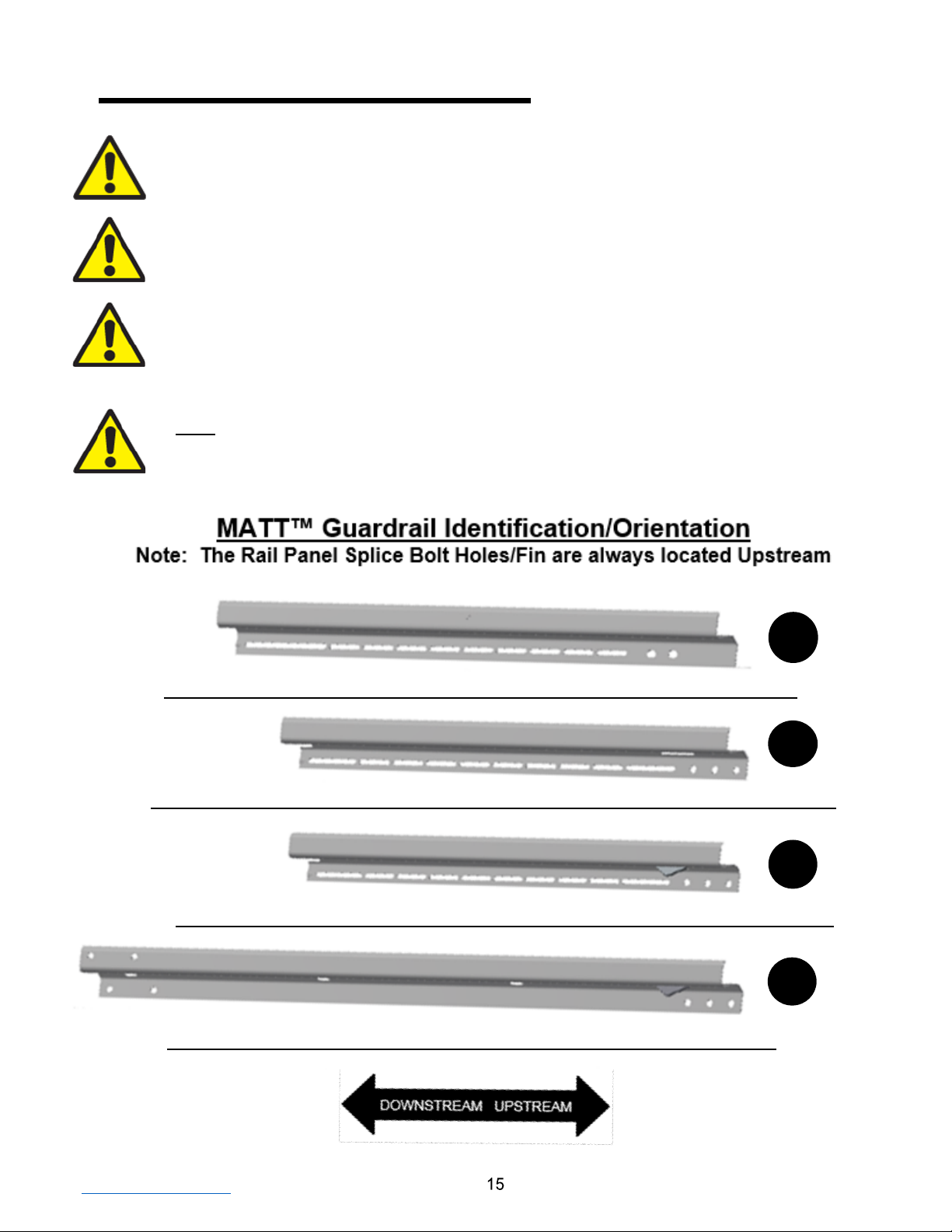
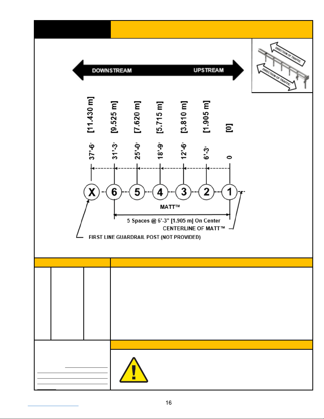
STEP 1
MATT™ Post Layout (Posts 1-6)
PARTS
INSTRUCTIONS
Reference: SS-6288
1. Layout the post locations as shown above.
2. Layout and placement of the posts are critical to the assembly of the
MATT™.
3. All MATT™ posts are spaced at 6’-3” [1.905 m] on center and installed
reasonably plumb.
4. MATT™ Posts 2-6 heights are 32” [813 mm] (+1”, -0”) [+25 mm, -0 mm] above
finished grade.
5. The height of the MATT™ CR Post 1 Bottom is 4” [100 mm] (+1”, -0”) [+25mm,
-0 mm] above finished grade.
Use only Trinity Highway parts
that are specified herein for the
MATT™ for assembling,
maintaining, or repairing the
MATT™. Do not utilize or
otherwise commingle parts from
other systems even if those
systems are Trinity Highway
systems.
WARNINGS
Ensure proper site grading in accordance with the state/specifying
agency guidelines and/or the AASHTO Roadside Design Guide,
whichever is more stringent.
Failure to follow this warning could result in serious injury or death in
the event of a vehicle impact with the system.

TrinityHighway.com
February 2022
STEP 2A
MATT™ CR Post 1 Bottom With Soil Plate
Assembly
PARTS
INSTRUCTIONS
L
628276A
1 EA
Reference: SS-6288
1. Assemble the MATT™ Soil Plate (Part MM) to the downstream side of the
6’-0” [1.829 m] MATT™ CR Post 1 Bottom (Part L) as shown above using
specified hardware (Parts T, BB).
2. Tighten all threaded hardware to a snug position with a minimum of two (2)
bolt threads protruding beyond the nut.
3. Assemble the 6’-0” [1.829 m] MATT™ CR Post 1 Bottom With Soil Plate as
shown above at location established in Step 1.
4. Ensure that the MATT™ Strut Hole is assembled on the upstream side of
the post.
5. Ensure the top of the MATT™ CR Post 1 Bottom With Soil Plate is 4” [100
mm] (+1”, -0”) [+25 mm, -0 mm] above finished grade.
T
3391G
2 EA
BB
3340G
2 EA
MM
628273G
1 EA
Use only Trinity Highway parts that
are specified herein for the MATT™
for assembling, maintaining, or
repairing the MATT™. Do not
utilize or otherwise commingle
parts from other systems even if
those systems are Trinity Highway
systems.
WARNINGS
Ensure the MATT™ Soil Plate is on the downstream side of the
CR Post 1 Bottom and Strut Hole is upstream.
Ensure threaded hardware is tightened to a snug position with a
minimum of two (2) bolt threads protruding beyond the nut.
Ensure the top of the MATT™ CR Post 1 Bottom With Soil Plate is
4” [100 mm] (+1”, -0”) [+25 mm, -0 mm] above finished grade.
Failure to follow these warnings could result in serious injury or
death in the event of a vehicle impact with the system.
POST 1
TrinityHighway.com
February 2022
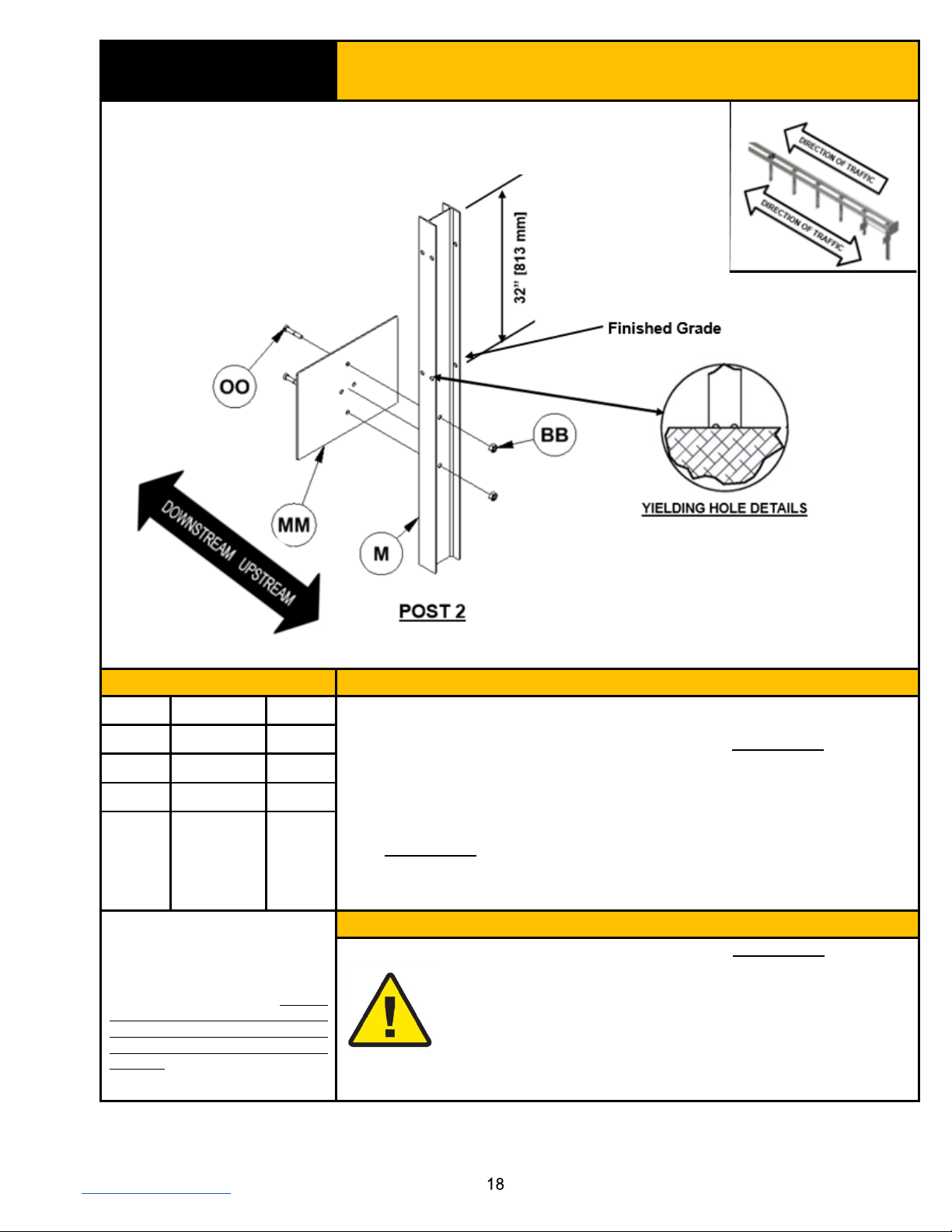
STEP 2B
MATT™ SYTP® With Soil Plate Assembly
Post 2
PARTS
INSTRUCTIONS
M
628271G
1 EA
Reference: SS-6288
1. Assemble the MATT™ Soil Plate (Part MM) to the downstream side of the
6’-0” [1.829 m] MATT™ SYTP® (Part M) as shown above using specified
hardware (Parts BB, OO).
2. Tighten all threaded hardware to a snug position with a minimum of two (2)
bolt threads protruding beyond the nut.
3. Assemble the 6’-0” [1.829 m] MATT™ SYTP® with Soil Plate on the
downstream side of the post as shown above for Post 2 at location
established in Step 1.
4. Ensure the center of the SYTP® Holes are approximately at finished grade
(+1”, -0”) [+25 mm, -0 mm].
BB
3340G
2 EA
MM
628273G
1 EA
OO
113660G
2 EA
Use only Trinity Highway parts that
are specified herein for the MATT™
for assembling, maintaining, or
repairing the MATT™. Do not
utilize or otherwise commingle
parts from other systems even if
those systems are Trinity Highway
systems.
WARNINGS
Ensure the MATT™ Soil Plate is on the downstream side of the
MATT™ SYTP®.
Ensure the center of the SYTP® Holes are approximately at finished
grade (+1”, -0”) [+25 mm, -0 mm].
Ensure the Post spacing is as established in Step 1.
Ensure threaded hardware is tightened to a snug position with a
minimum of two (2) bolt threads protruding beyond the nut.
Failure to follow these warnings could result in serious injury or
death in the event of a vehicle impact with the system.
TrinityHighway.com
February 2022
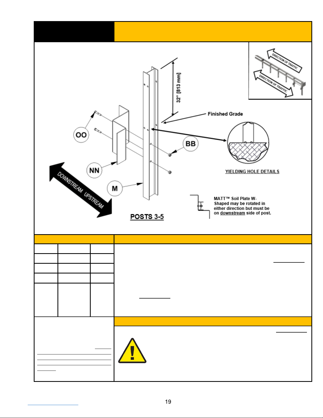
STEP 2C
MATT™ SYTP® With Soil Plate W-Shaped
Assembly for Posts 3 to 5
PARTS
INSTRUCTIONS
M
628271G
3 EA
Reference: SS-6288
1. Assemble the MATT™ Soil Plate W-Shaped (Part NN) to the downstream
side of the 6’-0” [1.829 m] MATT™ SYTP® (Part M) as shown above using
specified hardware (Parts BB, OO).
2. Tighten all threaded hardware to a snug position with a minimum of two (2)
bolt threads protruding beyond the nut.
3. Assemble the 6’-0” [1.829 m] MATT™ SYTP® with Soil Plate W-Shaped on
the downstream side of the post as shown above for Posts 3-5 at location
established in Step 1.
4. Ensure the center of the SYTP® Holes are approximately at finished grade
(+1”, -0”) [+25 mm, -0 mm].
BB
3340G
6 EA
NN
628269G
3 EA
OO
113660G
6 EA
Use only Trinity Highway parts that
are specified herein for the MATT™
for assembling, maintaining, or
repairing the MATT™. Do not
utilize or otherwise commingle
parts from other systems even if
those systems are Trinity Highway
systems.
WARNINGS
Ensure the MATT™ Soil Plate W-Shaped is on the downstream
side of MATT™ SYTP® 3-5.
Ensure the center of the SYTP® Holes are approximately at finished
grade (+1”, -0”) [+25 mm, -0 mm].
Ensure the Post spacing is as established in Step 1.
Ensure threaded hardware is tightened to a snug position with a
minimum of two (2) bolt threads protruding beyond the nut.
Failure to follow these warnings could result in serious injury or
death in the event of a vehicle impact with the system.
Table of contents
Other Trinity Highway Safety Equipment manuals


Popular Safety Equipment manuals by other brands


Petzl
Petzl PITAGOR TECHNICAL NOTICE

Climbing Technology
Climbing Technology SKT LIFELINE instruction manual

Steinberg Systems
Steinberg Systems SBS-HSD-9 user manual

Safety Engineering
Safety Engineering SELF BELAY Operation manual

MSA
MSA G1 SCBA operating manual

Kohlbrat & Bunz
Kohlbrat & Bunz UT 2000 manual