manuals.online logo
Brands
  1. Home
  2. •
  3. Brands
  4. •
  5. Tomahawk
  6. •
  7. Exercise Bike
  8. •
  9. Tomahawk Tomahawk X Series User manual

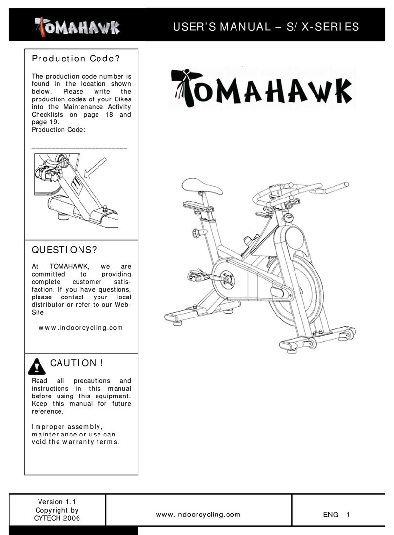
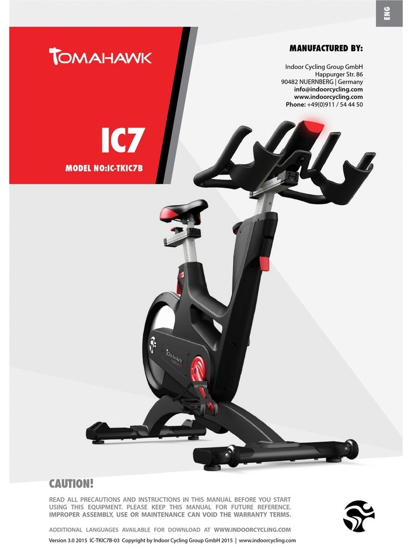
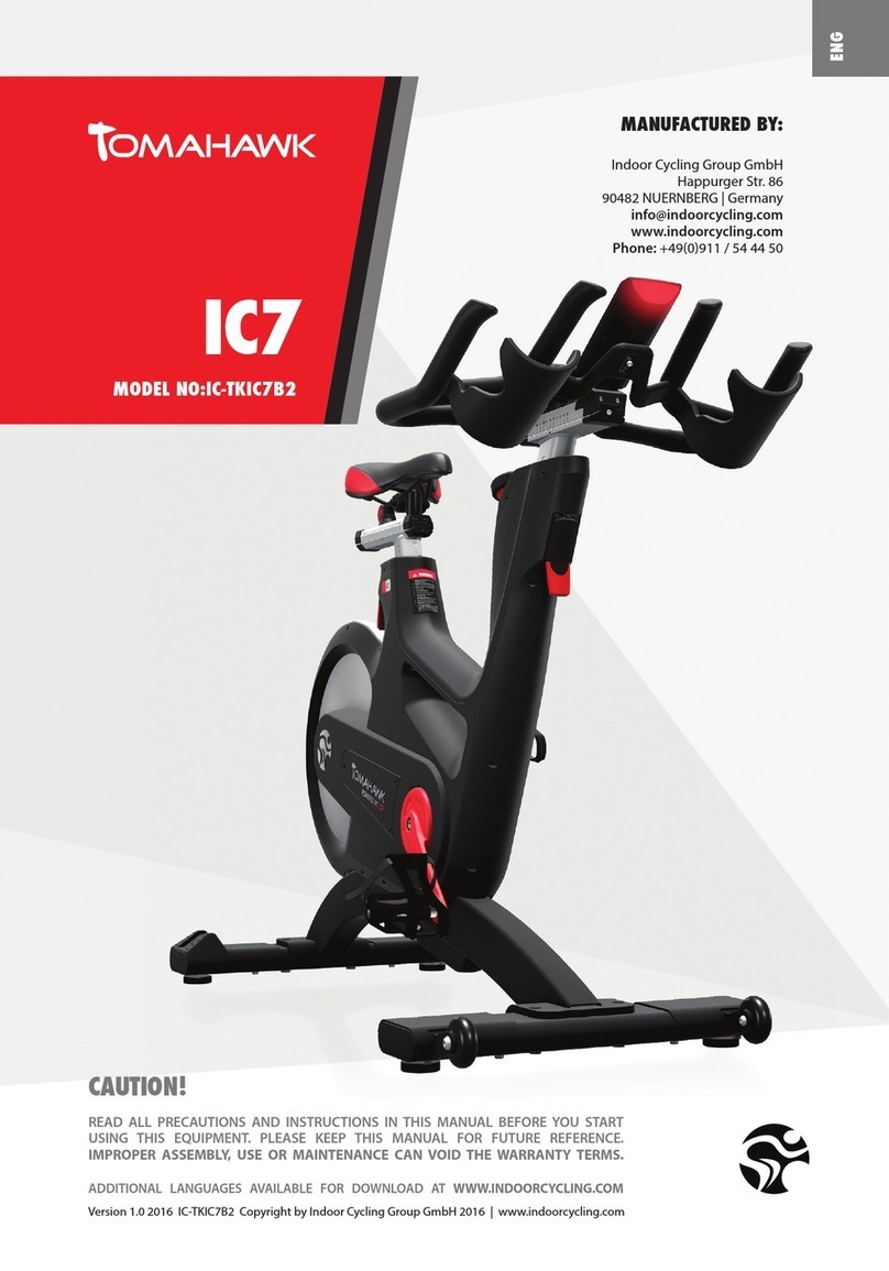
Tomahawk Tomahawk X Series User manual

Version 1.3
Copyright by
CYTECH GmbH 2008
ENG 1
www.indoorcyc ing.com
CAUTION!
Read a precautions and
instructions in this manua
before you begin using this
equipment. P ease keep this
manua for future reference.
Improper assembly, use
or maintenance can void
the warranty terms.
US R’S MANUAL
–
S
-
S RI S
Production Code?
The production code number
is found in the ocation
shown be ow. P ease write
the production codes of your
bikes into the Maintenance
Activity Check ists on page
16 and page 17.
Production Code:
-----------------------------
-
MATRIX Fitness Systems Corp.
1610 Landmark Drive
Cottage Grove, WI 53527
Toll-free: 866.693.4863
Local: 608.839.8686
www.matrixfitness.com/support/
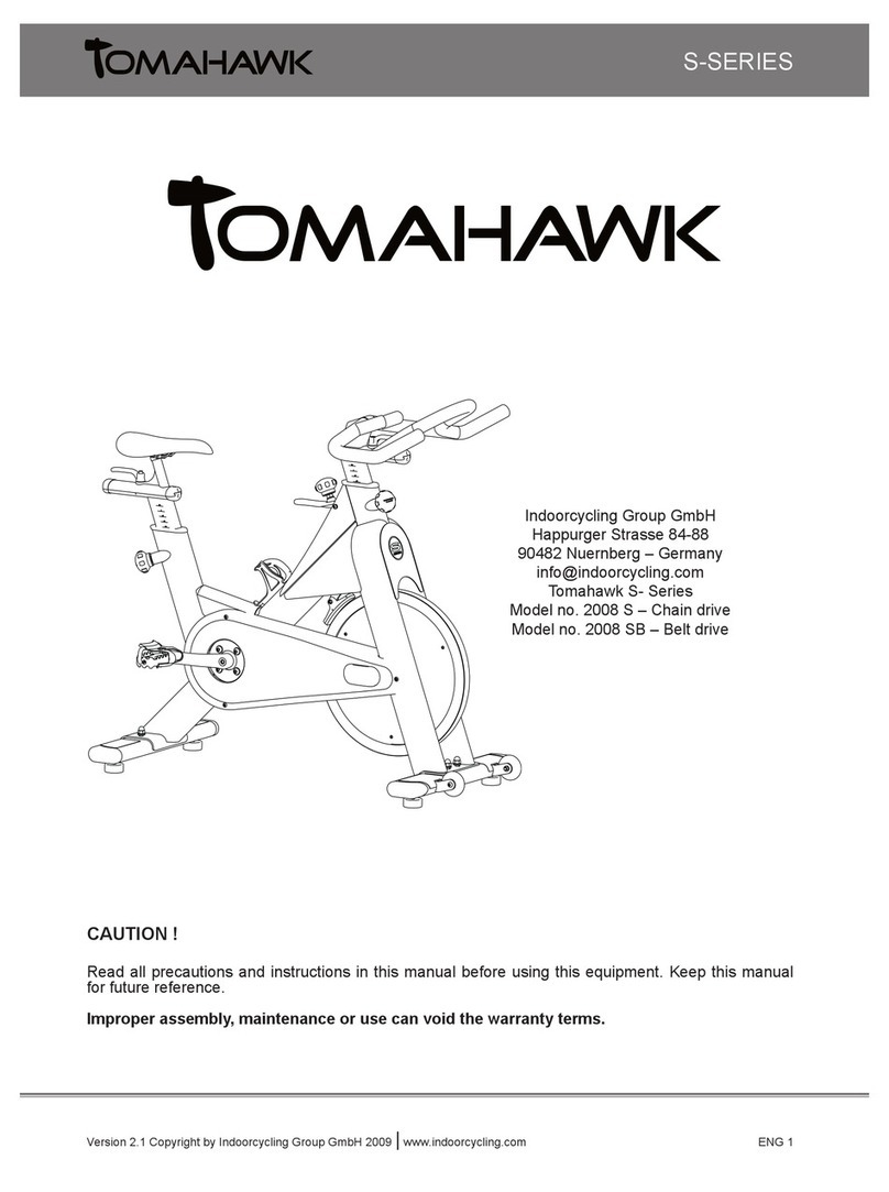
Tomahawk S-Series
Mode number 2008 SB – Be t drive
Version 1.3
Copyright by
CYTECH GmbH 2008
ENG 2
www.indoorcyc ing.com
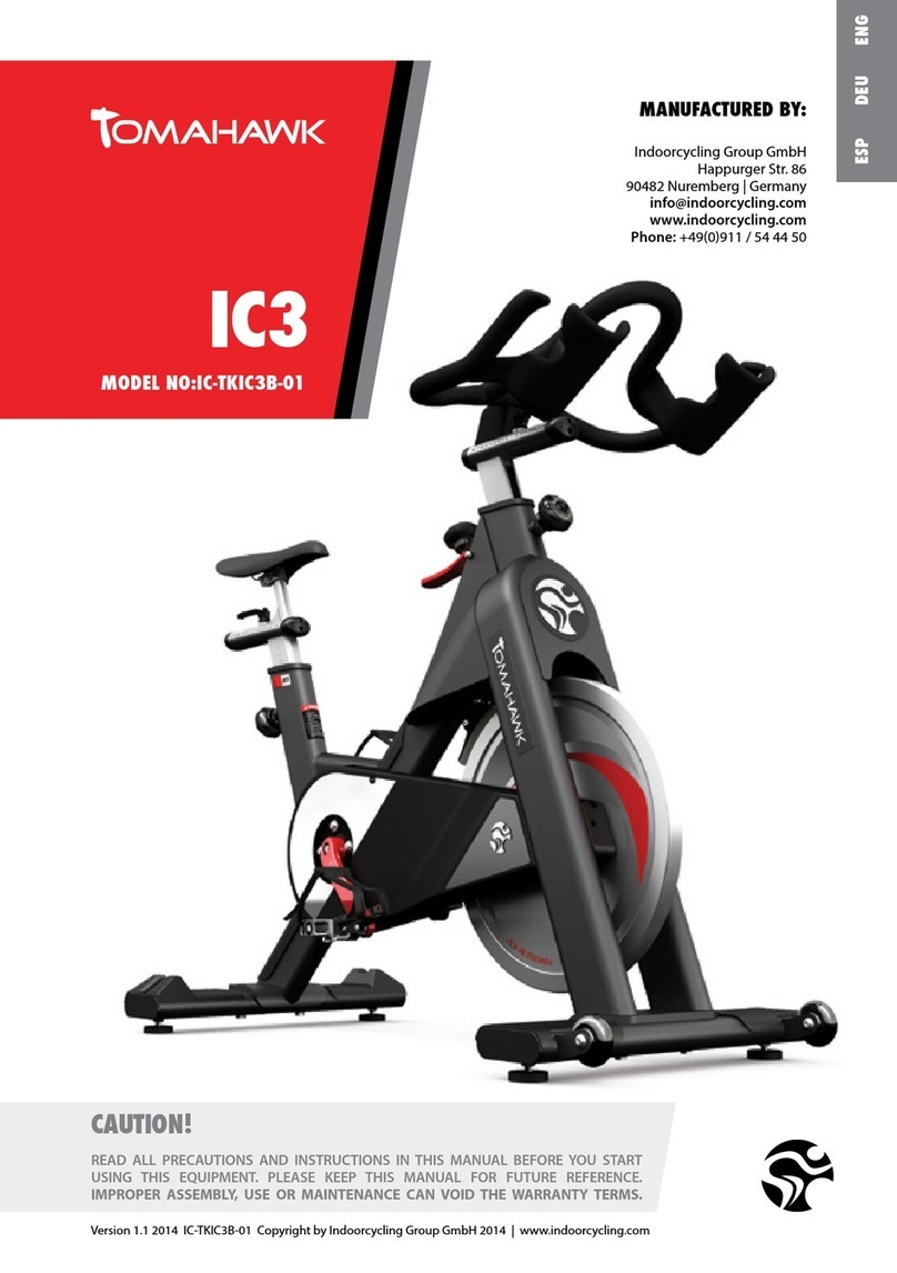
< Important precautions page 3
< Before you begin / component groups in carton page 4
< How to assemb e the Indoor Cyc e page 5-8
< How to adjust the Indoor Cyc e page 9-10
< Resistance adjustment page 11
< How to move the Indoor Cyc e page 11
< Preventive maintenance page 12-16
< Dai y maintenance page 12
< Week y maintenance page 12
< Bi-week y maintenance page 12-13
< Month y maintenance page 14
< Be t drive system, wearing parts page 15-16
< Maintenance Activity P an & Check ists page 17-18
< Exp osion drawings of structura components page 19-24
< Spare part reference ist page 25
< Limited warranty S-Series page 26-27
Technical specifications:
The Tomahawk S-Series Bike is according to EN 957 a C ass S product for
professiona and / or commercia use. Such training equipment is intended for the
use in trainings areas of organizations such as fitness c ubs or sport associations,
where access and contro is specia y regu ated by the person who has the ega
responsibi ity.
Foot print: 55 x 115 cm / 22 x 46 inch
Weight of bike: 60 KG / 130 Lbs
Max sadd e height: 110 cm / 43.5 inch
Max hand ebar height: 110 cm / 43.5 inch
Max user weight: 130 KG / 287 Lbs
The bike is designed to accommodate most users from 150 to 205 cm / 59 to 81 inch
body height
TABL OF CONT NTS
The Tomahawk
team thanks you for be ieving in our promise to
provide you the best in indoor cyc ing and make you part of the
Tomahawk Difference.
US R’S MANUAL
–
S
-
S RI S
Version 1.3
Copyright by
CYTECH GmbH 2008
ENG 3
www.indoorcyc ing.com
1. It is the so e responsibi ity of the
owner to ensure that a users of the
indoor cyc e are informed of a
warnings and precautions by an
authorized trainer or instructor prior to
use.
2. Operate and maintain the indoor cyc e
on y as described in this manua and
after proper assemb y and functiona ity
check (see page 5-10).
3. Keep the indoor cyc e indoors, away
from moisture and dust. Do not p ace
the indoor cyc e in a garage or covered
patio or near water.
4. P ace the indoor cyc e on a eve
surface. To protect the f oor or carpet
from damage, p ace a mat beneath the
indoor cyc e. Make sure that there is
adequate room around the indoor
cyc e to mount, dismount, and operate
it.
5. Regu ar y inspect and proper y tighten
a parts of the indoor cyc e as
recommended in this manua . P ease
rep ace defective parts immediate y
and do not use the bike unti repair is
performed. On y use origina parts
from the manufacturer
6. Chi dren under the age of 18 shou d
on y be a owed use of the indoor cyc e
with parenta approva and if guided by
a specia y trained instructor.
7. The indoor cyc e shou d not be used by
persons weighing more than 290
bs/130 kg.
8. A ways wear appropriate ath etic
c othes and shoes whi e operating the
indoor cyc e. Do not wear oose c othes
that cou d become caught on the
indoor cyc e or shoes with oose aces.
9. Before using the indoor cyc e, make
sure that you are fami iar with the
setup/operation of the indoor cyc e
(see pages 9-12).
10. The indoor cyc e does not have an
independent y moving f ywhee
(whee ); the peda s wi continue to
move together with the f ywhee unti
the f ywhee stops.
11. A ways regu ate the f ywhee
resistance so that your peda ing
motion is contro ed (see page 9-12).
12. Keep your back straight whi e using
the indoor cyc e; do not arch your
back.
13. If you fee pain or dizziness whi e
exercising, stop immediate y, rest and
coo down and consu t a physician.
14. If rep acement parts are needed, use
on y manufacturer supp ied parts.
WARNING!
To reduce the risk of serious injury, read the fo owing important precautions and
information before operating the indoor cyc e.
US R’S MANUAL
–
S
-
S RI S
IMPORTANT PR CAUTIONS
WARNING:
Before beginning any exercise program, consu t your physician. This is especia y
important for persons over the age of 35 or persons with pre-existing hea th prob ems.
Read a instructions before using. Be aware that incorrect or extensive training may
resu t in serious hea th injuries. The manufacturer assumes no responsibi ity for
persona injury or property damage sustained by or through the use of this product
.
Version 1.3
Copyright by
CYTECH GmbH 2008
ENG 4
www.indoorcyc ing.com
Dear Customer,
Congratu ations on se ecting the TOMAHAWK Indoor Cyc e. The TOMAHAWK Indoor Cyc e
offers an impressive array of features designed to enhance cardiovascu ar fitness, tone
musc es, and deve op endurance. Whether users are beginners or experienced ath etes, the
indoor cyc e offers workouts that wi he p users to reach their individua fitness goa s.
IMPORTANT: Read this manual carefully before assembling or
using the indoor cycle. If you have questions after reading this manua , p ease
contact your oca distributor or refer to the website www.indoorcyc ing.com. Before reading
on, p ease fami iarize yourse f with the parts that are abe ed in the drawing be ow.
B FOR YOU B GIN
US R’S MANUAL
–
S
-
S RI S
Tools needed for assembly:
open end spanner: 17/19mm, 13/15mm,
A en key: 3mm, 6mm
Hand e
bar assemb y
•hand ebar upper part
•vertica hand ebar stem
Front stabi izer bar
•eve ing feet
•transport whee s
•protection p ates
Seat post
assemb y
•adjustment knob
•horizonta sadd e support
•
vertica
seat
stem
Combi peda
•toe c ip
•toe strap
•binding system
Rear stabi izer bar
•eve ing feet
•protection p ates
Stabi izer mounting kit
•4 bo ts
•4 cap nuts
•4 stain ess stee washers
•8 p astic washers
•2 PVC gaskets
Version 1.3
Copyright by
CYTECH GmbH 2008
ENG 5
www.indoorcyc ing.com
Due to the weight of the indoor cycle, it is recommended that two people
perform the assembly. Set the cyc e in a c eared area and remove a packing
materia s; do not dispose of the packing materia s unti assemb y is comp eted.
1. Identify the rear stabi izer. Orient
the rear stabi izer so the widest parts
of the stabi izer end caps (A) are at
the rear.
Whi e a second person ifts the rear of
the frame, attach the rear stabi izer to
the frame with two M10 x 60mm bo ts
(B), four M10 washers, a stabi izer
gasket (C), two p astic washers (D),
and two M10 cap nuts as shown.
2. Orient the front stabi izer so the
widest parts of the stabi izer end caps
(A) are at the front.
Whi e a second person ifts the front
of the frame, attach the front
stabi izer to the frame with two M10 x
60mm bo ts (B), four M10 washers, a
stabi izer gasket (C), two p astic
washers (D), and two M10 cap nuts.
It is important that the plastic
washers (D) and PVC gasket (C)
used on front and rear stabilizers
are mounted in the correct
manner and used to prevent
direct contact of metal surfaces
HOW TO ASS MBL TH INDOOR CYCL
US R’S MANUAL
–
S
-
S RI S
To avoid damaging the rear stabi izer, do not
over tighten the cap nuts.
To avoid damaging the front stabi izer,
do not over tighten the cap nuts.
1
2
D
C
A
B
D
C
A
B
Version 1.3
Copyright by
CYTECH GmbH 2008
ENG 6
www.indoorcyc ing.com
Do not over tighten the adjustment
knob. Make sure the pin of the
adjustment knob is fu y engaged and
sadd e post does not s ide whi e riding.
4. Loosen the M8 bo t on the
ower side of the a uminium
sadd e bracket (A) severa turns
without removing it. Next, turn
the upper part of the sadd e
c amp (B) one quarter of a turn,
and set the rai s of the sadd e in
the grooves of the ower sadd e
c amp. Then, ift the upper sadd e
c amp, turn it back to its origina
position, and set it on top of the
rai s. Fina y, firm y retighten the
bo t and make sure that the
sadd e is mounted in its most
horizonta position at the midd e
of the rai .
3
4
M8
Bolt
B
US R’S MANUAL
–
S
-
S RI S
Stop
mark
3. Turn the rear adjustment knob
(A) counter c ockwise and pu the
adjustment knob to insert the
sadd e post (B) into the frame.
Next, bring the sadd e post to the
desired height, re ease the
adjustment knob so the pin
engages into the ho es of the
sadd e post. Then turn the
adjustment knob c ockwise to
retighten unti it is snug. Then
p ace the horizonta sadd e
support (C) into the s ider bracket
and connect it from beneath with
the sma adjustment knob (D).
P ease don’t adjust the height of
the vertica sadd e support
beyond the stop mark to avoid
instabi ity.
C
D
B
A
A
Version 1.3
Copyright by
CYTECH GmbH 2008
ENG 7
www.indoorcyc ing.com
5. Orient the parts needed to
mount the hand ebar. Turn the
front adjustment knob (A) counter
c ockwise and pu the adjustment
knob to insert the vertica
hand ebar post (B) into the frame.
Next, bring the hand ebar post to
the desired height, re ease the
adjustment knob so the pin
engages with the ho es of the
vertica stem and turn the
adjustment knob c ockwise to
retighten unti it is snug.
P ease don’t adjust the height of
the vertica sadd e support beyond
the stop mark to avoid instabi ity.
6. Set the stop b ock (C) into the
indicated ho e in the ower part of
the hand ebar s ider. Next, oosen
the adjustment ever hand e (D) in
the hand ebar s ider.
7. Remove the front grub screw ( )
from the upper part of the
hand ebar s ider (F). S ide the
hand ebar onto the hand ebar post
unti it stops.
5
6
7
US R’S MANUAL
–
S
-
S RI S
Stop mark
Do not over tighten the adjustment knob.
Make sure the pin of the adjustment knob
is fu y engaged and hand ebar post does
not s ide whi e riding.
A
B
C
D
F
Version 1.3
Copyright by
CYTECH GmbH 2008
ENG 8
www.indoorcyc ing.com
8. Reattach the front grub screw
back into the hand ebar unti the
end of the grub screw ( ) a most
touches the hhand ebar post.
Fina y, s ide the hand ebar to the
desired position and retighten the
adjustment knob.
9. Identify the right peda .
Carefu y insert the right peda into
the crank arm by hand turning it
c ockwise, assuring that it is
a igned horizonta y. Using a
15mm peda wrench, firm y tighten
the right peda c ockwise into the
right crank arm. Repeat the same
procedure for the eft peda but in a
counter c ockwise motion.
The manufacturer recommends
the use of semi loctite to mount
the pedals and to avoid pedals
becoming loose while riding.
8
9
US R’S MANUAL
–
S
-
S RI S
10. Make sure that all parts are
properly tightened and that the
brake pad is thoroughly soaked
with lubricant (WD-40) B FOR
the indoor cycle is used. Also
make sure there is a space
(approx. as thin as a credit
card) between the brake pad
and flywheel on the lowest
resistance setting. This
precaution will avoid extensive
wear on the brake pad. To
protect the floor or carpet,
place a mat under the indoor
cycle.
10
Version 1.3
Copyright by
CYTECH GmbH 2008
ENG 9
www.indoorcyc ing.com
Straps
The indoor cyc e can be adjusted for maximum comfort and exercise effectiveness.
The instructions be ow describe one approach to adjusting the indoor cyc e to ensure
optima user comfort and idea body positioning; you may choose to adjust the indoor
cyc e different y.
P DAL STRAP ADJUSTM NT
Sit on the sadd e and position your feet on the peda s, with the ba s of your feet
direct y above the spind es of the peda s (see the drawing be ow). Adjust the peda
straps so the toe c ips (cages) are snug but not too tight. Note: In the case of a bike
being fitted with combi-peda s, the peda s feature toe c ips on one surface and SPD
c eats on the opposite surface. If desired, use the shoe c eats with cyc ing shoes
instead of the toe c ips.
SADDL H IGHT ADJUSTM NT
Sit on the sadd e and s ow y peda unti the right peda is in the owest position. Your
knees shou d be s ight y bent without a dropping of the hips. To avoid hyper
extending your knees, make sure that your legs are not completely straight.
HOW TO ADJUST TH INDOOR CYCL
US R’S MANUAL
–
S
-
S RI S
P ease do not adjust
sadd e height beyond
the stop mark on the
stem (see page 6)
P ease do not adjust
hand ebar height beyond
the stop mark on the
stem (see page 7)
Version 1.3
Copyright by
CYTECH GmbH 2008
ENG 10
www.indoorcyc ing.com
US R’S MANUAL
–
S
-
S RI S
HANDL BAR ADJUSTM NT
Begin with the top of the hand ebar at re ative y the same height or just s ight y
higher than the top of the sadd e (dotted horizonta ine A in the drawing be ow) and
at a neutra fore/aft position (see dotted vertica ine B in drawing be ow). If your
knees touch the hand ebars or if you experience back discomfort whi e peda ing for
extended periods of time, the height of the hand ebar can be adjusted. First,
dismount the indoor cyc e. Next, turn the front adjustment knob counter c ockwise,
s ide the hand ebar post up or down, and then retighten the adjustment knob.
B
A
Hand ebar
up-down
adjustment knob
Next, the horizonta position of the hand ebars shou d be adjusted. If the
hand ebars are too c ose to the sadd e, your breathing may fee restricted; if the
hand ebars are too far from the sadd e, you may experience back discomfort. To
adjust the horizonta position of the hand ebars, first dismount the indoor cyc e.
Check for proper hand ebar position by positioning your e bow so that it is touching
the front tip of the sadd e at a 90 degree ang e and checking that the fingertip of
your midd e finger is touching the hand ebar at the mid-point. If it is not as
described, then oosen the fore-aft adjustment knob and s ide the hand ebars
forward or backward unti your midd e finger is touching the hand ebar at the mid-
point, and then retighten the hand e.
The hand ebar offers a wide variety of hand positions for persona preferences.
Changing your hand position can change the ang e of your back, neck, and arms.
To minimize the stress on your musc es during your workouts, change your hand
position frequent y.
Hand ebar
fore – aft ( )
adjustment knob
Hand ebar
m
id
-
point
Version 1.3
Copyright by
CYTECH GmbH 2008
ENG 11
www.indoorcyc ing.com
R SISTANC ADJUSTM NT
The preferred level of difficulty in pedalling (resistance) can be regu ated in fine
increments by use of the resistance knob. To increase the resistance, turn the
resistance knob c ockwise. To decrease the resistance, turn the knob counter
c ockwise.
IMPORTANT: To stop the f ywhee (whee ) whi e peda ing, pu up the red
emergency hand e. The f ywhee shou d quick y come to a comp ete stop. P ease
make sure your shoes are fixed into the toe c ip or in case cyc ing shoes are used
your shoe c eat is connected to the peda binding whi e riding.
HOW TO MOV TH INDOOR CYCL
Due to the weight of the indoor cycle, it is recommended that two people
move it. Whi e one person ifts the back of the indoor cyc e, the second person
firm y ho ds the hand ebar and tips the indoor cyc e forward unti it ro s on the
whee s. Carefu y move the indoor studio cyc e to the desired ocation and then ower
it. CAUTION: To reduce the risk of injury, use extreme caution while moving
the indoor studio cycle. Do not attempt to move it over uneven surfaces and
make sure a safety space of a minimum of 20 inches to the nearest
equipment is redeemed.
If the indoor cyc e rocks
on the f oor after being set
down, turn the eve ing
feet (see diagram) underneath
the front or rear stabi izer unti
the rocking motion is e iminated.
Important: P ease do not unscrew
the eve ing feet more than ½ inch!
Resistance
k
nob
Red emergency
brake hand e
Leve ing
f
eet
US R’S MANUAL
–
S
-
S RI S
HOW TO OP RAT TH INDOOR CYCL
WARNING: The indoor cycle does not have a free moving flywheel (wheel); the pedals
will continue to move together with the flywheel until the flywheel stops. Reducing speed in a
controlled manner is required. To stop the flywheel immediately, pull up the red emergency brake
handle. Always pedal in a controlled manner and adjust your desired cadence according to your
own abilities. Pull the red emergency handle up = emergency stop
Version 1.3
Copyright by
CYTECH GmbH 2008
ENG 12
www.indoorcyc ing.com
Regular maintenance must be performed on the indoor cycle for optimal
performance and longevity. P ease read and fo ow a the instructions be ow. If the
indoor cyc e is not maintained as described, components may wear excessive y and the
indoor cyc e may become damaged. Improper maintenance wi void the warranty
terms. If you have questions about maintenance, contact your oca distributor or refer
to www.indoorcyc ing.com
Note: Many maintenance procedures require lubricant spray. Manufacturer
recommends WD40, Brunox or any other solvent free lubricant.
DAILY MAINT NANC
1. Make sure that the indoor cyc e is eve . If the indoor cyc e rocks on your f oor, turn
the eve ing feet underneath the front or rear stabi izer unti the rocking motion is
e iminated (see HOW TO MOVE THE INDOOR CYCLE on page 11).
2. After each user finishes exercising, the indoor cyc e shou d be disinfected and
c eaned to maintain a hygienic environment. First, app y a disinfectant spray to the
hand ebars and the sadd e. Using a int-free c oth, dry the hand ebars and the sadd e.
Next, app y a sma amount of disinfectant to a int-free c oth and c ean the adjustment
knobs and the adjustment hand es. Avoid using strong detergents on the indoor cyc e
frame.
W KLY MAINT NANC
1. App y a sma amount of the ubrication spray to a int-free c oth, and thorough y
c ean the frame, the hand ebar s ider and seat s iders, the f ywhee and the p astic parts
of the indoor cyc e.
2. (Picture A) For optima performance of the resistance
system, and to minimize wear on the brake pad, the
so vent free ubricant spray shou d be app ied to the
brake pad using the ubrication ho es on the p astic part
of the brake pad. If fuzz or int appears on the brake pad,
the brake pad has become too dry— ubricant spray shou d
be app ied more frequent y. Make sure brake pad is
thorough y soaked from end to end with ubricant spray.
Then, wipe off the excess.
BI-W KLY MAINT NANC
1. (Picture B) The indoor cyc e shou d not be used if the
emergency brake system is not working proper y. Whi e
sitting on the sadd e and peda ing, test the brake by
pu ing the emergency brake hand e upward. The
f ywhee shou d come to a quick and comp ete stop.
PR V NTIV MAINT NANC
US R’S MANUAL
–
S
-
S
RI S
A
B
Version 1.3
Copyright by
CYTECH GmbH 2008
ENG 13
www.indoorcyc ing.com
2. To maintain the easy adjustabi ity
of the sadd e post, the sadd e post
shou d be c eaned and ubricated.
Remove the sadd e post out of the
frame as described on page 6. App y a
sma amount of ubricant spray to a
int-free c oth, and c ean the sadd e
post (A). Next, app y a sma amount
of ubricant spray inside of the rear
frame s eeve. Then, reinsert the
sadd e post into the frame and adjust
it to the desired height. Next, oosen
the rear adjustment knob and s ide
the sadd e carriage as far backward as
possib e. App y a sma amount of
ubricant spray to a int-free c oth, and
c ean the top of the sadd e s ide (B).
Then, s ide the sadd e carriage as far
forward as possib e and c ean the top
of the sadd e s ide. Fina y, adjust the
sadd e to the desired position.
3. To maintain the easy adjustabi ity
of the hand ebar post, the hand ebar
post shou d be c eaned and ubricated.
Remove the hand ebar post out of the
frame as described on page 7. App y a
sma amount of ubricant spray to a
int-free c oth and c ean the hand ebar
post (A). Next, app y a sma amount
of ubricant spray inside of the front
frame s eeve.
Then, reinsert the hand ebar post into
the frame and adjust it to the desired
height. Next, oosen the front
adjustment ever hand e and s ide the
hand ebar carriage as far backward as
possib e. App y a sma amount of
ubricant spray to a int-free c oth, and
c ean the top of the hand ebar s ide
(B). Then, s ide the hand ebar
carriage as far forward as possib e
and c ean the top of the hand ebar
s ide. Fina y, adjust the hand ebar to
the desired position.
A
B
US R’S MANUAL
–
S
-
S RI S
2
3
A
B
Version 1.3
Copyright by
CYTECH GmbH 2008
ENG 14
www.indoorcyc ing.com
MONTHLY MAINT NANC
1. To maintain the smooth function
of the pop pin adjustment knobs
(A) which contro the vertica
hand ebar and sadd e
adjustments, the meta threads
must be frequent y ubricated.
To ensure proper functioning of the
ever hand es (B) which contro the
horizonta seat and hand e bar
adjustments, the meta threads must
be frequent y ubricated. App y a
sma amount of synthetic grease
(white ithium grease) to the thread.
2. To maintain the easy adjustabi ity
of the resistance system, the threads
on the ower end of the brake rod
shou d be ubricated.
First, turn the resistance knob
c ockwise unti it stops. Next, ook
under the right or eft side of the
frame and ocate the brake rod,
which has two ock nuts on its ower
end. App y a sma amount of
synthetic grease (white ithium
grease) to the threads on the brake
rod above the two ock nuts. Then,
turn the resistance knob counter-
c ockwise unti it stops.
PR V NTIV MAINT NANC
US R’S MANUAL
–
S
-
S RI S
1
2
A
B
Version 1.3
Copyright by
CYTECH GmbH 2008
ENG 15
www.indoorcyc ing.com
3
A
B
C
D
Right side
US R’S MANUAL
–
S
-
S RI S
The graphics below are of the right
side of the Bike in riding position
3a. Belt driven bike
Important: A loose belt will increase the risk of
injury due to slipping and a highly over-tightened
belt can cause damage to the ball bearings of the
drive system and lead to excessive wear.
Correcting the belt tension:
To correct a loose belt: To adjust the be t, pu
off the right and the eft maintenance covers (A).
Loosen the ax e nut (B) on both ends of the
f ywhee ax e two fu turns. Loosen the outer
adjustment nut (C) facing the head of the a en bo t
on each side of the f ywhee . Then, turn both (right
and eft sides) of the inner adjustment nuts (D) on
the inside of the f ywhee bracket 1/4 of a turn at a
time (upward on the R side and downward on
L side) unti the be t is proper y adjusted and does
not s ip. Make sure to turn both adjustment
screws exactly the same amount to avoid
misalignment of the flywheel.
Fina y, retighten the two outer adjustment nuts (C)
and the two ax e nuts (B), and reattach the
maintenance covers. To avoid damage to the
flywheel bearings, do not over tighten the
axle nuts (B). Unusua noises, roughness or
vibrations are indications that the be t has been
over tightened, the f ywhee or bottom bracket
bearings are damaged or that the f ywhee is at an
ang e.
3b. User safety
To ensure user safety, frequent y check if be t is
firm y tightened and does not s ip whi e riding
under a resistance oad. If the be t s ips, proceed
using the same technique as described above.
P ease note that a be t drive gear never shows s ack
but wi s ip if not proper y tightened. In case of a
misa ignment, the be t wi show extensive wear.
P ease check the wear on the be t every 3 months
of use and rep ace if necessary.
Please avoid getting lubrication fluid in
contact with the belt, the drive gear pulleys or
any component of the belt drive system since
this will highly increase the risk of slipping.
Version 1.3
Copyright by
CYTECH GmbH 2008
ENG 16
www.indoorcyc ing.com
4
5
US R’S MANUAL
–
S
-
S
RI S
A
4. The brake pad wi become worn as a
resu t of repeated use. The indoor cyc e
shou d not be used if the emergency
braking system is not working proper y
(see page 11)! Shou d you fee that the
resistance system’s functions are deficient,
it is essentia to fine-tune the resistance
system before the bike is used again!
P ease check the setting of the brake
system as fo ows: First turn the
resistance regu ator on the brake system
as far as it wi go to the eft (minimum
braking effect). If the setting is correct,
the brake pads shou d be f ush with the
f ywhee and bare y touching so that it is
possib e to cyc e with a hard y noticeab e
amount of resistance. Next, check the
brake pad for signs of wear. If the brake
pad does show signs of excessive wear,
thorough y soak the brake pad with
ubricant spray using the 2 ubrication
ho es (A), and then wipe off the excess.
5. Some parts of the indoor cyc e may
become oose as a resu t of repeated use.
Check peda s, toe c ips, and peda straps,
and make sure that they are proper y
tightened. Next, check a exposed screws,
bo ts, and nuts, and make sure that they
are proper y tightened. Fina y, check the
sadd e to make sure that it is not oose or
damaged.
Version 1.3
Copyright by
CYTECH GmbH 2008
ENG 17
www.indoorcyc ing.com
Activity Details
found on
page…
Daily Weekly Bi -weekly Monthly
Feet eve ing, disinfecting and c eaning
of the bike
11, 12 X
Servicing brake pads, detai ed c eaning
of the entire bike
11,16 X
Check emergency brake function 11, 16 X
C ean and ubricate sadd e and
hand ebar s iders / posts
13 X
Check adjustment knobs 14 X
Check brake system, ubricate 14-15 X
Check be t drive system 15 X
Check brake pad for signs of wear 16 X
Check peda s, toe c ip and straps for
signs of wear
16 X
Check a connections and fixings if they
are secure and correct y tighten
16 X
Examp es of maintenance p an charts for in-house service technicians:
(Examples of weekly / bi-weekly / monthly maintenance
Weekly Maintenance Checklist
Bike
No.
Production code
bike
Observations Action taken Result Name / date
1
2
3
4
5
6
7
8
9
10
11
12
13
14
15
16
17
18
19
20
21
22
23
24
25
Maintenance Activity
Plan & Checklists
US R’S MANUAL
–
S
-
S RI S
Version 1.3
Copyright by
CYTECH GmbH 2008
ENG 18
www.indoorcyc ing.com
Bi-Weekly Maintenance Checklist
Bike
No.
Production code
bike
Observations Action taken Result Name / date
1
2
3
4
5
6
7
8
9
10
11
12
13
14
15
16
17
18
19
20
21
22
23
24
25
Monthly Maintenance Checklist
Bike
No.
Production code
bike
Observations Action taken Result Name / date
1
2
3
4
5
6
7
8
9
10
11
12
13
14
15
16
17
18
19
20
21
22
23
24
25
MAINT NANC CH CKLISTS
US R’S MANUAL
–
S
-
S RI S
Version 1.3
Copyright by
CYTECH GmbH 2008
ENG 19
www.indoorcyc ing.com
SPAR PARTS
US R’S MANUAL
–
S
-
S RI S
Bottom bracket parts
01 40 CS 08
02 40 90
02 40
CRMO R SX 08
Part of 02 40 B
02 40 C 2RS
02
40 CMD 20 08
01
40 A2
02 40 CRMO L SX 08
Descriptions of parts on page 25
02 5
0
05 SX
Brake parts
02 5
0
03 A SX
02 5
0
03 B
02 5
0
06
02 5
0
04
02 5
0
01
02 5
0
02
02 5
0
A SX
Version 1.3
Copyright by
CYTECH GmbH 2008
ENG 20
www.indoorcyc ing.com
US R’S MANUAL
–
S
-
S RI S
01 40 08 ES 08
Flywheel
02 40 H L
Part of 02 40 B
02 40 02
Chain guard
02 42 04
02 42 02 SX 08
02 42 01 SX 08
02 42 03 SX 08
02 99
05
02 99 03
Descriptions of parts on page 25

Other manuals for Tomahawk X Series

1

This manual suits for next models

1

Other Tomahawk Exercise Bike manuals

Tomahawk Tomahawk X Series User manual

Tomahawk

Tomahawk Tomahawk X Series User manual

Tomahawk Home Series User manual

Tomahawk

Tomahawk Home Series User manual

Tomahawk IC3 User manual

Tomahawk

Tomahawk IC3 User manual

Tomahawk S Series User manual

Tomahawk

Tomahawk S Series User manual

Tomahawk IC-TKIC7B2 User manual

Tomahawk

Tomahawk IC-TKIC7B2 User manual

Tomahawk IC1 User manual

Tomahawk

Tomahawk IC1 User manual

Tomahawk Matrix 2008 EB User manual

Tomahawk

Tomahawk Matrix 2008 EB User manual

Tomahawk IC-TKIC7B User manual

Tomahawk

Tomahawk IC-TKIC7B User manual

Tomahawk IC-TKIC7B-01 User manual

Tomahawk

Tomahawk IC-TKIC7B-01 User manual

Tomahawk IC2 User manual

Tomahawk

Tomahawk IC2 User manual

Tomahawk S Series User manual

Tomahawk

Tomahawk S Series User manual

Tomahawk IC5 User manual

Tomahawk

Tomahawk IC5 User manual

Popular Exercise Bike manuals by other brands

Tunturi Star Fit E100 user manual

Tunturi

Tunturi Star Fit E100 user manual

Vision Fitness R2200HRT owner's guide

Vision Fitness

Vision Fitness R2200HRT owner's guide

Spirit CS800 owner's manual

Spirit

Spirit CS800 owner's manual

VIRTUFIT HTR 2.0 manual

VIRTUFIT

VIRTUFIT HTR 2.0 manual

Circuit Fitness AMZ-948BK-BT Assembly & owners manual

Circuit Fitness

Circuit Fitness AMZ-948BK-BT Assembly & owners manual

Tunturi GO BIKE 50 user guide

Tunturi

Tunturi GO BIKE 50 user guide

ICON Health & Fitness NordicTrack GX 4.7 user manual

ICON Health & Fitness

ICON Health & Fitness NordicTrack GX 4.7 user manual

Schwinn 250 owner's manual

Schwinn

Schwinn 250 owner's manual

ISE SY-8602 owner's manual

ISE

ISE SY-8602 owner's manual

Coopers 10414 Instructions for use

Coopers

Coopers 10414 Instructions for use

Kettler Ergometer E3 Assembly instructions

Kettler

Kettler Ergometer E3 Assembly instructions

NordicTrack NTIVEX70414.0 user manual

NordicTrack

NordicTrack NTIVEX70414.0 user manual

SportsArt Fitness C50U instruction manual

SportsArt Fitness

SportsArt Fitness C50U instruction manual

NordicTrack NTEX14807.1 user manual

NordicTrack

NordicTrack NTEX14807.1 user manual

NordicTrack CEX22522 user manual

NordicTrack

NordicTrack CEX22522 user manual

NordicTrack C7 Zl Bike Bedienungsanleitung

NordicTrack

NordicTrack C7 Zl Bike Bedienungsanleitung

BH FITNESS H495 Instructions for assembly and use

BH FITNESS

BH FITNESS H495 Instructions for assembly and use

Sunny Health & Fitness SF-B1877 user manual

Sunny Health & Fitness

Sunny Health & Fitness SF-B1877 user manual

manuals.online logo
manuals.online logoBrands
  • About & Mission
  • Contact us
  • Privacy Policy
  • Terms and Conditions

Copyright 2025 Manuals.Online. All Rights Reserved.