IS0802-00
11-08-18
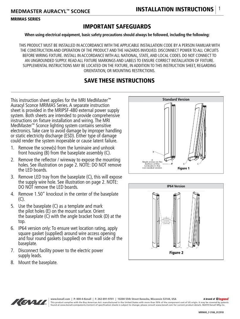
Wiring he AC Models
1. nsure that power is off.
2. Install conduit to conduit opening and tighten set screw.
3. Pull field wiring through conduit into enclosure/base.
4. Remove the threaded dome assembly by twisting it counterclockwise.
5. Remove the L D light engine assembly by removing 2 screws attaching the metal disk to the case.
6. Connect the black lead to 120-240VAC 50-60Hz phase (hot) side of the power source and the white
lead to the common (neutral) side of the AC power source. Connect the green wire to ground.
7. Select the mode of operation, either flashing or steady burn mode, via either internal dip switch or
external connections of the blue and yellow wires. See Table 1 for proper settings and connections.
No e: 1. Dip swi ches will override any ex ernal wire connec ions.
No e: 2. If he blue and yellow wires are no used cu off or cap wi h a wire nu .
In ernal Dip Swi ch Se ings for se ing modes of opera ion
Single flash 2 380mS On, 380ms Off
Double flash @200mS On, @00mS On, 900mS Off
Ex ernal Wire Connec ions for se ing modes of opera ion
Single flash 2 380mS On, 380ms Off
Double flash @200mS On, @00mS On, 900mS Off
The yellow and blue wires
can also be connec ed o PLC con roller for mode
ac iva ion. For a PLC he inpu vol age can be ei her be AC or DC, bu mus be grea er
han 100 vol s RMS and no more han 240 vol s RMS
8. Replace the L D light engine assembly and attach 2 screws.
9. Secure the dome to the base of the beacon.
10. Connect power to the beacon and test it for proper operation
Wiring 24 VAC/VDC Models (4375L-24)
1. nsure that power is off.
2. Install conduit to conduit opening and tighten set screw.
3. Pull field wiring (including external mode operation wiring, if applicable) through conduit into
enclosure/base.
4. Remove the threaded dome assembly by twisting it counterclockwise.
5. Remove the L D light engine assembly by removing 2 screws attaching the metal disk to the case.
6. Connect the black lead to 12-30VAC 50-60Hz phase (hot) or 12-30VDC positive DC side of the
AC/DC power source and the white lead to the common (neutral) side or negative DC side of the
AC/DC power source. Connect the green wire to ground.
7. Select the mode of operation, either flashing or steady burn mode, via either internal dip switch or
external connections of the blue and yellow wires. See Table 2 for proper switch settings and wire
connections.
