TOMMATECH TT400-80PMKB12-250 User manual

1
BIPV SOLAR PANEL
INSTALLATION
MANUAL

HEADQUARTER
Angerlweg 14
85748 Garching
Munich/Germany
Phone: +49 89 1250 36 860
Home: www.tommatech.de
E-mail: [email protected]

1
CONTENTS
1. INTRODUCTION......................................................................................................................................4
2. CODES AND REGULATIONS................................................................................................................4
3. GENERAL.................................................................................................................................................4
3.1 Product Identification.......................................................................................................................5
3.2 General Safety..................................................................................................................................5
3.3 Electrical Performance Safety..........................................................................................................5
3.4 Operating Safety...............................................................................................................................6
3.5 Fire Safety........................................................................................................................................6
4. INSTALLATION CONDITION................................................................................................................7
4.1 Installation Position and Working Environment...............................................................................7
4.2 Tilt Angle Selection..........................................................................................................................7
5. MECHANICAL INSTALLATION...........................................................................................................8
5.1 Conventional Requirement...............................................................................................................8
5.2 Installation Method...........................................................................................................................9
5.2.1 Description of the installation position..............................................................................11
6. ELECTRICAL INSTALLATION............................................................................................................12
6.1 Electrical Property..........................................................................................................................12
6.2 Cables and Wiring..........................................................................................................................13
6.3 Connectors .....................................................................................................................................13
6.4 Bypass Diodes................................................................................................................................14
7. OPERATION AND MAINTENANCE ...................................................................................................17
7.1 Cleaning.........................................................................................................................................17
7.2 Visual Inspection of Solar panels...................................................................................................17
7.3 Inspection of connector and cable..................................................................................................17
8. APPLICABLE PRODUCTS....................................................................................................................18

2
1. INTRODUCTION
TommaTech GmbH (hereafter referred to as “TommaTech”) is a hi-tech company engaged in the
development, research, production, sales and service of crystalline silicon wafers, solar cells, solar
panels, and photovoltaic solutions.
TommaTech established strong and competitive partnerships in the photovoltaic field in Europe and in
Far East with companies that value quality and reliable solar power generation. We will support you
with our strong and experienced team for the purchase of solar equipment as well as turnkey projects
with a wide product range and variety of methods and procedures. Our mission is to make human life
more sustainable, making the difference in the industry through unique customer focus and high
quality, thus progressing confidently towards becoming a world leader in our own sector.
2. CODES AND REGULATIONS
The mechanical and electrical installation of PV systems should be performed in accordance with all
applicable codes, including electrical and construction guidelines.
Such requirements may vary with the mounting location, such as building rooftop or motor vehicles
as well as with the system voltages. Please contact your local authorities for the corresponding
governing regulations in place.
3. GENERAL
The parts of our BIPV Solar Panels are indicated in the figure below:
Figure 1: BIPV Solar Panel Overview

3
3.1 Product Identification
Each solar panel has three labels providing the following information:
1. Nameplate. The name plate describes the product type, peak power, max. power point current,
max. power point voltage, open circuit voltage, short circuit current, as measured under standard
test conditions, certification marks, the maximum system voltage etc.
2. Current Classes. Solar panels are divided into three classes according to the maximum power
current: 1, 2 or 3 (3 means the highest current). This class is marked as a number on the pallets of
the solar panels. To achieve an optimal performance of the solar panels, it is recommended to only
connect solar panels with the same current class in a string.
3. Barcode: Each individual module has a unique serial number which is permanently attached to the
interior of the Modules and visible on the top front of the Module. The serial number has 12 digits.
From 1st to 2nd digits are the solar cell size code, and the 3rd and 4th are the corrected year code,
from 5th and 6th are the corrected month codes, digit 7 is a product specific optional number and
the numbers 8 to 12 show the serial number of a module. For example, 133414000001 means the
Module was assembled and tested in the January of 2021.
3.2 General Safety
TommaTech solar panels are designed to meet the requirements of IEC61215 and IEC61730, PV
module classification: Class II. Solar modules in this class may be used in systems that are operating
above 50VDC or 240W, where general access is anticipated.
When Solarmodules are mounted on rooftops, the roof must have a fire-resistant covering suitable for
this application. Rooftop PV systems should only be installed on roofs that can handle the additional
weight of al l PV system components, which has to be approved by a certified building specialist
or engineer through a structural analysis.
For your own safety, do not attempt to work on a rooftop until safety precautions have been identified
and taken including without limitation fall protection measures, ladders or stairways, and personal
protection equipment.
Foryourown safety, donotinstallorhandleModulesunderadverseconditions,includingwithout limitation
strong or gusty winds, and wet or frosted roof surfaces.
3.3 Electrical Safety
Photovoltaic modules produce DC electricity when exposed to light and therefore can produce an
electrical shock or burn. Please note that DC voltage of 30 Volts or higher is potentially lethal.
Furthermore, modules produce voltage even when not connected to an electrical circuit or load. Please
use insulated tools and rubber gloves when working with Modules in sunlight.
Modules have no on/off switch and can be rendered inoperative only by removing them from sunlight,
or by fully covering their front surface with cloth, cardboard, or other completely opaque materials,
or by working with modules face down on a smooth, flat surface.
In order to avoid arcs and electrical shock, please do not disconnect electrical connections under load.
Faulty connections can also result in arcs and electrical shock. Consequently, please keep connectors
dry and clean, and ensure regularly that they are in proper working condition. Never insert metal
objects into the connector or modify them in any way to secure an electrical connection.
To avoid and or water vapor entering which may cause connection and safety issues, the modules
need to be installed and connected once they are taken out from the carton box. Please note that the
pollution from sand, dust and water will result in arcs and electrical shocks of connectors.
Reflection from snow or water can increase sunlight and therefore boost current and power. In
addition, colder temperatures can substantially increase voltage and power.
If the glass or other material is damaged, please wear personal protection equipment and separate
affected modules from the circuit. Work only under dry conditions and use only dry tools. Do not
handle modules when they are wet unless wearing appropriate protective equipment. If you need to
clean solar panels, please follow the cleaning steps as outlinedaaaq in the manual.

4
3.4 Operating Safety
Do not open packagesof TommaTech solar panels during transportation andstoringuntil theyare ready
to be installed. At the same time please protect the package from damages. Do not allow the pallets of
solar panels to fall over directly.
Do not exceed the maximum height of pallets to be stacked as indicated on the pallet packaging. Store
pallets in a ventilated, rain-proof, and dry location until the solar panels are ready to be installed. Do
not lift the solar panels by grasping the module's junction box or electrical cable under any condition.
Do not stand or step on the solar panels.
Do not drop the solar panels on other solar panels.
Do not place any heavy objects on the solar panels.
Be cautious when setting the solarpanelsdown on asurface, especially on thecorner of the solar panels.
Inappropriate transportation and installation may break the solar panels.
Do not attempt to disassemble the solar panels, and do not remove any attached nameplates or
components from the solar panels.
Do not apply paint or adhesive to the solar panels surface.
3.5 Fire Safety
Solar rooftop installations might affect the building’s fire safety. Consequently, please consult your
local authority for guidelines and requirements for building or structural fire safety. TommaTech
modules have been listed as Safety- Class C according to IEC 61730-2 standard. For roof installations,
solar panels should be mounted over a fire-resistant covering suitable for this application, with adequate
ventilation between the module and the mounting surface. Improper installation may create hazards in
the event of a fire.
Solar panels should not be installed on structures and products made of plastic and similar materials
that are able to catch fire. In order to maintain the fire class rating, the distance between the modules
surface and the roof surface shall be at least 10cm.
Appropriate components such as fuses, circuit breakers, surge arresters and grounding connectors must
be used to meet the requirements as specified in regulations, communiqués, decrees, specifications,
etc., put into effect by the relevant official institutions and organizations. Any string or optimizer
connector to be connected with the solar panel must be the same brand and model as the connector on
the solar panel.
Do not install solar panels in places where flammable-explosive chemical products, gases and similar
products can be found.
Panels that have not been installed in accordance with these standards and conditions will be out of
warranty, the installation will be installed contrary to the installation manual, and the manufacturer will
not be responsible for any risks or problems that may occur. In this context, the manufacturer does not
have any liability, including compensation for damages or other consequences if the solar panels are
handled contrary to the instructions as outlined in this installation and assembly manual.
4. INSTALLATION CONDITIONS
4.1 Installation Position and Working/Operational Environment
TommaTech solar panels are intended for use in terrestrial applications and only for outside installation.
Do not use mirrors or other magnifiers to concentrate sunlight onto the solar panels.
Solar panels must be mounted on appropriate mounting structures positioned on suitable buildings, the
ground, or other structures suitable for solar panels (e.g., carports, building facades or PV trackers).
Solar panels must not be installed in locations where they could be submerged in water.
The temperature limits are defined as the monthly average high and low of the installation site. The
limit operating temperature should be -40°C (-40°F) and 85°C (185°F).

5
Ensure that the solar panels are not subject to wind or snow loads exceeding the maximum permissible
loads. The solar panels should be installed in a location where there is no shading throughout the year.
Ensure there is no obstacle to block light near the installation site.
Lightning protection is recommended for PV systems that are to be installed in locations with high
probability of lightning strikes.
Do not use solar panels near equipment or in locations where flammable gasses may be generated or
collected.
The solar panels can be installed at a maximum 2000m altitude.
TommaTech solar panels must neither be installed nor operated in areas where hail, snow, sand, dust,
air pollution, soot, etc., are excessive. Solar panels must not be sited in locations where aggressive
substances such as salt, salt mist, saltwater, chemically active vapors, acid rain or any other type of
corrosive agent could affect the safety and/ or performance of the solar panels.
Please implement appropriate measures to ensure the performance and safety of the solar panels when
they are installed or operated in the areas with heavy snow, extremely cold climates, strong winds, on
islands, in a desert where the solar panels are prone to produce salt fog, or near water.
4.2 Tilt Angle Selection
The tilt angle of the solar panels is measured between the surface of the solar panels and a horizontal
ground surface. The solar panels generate maximum power output when facing the sun directly.
In the northern hemisphere, solar panels should typically face south, while in the southern hemisphere,
solar panels should typically face north.
For detailed information on the best installation angle, please refer to standard solar photovoltaic
installation guides or consult a reputable (local) solar installer or systems integrator.
Dust building up on the surface of the solar panels can impair with the solar panels’performance.
TommaTech recommends installing the solar panels with a tilt angle of at least 10 degrees, making it
easier for dust to be washed off by rain.
5. MECHANICAL INSTALLATION
5.1 General Requirements
Please ensure that the installation method and support structure of solar panels is strong enough to
enable the solar panels to withstand all load conditions, which must be guaranteed by the installer. The
installation support structure must be tested by a third-party organization with static mechanical
analysis ability, according to the local national or international standards such as DIN1055 or
equivalent.
The solar panels mounting structure must be made of durable, corrosion-resistant, and UV-resistant
materials and the solar panels must be securely attached to the mounting structure. In regions with
heavy snowfall, select the height of the mounting system, so that the lowest edge of the solar panels is
not covered by snow for any period of time. In addition, please ensure that the lowest portion of the
solar panels is placed high enough so that it is not shaded by plants or trees or damaged by flying sand.
When the solar panels are installed parallel to the surface of the building wall or roof, a minimum
clearance of 10 mm between the solar panels and the surface of the wall or the roof is required to allow
air circulation behind the solar panels and to prevent wiring damages.
Do not attempt to drill holes in the glass surface of the solar panels.
Before installing solar panels on a roof, ensure that the roof construction is suitable. In addition, any
roof penetration required to mount the solar panels must be properly sealed to prevent leaks.
Always keep the panel free from foreign objects or mounting elements, which could come into contact
with the panel, especially when the panel is under mechanical load.
TommaTech solar panels have been certified for a maximum static load on the back-side of 2400Pa
(i.e. wind load) and a maximum static load on the front side of 2400Pa (i.e. wind and snow load),
depending on the solar panels type (please refer to Figure 4 for detailed installation method). These
load values are maximum. The design load for 1600Pa is 1600 a with a safety factor is 1.5.

6
5.2 Installation Method
TommaTech solar panels can be installed using a suitable clamping system or according to the
following examples which are recommended to the TTKB sseries. If you cannot mount the solar panels
according to these instructions, please consult TommaTech in advance since the alternative mounting
method must be approved by TommaTech, otherwise it may damage solar panels, and void the
warranty.
Figure 2: Mounting Cross-section
Figure 3: Solar Terrace or Carport Design

7
5.2 Description of the installation position
The low/normal level of load condition is applicable to the installation in most of environmental
conditions: the maximum static test load on the back of the modules is 2400 Pa (i.e., wind load), and
the maximum static test load on the front of the modules is 2400 Pa (i.e., wind and snow load).
The high level of load condition is applicable to the installation in harsher environmental conditions
such as storm, heavy snow, etc. the maximum static test load on the back of the modules is 2400Pa
(i.e., wind load) and the maximum static test load on the front of the modules is 2400Pa (i.e., wind
and snow load), depending on the pressure level that it would endure according to IEC standard.
For dynamic loads, such as wind, the safety factor needs to be increased by 3 times. It means that the
maximum dynamic load is 800 Pa when the wind speed is less than 130km/h.
Figure 3: Installation Methods
6. ELECTRICAL INSTALLATION
6.1 Electrical Characteristics
Rated electrical characteristics such as lsc, Voc and Pmax are measured within +/- 3% measurement
uncertainty at standard test condition (STC): 1000W/m²irradiance, 25°C Cell Temperature and 1.5 Air
Mass. Under normal conditions, photovoltaic solar panels may produce higher currents and/or voltages
than reported at Standard Test Conditions. Accordingly, the values of short circuit current, lsc, and
open circuit voltage, Voc, marked on solar panels should be multiplied by a factor of 1.25 when
determining component voltage ratings, conductor capacities, fusing sizes, and size of controllers
connected to the solar panels.
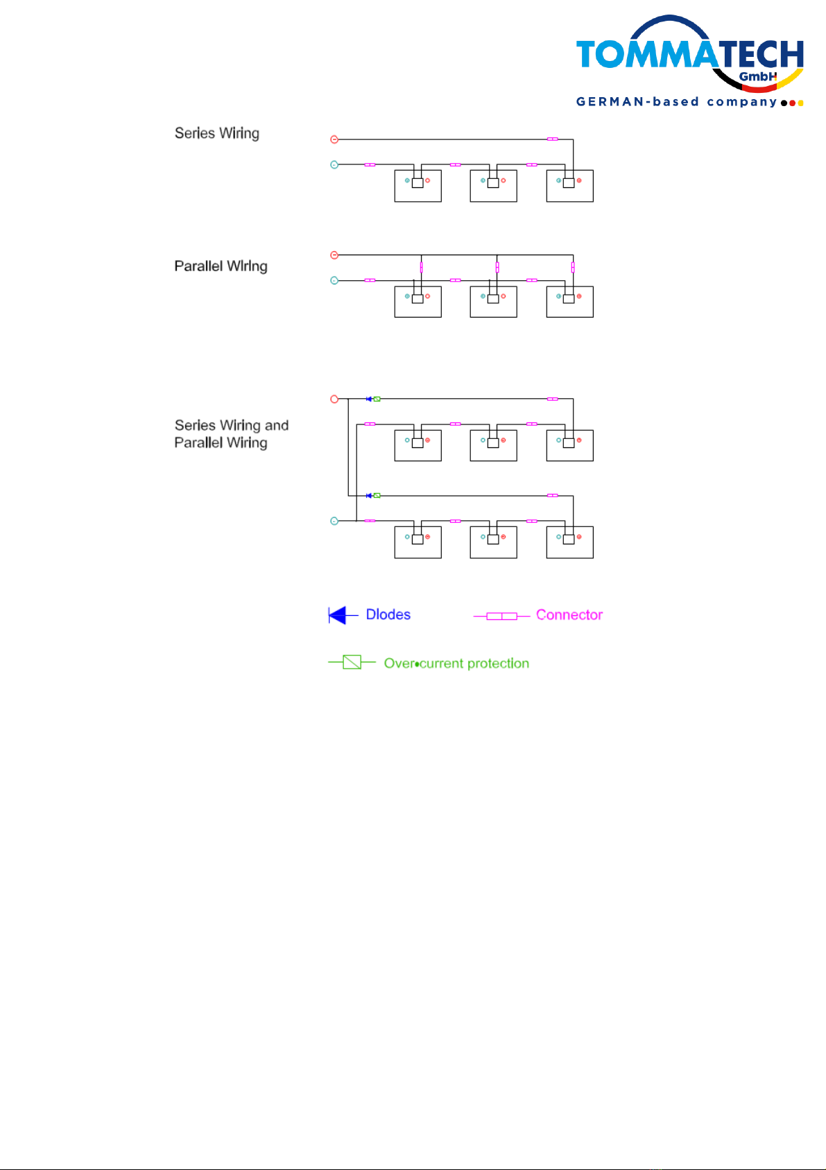
Voltages are additive when solar panels are connected in series, while the currents are additive when
they are connected in parallel, as illustrated in Figure 5 on the next page.
The number of panels which can be connected to a string is calculated according to the voltage of the
junction box of the panels, the NOCT value of the panel, the DC input voltage of the inverter to be used
and the ambient temperature of the location of the plant. Solar panels with different electrical
characteristics must not be connected directly in series.
System Voltage ≥ N *Voc [1+TCVoc* (Tmin-25)]
N = Number of panels in the series
Voc = Open Circuit Voltage (data on product label or datasheet)
TCVoc = Temperature coefficient of open circuit voltage (data on product label or datasheet)
Tmin = Minimum ambient temperature
8
Figure 4: Electrical Diagrams of Series and Parallel Connection
Please note that the maximum number of solar panels which can be connected in a series string must
be calculated in accordance with applicable regulations in such a way that the specified maximum
system of the solar panels and all other electrical DC components will not be exceeded in open- circuit
operation at the lowest temperature expected at the PV system location (The maximum system voltage
of TommaTech solar panels is 1000VDC/ 1500VDC according to the safety standards of IEC61730).
An appropriately rated over-current protection device must be used when the reverse current could
exceed the value of the maximum fuse rating of the solar panels. An over-current protection device is
required for each string if more than two strings are connected in parallel, as illustrated in Figure 4
above.
6.2 Cables and Wiring
Please note that the junction boxes at the back of the solar panels have been designed to enable easy
and reliable connection in series with IP67 protection grade. Each module has two single-conductor
wires, one positive and one negative, which are pre-wired inside the junction box. The connectors at
the opposite end of these wires allow easy series connection of adjacent solar panels by firmly inserting
the positive connector of a module into the negative connector of an adjacent module until the connector
is fully seated.
For field wiring please use cables with suitable cross-sectional areas that are approved for operation at
the maximum short circuit current of the solar panels. TommaTech recommends to only use UV

9
resistant cables which are qualified for direct current (DC) wiring in PV systems. The minimum wire
size should be 4mm². For example, a solar cable according to the specifications below is recommended:
The cable of the junction box is identified as L as shown in Figure 6 below. L for TommaTech standard
module is 1000/1200 mm, L for half-cut module is 300/1200 mm and L for bifacial module is 300/1200
mm. L for special modules may vary depending on the situation. Please consider the cable length before
designing the wiring layout.
Figure 5: Junction Box
Cables should be fixed to the mounting structure in such a way that mechanical damage of the cable
and/or the modules is avoided. Do not apply stress to the cables. For fixing, use appropriate means,
such as sunlight resistant cable ties and/or wire management clips specifically designed to attach to the
support structure. While the cables are sunlight resistant and waterproof, where possible, avoid direct
sunlight exposure and water immersion of the cables.
6.3 Connectors
Keep connectors dry and clean. Do not attempt to make an electrical connection with wet, soiled, or
otherwise faulty connectors. Avoid sunlight exposure and water immersion of the connectors. Avoid
allowing connectors to rest on the ground.
Faulty connections can result in arcs and electrical shocks. Please ensure that all electrical connections
are securely fastened and that all locking connectors are fully engaged and locked. The connectors can
only be unlocked with the tool PV-MS-PLS. Only the same type of connectors can be used for
installation.
6.4 By-Pass Diodes
The junction boxes installed at the back of TommaTech solar panels contain by-pass diodes wired in
parallel with the PV cell strings. In the case of partial shading, the diodes bypass the current generated
by the nonshaded cells, thereby limiting solar panels heating and performance losses.
By-pass diodes are not over-current protection devices but divert current from the cell strings in the
event of partial shading.
In the event of a known or suspected diode failure, installers or maintenance providers should contact
TommaTech. Never attempt to open the junction box by yourself.
7. OPERATIONS AND MAINTENANCE
It is necessary to perform regular inspection and maintenance of the solar panels, especially within
warranty scope. It is the user's responsibility to report to the supplier regarding the damages found
within 2 weeks.
7.1 Cleaning
The dust accumulated on the module may reduce the power output and even cause regional hot-spot
effect. The industrial effluents or bird drops may be serious, and the extent of the severity depends on
the transparency of the foreign objects. Usually, the accumulated dust does not reduce the sunshine,
because the light intensity is still homogeneous. Thus, the power reduction is usually not obvious.
Under operation, there should not be any environmental affects casting shadows or covering part of or
even complete solar panels, such as support structure, other solar panels, bird drops, dust, clay, plants,

10
etc. which may distinctly reduce the power output. TommaTech suggests that there should not be any
obstructed objects over the solar panels surface at any time.
The frequency of cleaning depends on dirt accumulation speed. In normal situations, rainwater will
clean the module surface and reduce the cleaning frequency. It is suggested to use damp clean water
sponge or soft cloth to wipe the glass surface. In any case, do not use acid and alkaline detergents to
clean the solar panels.
In order to avoid potential risk of electrical shock or burn, TommaTech suggests cleaning the solar
panels during early morning or in the evening with less solar irradiation and lower surface temperature.
In order to avoid potential risk of electrical shock, do not try to clean the solar panels with glass damages
or exposed wires.
7.2 Visual Inspection of Solar panels
Inspect the Modules visually to find whether there are appearance defects,the following need particularly
special attention:
A) Whether the glass is broken,
B) Corrosion along the cells' busbar. The corrosion is caused by the damps infiltrated into the
solar panels if the surface encapsulation materials are damaged during the installation or
transportation.
C) Whether there are burning vestiges on the module.
D) Check PV solar panels for signs of aging including rodent damage, weather damage,
connection tightness, corrosion, and grounding condition.
E) Check for any shape objects in contact with PV solar panels' surface
F) Check for any obstacles shielding the PV solar panels
G) Check for any loose or damage screws between the solar panels and brackets. If so, adjust or
fix them on time.
7.3 Inspection of Connectors and Cables
It is suggested to carry out the following preventive inspection once every 6 months:
A) Check connector sealings and cable connections.
B) Look for gaps on the sealant of the terminal box and confirm whether it is cracking.
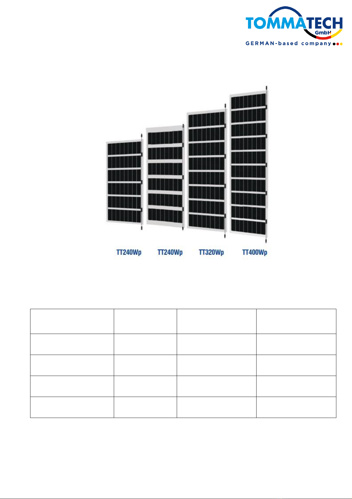
8. APPLICABLE PRODUCTS
This installation manual is prepared for the BIPV solar panels as listed below:
MODULE TYPE
RATED POWER
NUMBER OF CELLS
PANEL DIMENSIONS
TT400-80PMKB12-250
400Wp
80 (10x8)
2500x980x7.6 mm
TT320-64PMKB12-200
320Wp
64 (8x8)
2000x980x7.6 mm
TT240-48PMKB12-175
240Wp
48 (6x8)
1750x980x7.6 mm
TT240-48PMKB12-150
240Wp
48 (16x8)
1500x980x7.6 mm
This manual suits for next models
3
Table of contents
Other TOMMATECH Solar Panel manuals

Popular Solar Panel manuals by other brands

BenQ
BenQ PM245P01 Series installation guide

Tsun
Tsun TSOL-ESK350 Quick installation guide

RED
RED HIGH PERFORMANCE SOLAR COLLECTOR TRANSLATION OF ORIGINAL INSTRUCTIONS

Freeloader
Freeloader SC8100 user manual

Viessmann
Viessmann Vitosol 100-FM SV1F Installation, operating and service instructions

ALZA
ALZA BigBlue B401D manual

Viessmann
Viessmann Vitosol-F Series Installation instructions for contractors

Solar
Solar FLEXI SFP010 user manual

Baxi
Baxi Solarflo installation guide

REC
REC REC235 Series installation manual

Baintech
Baintech BAINTUFF 180W manual

SunMaxx Solar
SunMaxx Solar ThermoPower VHP Series Installation guide & manual


