Leapton LP182*182-M-66-MH-560W Maintenance and service guide

1. Purpose
This manual provides information on installation and safe use of photovoltaic modules produced by
Leapton Energy Co., LTD., and recommends safe and reliable installation instructions and maintenance of
modules for customers.
Before installing the modules, the installer must read and understand this manual. If you have any
questions, please contact the sales or customer service personnel of Leapton for further understanding. When
installing modules, the installer should comply with all safety precautions in this manual and relevant legal
specifications of installation. Installation personnel should be familiar with the mechanical load and electrical
requirements of the installation system. Leapton reserves the right to refuse compensation for any damage
caused by defects in construction or design of the power generation system.
2. scope of application
This document is applicable to the normal installation of single and dual glass solar module in Leapton
Energy Co., LTD.
3. Responsibility
Technology and Craft Department: responsible for documentation, update and maintenance;
4. Related record form
See the document resume
5. Supplementary provision
The final interpretation of this document is the responsibility of the Technology and Craft department. The
document is invalid without a controlled seal. It is forbidden for any department or individual to print, copy or
copy documents without permission. The documents shall be translated from Chinese to English, and the
Chinese content shall prevail in case of any deviation caused by translation.
This document is centrally managed by Leapton Energy (Changshu) Co., LTD.

Contents
1. The basic information
1.1Overview
1.2Warning
2. Installation
2.1Install security
2.2Selection of installation conditions
2.2.1 Selection of installation location
2.2.2 Choice of inclination Angle
2.2.3 Choice of bifacial solar module
2.3Installation Method
2.3.1 Screw installation
2.3.2 Block installation
3. Wiring and connection
4. Maintenance
4.1Visual inspection
4.2Clean
4.3Inspection of connectors and cables
5. Electrical characteristics
6. Disclaimer
7. Modified version and date

1. The basic information
1.1. Overview
First of all, thank you for choosing to use the solar module of Leapton Energy Co., LTD. (hereinafter
referred to as "Leapton"). In order to correctly install and obtain stable power output, please read the
following instructions carefully before installing and maintaining the module. The operation of photovoltaic
power generation system requires relevant professional knowledge. The system must be installed and
maintained by personnel with professional knowledge, and the installation personnel should be familiar
with its mechanical and electrical requirements. If you have any questions, please contact our customer
service department or your local representative.
You are using a power generation product, so to avoid accidents, you need to take appropriate safety
precautions.
Ensure that the current and voltage values generated after the module is connected are within the
applicable range of the current and voltage values of other devices connected to this array and do not
exceed the maximum system voltage that the solar module can bear.
If the modules are installed on a roof, they must be installed on a roof with some fire resistance.
Consult your local building department to decide what roofing materials to use.
Solar modules application class A: hazardous voltage (IEC 61730: higher than 50V DC; EN 61730:
greater than 120V), dangerous power (greater than 240W), module quality meets the safety requirements
according to EN 61730-1 and -2 standards, safety class II.
1.2. Warning
Installation personnel must comply with all safety instructions and precautions mentioned in this
installation manual, and comply with laws or regulations of authorized authorities and other local
requirements. Failure to comply with the relevant safety and installation specifications described in this
manual, or to comply with legal or authorized authority regulations and other local requirements, will result
in the lapse of the limited warranty on purchased module products.
Leapton solar photovoltaic modules have passed the test of the global authority certification body,
please feel free to use in accordance with the requirements and terms of this installation manual.
●Before installing the solar photovoltaic system, please contact the relevant local authority to
determine the installation permit and installation inspection requirements that meet the local
requirements.
●Direct current (DC) is generated when the module battery face is directly exposed to sunlight or
other light sources. Direct contact with the live part of the module may lead to electric shock and
combustion hazard.
●The front glass of the solar module has the function of protecting the module. The damaged solar
module is electrically dangerous (electric shock and fire). Such modules cannot be repaired or repaired and
should be replaced immediately.
●Under ordinary outdoor conditions, the current and voltage generated by the modules are different
from those listed in the parameter sheet. Parameter table is measured under standard test conditions, so in
determining the rated voltage of other modules in the photovoltaic power generation system, cable capacity,
fuse capacity, controller capacity and other parameters related to the power output of the module, refer to
the value of the short-circuit current and open-circuit voltage marked on the module, and design and
installation according to 125% of the value.
●Due to the conditions of photovoltaic power generation is under sunlight, the module can work
normally. Shading has a significant impact on the load generated by the module, and the module should be
completely shielded (e.g., through buildings, chimneys, trees) throughout the year, even partial shading
(e.g., through overhead lines, dirt, snow) should be avoided.
●To reduce the risk of electric shock or combustion, the solar module can be installed with opaque
material on the surface of the module.
●The installation of the module array must be carried out with a solar isolation device and only
qualified professionals can install and maintain the modules.
●If the photovoltaic system uses batteries, and the configuration of module should follow the
opinions of battery manufacturers.
●Do not install modules in areas where flammable gases may be present.
●In the case of power supply is not disconnected, do not use water to extinguish fire.
●Do not move modules by pulling the cables or junction boxes of modules. When moving modules,
two or more people should carry modules with non-slip gloves; Do not carry overhead modules. Do not
move stack modules.
●All modules and systems should be grounded. If there are no special regulations, please follow the
international electrical standards or other international standards.
●Do not stand on or walk on modules as this can damage modules and may pose a risk of personal
injury.
●The modules of the same size and specifications can be connected in series.
●During all transportation, ensure that the vehicle or modules will not be subjected to severe
vibration, as vibration may damage the modules or It causes hidden cracks to the batteries in the modules.
●During all transportation, do not let modules fall to the ground from vehicles, houses, or hands, as
this can cause damage Bad modules or cells in modules.
●Modules (glass, junction box, connector, etc.) should avoid long-term exposure to the environment
containing sulfur, strong acid, strong alkali and other corrosive risks to the product.
●Do not use corrosive chemicals to wipe the modules, do not brush paint or corrosive substances on
the surface of the modules;
●Do not disconnect modules when the load is working.
●Photovoltaic modules use anti-reflective film technology, if the module is observed at different
angles found color difference, this is a normal phenomenon. It is not recommended that coated and
non-coated modules be installed on the same array or roof.
●The connector of the junction box should not be in contact with oily substances, organic solvents
and other corrosive materials to avoid damaging the connector. Such as alcohol, gasoline, lubricant, rust
inhibitor, herbicide and so on.
●Before installation of modules, it is recommended to add rain proof facilities in the storage of the
project site to avoid direct open placement.
●Do not install modules under artificial spotlight.
●Maximum altitude of PV module ≤2000m.
2. Installation
2.1. Install security
●When installing, wear protective head cover, insulating gloves, rubber insulating shoes and other
protective measures.
●In the photovoltaic system installation or maintenance, please do not wear metal rings, watches
and other metal material products, so as not to cause electric shock risk, damage modules.

●When installing, unpack the modules. Once the modules are removed from the packing box, they
should be installed in time and connected to the bus box. If they are not installed immediately, protective
measures should be taken for the connecting head (such as adding rubber joint cover, etc.).
●Do not touch the modules unnecessarily during installation. The surfaces and borders of the
modules may be very hot, which could lead to burns or electric shocks.
●Do not install in rainy, snowy or windy weather conditions.
●Due to the danger of electric shock, do not install the modules if the junction box terminals are wet.
Use dry insulated tools, not wet ones.
●During installation, do not throw any objects (such as modules or tools).
●Please ensure that the installation site is near, there is no or no combustible gas.
●Correctly connect the male and female connectors, check the wiring condition, all the connectors
shall not be separated from the module, and take a certain way so that the connector will not bruise or
squeeze the backplane on the module.
●No matter whether the module is connected to the PHOTOVOLTAIC system or not, do not touch the
junction box or the male or female head with bare hands during installation or when the light is shining on
the module.
●Do not add excessive force or objects on the surface of the module, or distort the frame of the
module.
●Do not put heavy objects or impact on the glass or backplane of the module, which may damage
the battery or cause hidden crack of the battery.
●Do not use sharp tools to clean the glass or back film of the module, as this will leave scratches on
the module.
●Do not drill holes in the frame of the module without authorization.
●For the structure installed on the roof, please try to follow the safety principle of "top to bottom"
and/or "left to right". Please do not stand on the modules, because it will damage the modules and also
cause personal safety hazard.
●Modules will have thermal expansion and cold contraction effect, installation of two adjacent
conventional modules recommended spacing > 10mm; The minimum clearance between two adjacent
double-sided modules is recommended to be > 20mm; If you have special requirements, please confirm
with Beautiful waterfall after installation;
●It is recommended that during installation, disassembly, maintenance and any other related
process, the force between cable and connector, cable and junction box should not be greater than 60N.
2.2. Selection of installation conditions
1) Relative humidity: < 85%
2) Operating ambient temperature between -40℃(-40℉) and +85℃(185℉)
3) Recommended operating temperature range -20°C (-4℉) to +50°C (122℉)
Note: Module mechanical loads (including wind and snow pressures) are based on installation method
and location and must be calculated by professional installers according to system design requirements.
2.2.1. Selection of installation location
In general, solar modules should be installed in areas that receive the most light throughout the year.
In the Northern hemisphere, modules are best placed facing south, while in the southern hemisphere,
modules are best placed facing north. If the module tilts 30 degrees from due south (or due north), it will
lose about 10% to 15% of power output; If the module tilts 60 degrees from due south (or due north), it will
lose approximately 20% to 30% of power output. When selecting locations, avoid trees, buildings, or other
obstacles that cast shadows on modules. Although the manufacturer has installed appropriate bypass
diodes to minimize this loss, the shadow still causes a reduction in output power.
When the photovoltaic power generation system uses the battery, the battery must be installed
correctly, which can protect the operation of the system and ensure the safe use of users; Please follow the
battery manufacturer's instructions for installation, operation and maintenance; In general, batteries (or
batteries) should be kept away from major traffic routes for people and animals; In addition to the normal
operation of batteries, avoid direct sunlight, rain and snow erosion, and maintain good ventilation. Most
batteries produce hydrogen when they are charged, which can easily explode. Be sure not to light an open
flame or create sparks around the battery. If the battery is installed outdoors, it must be placed in a specially
designed place with good insulation and ventilation.
Do not install modules near open flames or flammable materials.
Do not install modules where they will be soaked in water or continuously exposed to water wheels or
fountains.
2.2.2. Choice of inclination Angle
Fixed the recommended installation Angle during system installation
Latitude of the installation site
Installation Angle
0°~15°
15°
15°~25°
The latitude of the installation site is the same
25°~30°
Latitude of the installation site +5°
30°~35°
Latitude of the installation site +10°
35°~40°
Latitude of the installation site +15°
40°+
Latitude of the installation site +20°
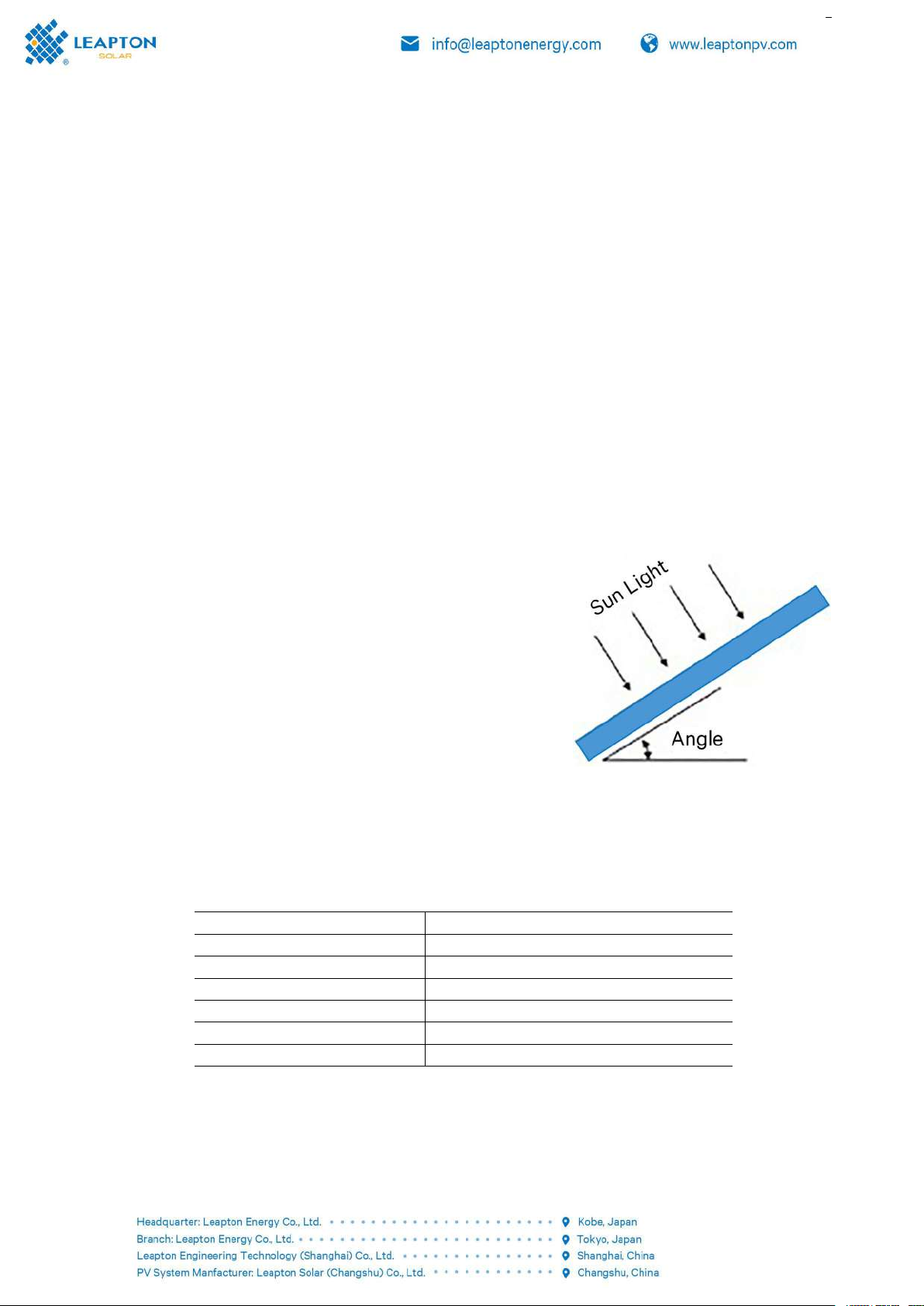
The tilt Angle of the solar module refers to the Angle
between the surface of the module and the ground plane (as
shown in Figure 1 on the right). The power output is maximum
when the module is directly facing the sun.
If connected to an independent PHOTOVOLTAIC system, the
module should be installed at an Angle that maximizes the
power output according to the season and light conditions.
Generally speaking, if the output of the module can be satisfied
with the lowest light intensity during the year, then the output
of the module at this Angle can meet the needs of the whole
year. For grid-connected systems, the installation Angle of
modules should be selected based on the basic principle of
maximizing annual output.

2.2.3. Choice of bifacial solar module
Under certain installation conditions, the bifacial (double-glass/transparent) modules will also generate
power when the reflected light is received on the back side, giving the power station system additional
generation gain.
Modules should be completely sheltered (e.g., through buildings, chimneys, trees) throughout the year,
even partial (shadow) shielding (e.g., through overhead lines, dirt, snow, back supports) should be avoided.
The yield gain is related to ground reflectivity, module height, array spacing, and rear shadow
occlusion.
In general, different ground reflectivity is different, resulting in different module generation gain. As
shown in the table.
The reflectivity of different surfaces
Ground Type
Water
Grass
Land
Concrete
Sand
Snow
Reflectivity range(%)
5-12
12-25
20-33
20-40
20-40
80-85
Different ground height also affects the gain of power generation of the Bifacial solar module. You are
advised to install the bifacial solar module at a height of 1 to 2 meters. As shown in the figure.
Schematic diagram of installing bifacial solar module off the ground
During system design, in addition to the ground type and ground height, proper array spacing and how
to avoid shadowing on the back need to be considered. Please consult professional system designers.
2.3. Installation Method
Modules can be installed in the following ways: screw mounting and block mounting.
Note:
1) All installation methods introduced here are for reference only, Leapton is not responsible for
providing relevant installation modules, module system design, installation. Mechanical loading and safety
must be done by a professional system installer or experienced person.
2) Before installation, the following important items need to be confirmed:
A) Before installation, check the appearance for defects or other sundries and the safety performance
of the junction box, if any, remove it.
B) Check whether the serial number of the module is correct.
3) The maximum pressure that the front side of The Leapton solar module can bear is 5400Pa (only for
the module models involved in this manual), and the back side is 2400Pa. The maximum design pressure
that the front side can withstand is 3600Pa and the back side is 1600Pa. The safety factor is 1.5. If the
environment for installing modules is snowy or windy, take special protection measures to meet actual
requirements.
2.3.1. Screw installation
There are mounting holes for connecting with the bracket system on the rear frame of the photovoltaic
module, including φ9x14 mounting hole and φ7x10 mounting hole. When using φ9x14 mounting holes,
please use M8 bolt set in the table; when using φ7x10 mounting holes, please use M6 bolt set in the table.
Mounting fasteners
M8 bolt kit
M6 bolt kit
Note
Bolt
M8
M6
Use corrosion
resistant fasteners
Sus304 is
recommended
Flat washer
2*8
2*6
Elastic washer
8
6
Nut
M8
M6
The torque range
16N·m-20N·m
14N·m-18N·m
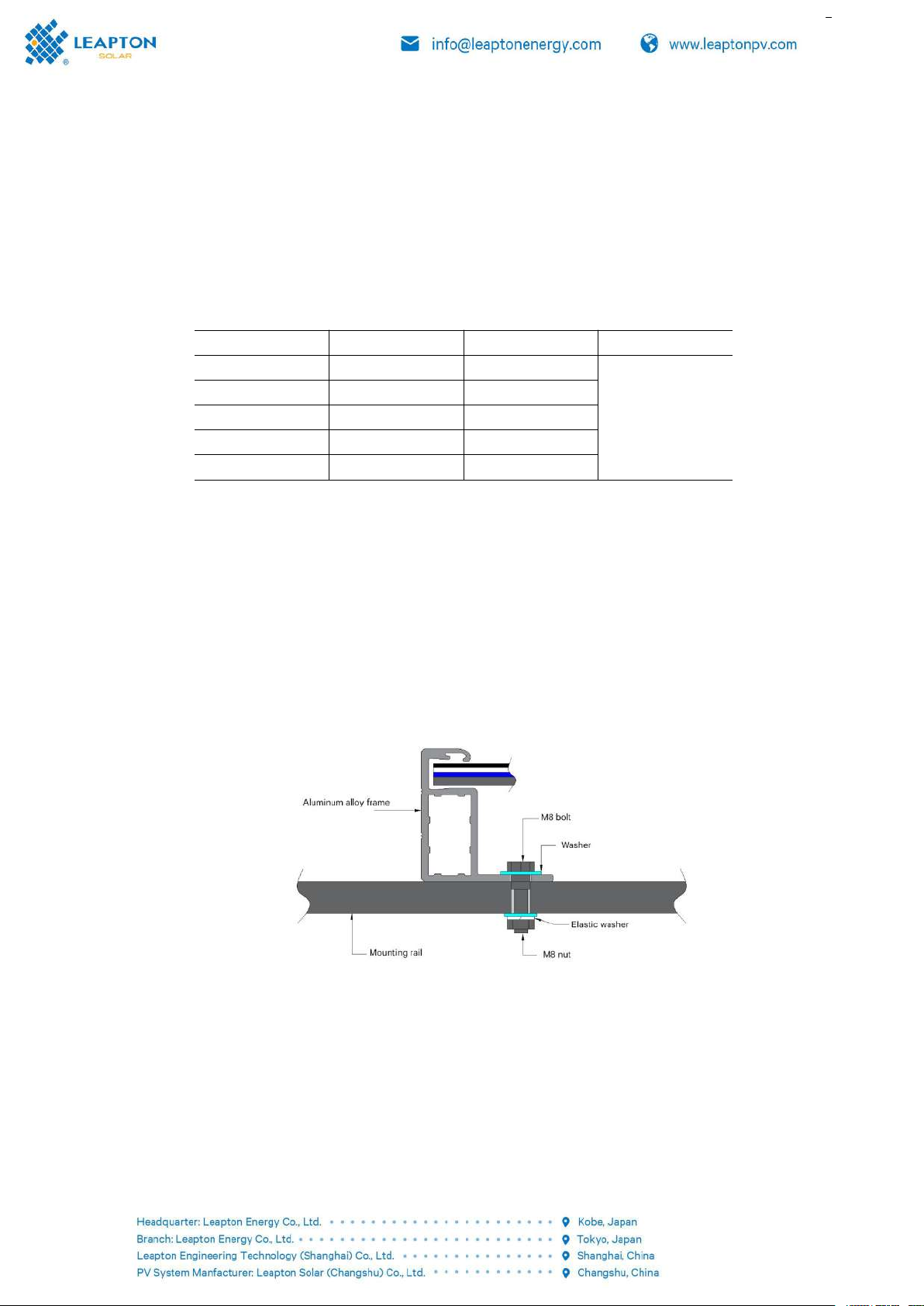
The frame of a single solar module has eight mounting holes of 9mm x 14mm. To ensure the fastness
of the solar module after installation, all eight mounting holes must be used. Install the solar module on the
guide rail with M8 anti-corrosion screws, elastic washers and flat washers, and the torque used should be
large enough to allow the module to be properly fixed. The reference torque of M8 screw ranges from 16
N·m to 20N·m. If a special support system or installation method is required, please reconfirm the torque
value with the support supplier. For detailed installation information, see Figure 3 below
Screw installation method of the module type with 8 mounting holes and installation position in Figure
4 and table
Screw installation method of the module type with 4 mounting holes and installation position in Figure
5 and table
Figure 3: Screw installation diagram
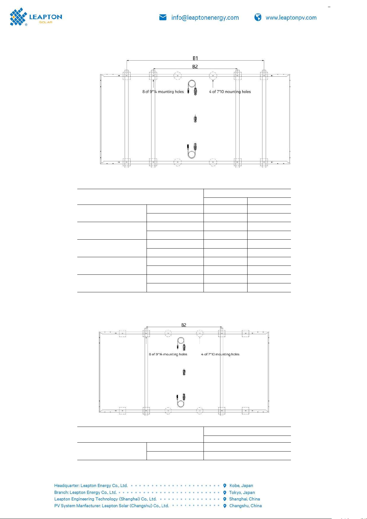
2.3.1.1. Screw installation(8 mounting holes - use inner 4 + outer 4 mounting holes)
Figure 4: Screw fixing method(8 mounting holes - use inner 4 + outer 4 Installation)
Module Type/Dimension
Load:3600Pa(front)/1600Pa(back)
B1
B2
LP210*210-M-66-MH-xxxW
2384*1303*35(mm)
1528
1118
2408*1303*35(mm)
1552
1142
LP210*210-M-55-MH-xxxW
2384*1096*35(mm)
1528
1118
2408*1096*35(mm)
1552
1142
LP210*210-M-66-MB-xxxW
2384*1303*35(mm)
1400
1080
2408*1303*35(mm)
1424
1104
LP210*210-M-55-MB-xxxW
2384*1096*30(mm)
1400
1080
2408*1096*30(mm)
1424
1104
LP182*182-M-78-MH-xxxW
2443*1134*35(mm)
1587
1177
2472*1134*35(mm)
1616
1206
2.3.1.2. Screw installation(8 mounting holes - use inner 4 mounting holes)
Figure 5: Screw fixing method(8 mounting holes – inner 4 Installation)
Module Type/Dimension
Load:3600Pa(front)/1600Pa(back)
B2
LP182*182-M-72-MH-xxxW
2256*1134*35/30(mm)
990
2279*1134*35/30(mm)
1013

2.3.1.3. Screw installation(8 mounting holes - use outer 4 mounting holes)
Figure 6: Screw fixing method(8 mounting holes – outer 4 Installation)
Module Type/Dimension
Load:3600Pa(front)/1600Pa(back)
B1
LP210*210-M-60-MH-xxxW
2172*1303*35(mm)
1316
2195*1303*35(mm)
1339
LP210*210-M-54-MH-xxxW
1962*1303*35(mm)
1154
1980*1303*35(mm)
1172
LP210*210-M-60-MB-xxxW
2172*1303*35(mm)
1188
2195*1303*35(mm)
1211
LP210*210-M-54-MB-xxxW
1962*1303*35(mm)
1154
1980*1303*35(mm)
1172
LP210*210-M-50-MB-xxxW
2172*1096*30(mm)
1188
2195*1096*30(mm)
1211
LP210*210-M-45-MB-xxxW
1962*1096*30(mm)
1154
1980*1096*30(mm)
1172
LP182*182-M-72-MB-xxxW
2256*1134*30(mm)
1272
2279*1134*30(mm)
1295
2.3.1.4. Screw installation (4 mounting holes)
Figure 7: Screw fixing method(4 mounting holes)
Module Type/Dimension
Load:3600Pa(front)/1600Pa(back)
B1
LP210*210-M-48-MH-xxxW
1754*1303*35(mm)
946
1767*1303*35(mm)
959
LP210*210-M-42-MH-xxxW
1540*1303*35(mm)
732
15541303*35(mm)
746
LP210*210-M-50-MH-xxxW
2172*1096*30(mm)
1364
2195*1096*30(mm)
1387
LP210*210-M-45-MH-xxxW
1962*1096*30(mm)
1154
1980*1096*30(mm)
1172
LP210*210-M-40-MH-xxxW
1754*1096*30(mm)
946
1767*1096*30(mm)
959
LP210*210-M-48-MB-xxxW
1754*1303*35(mm)
946
1767*1303*35(mm)
959
LP210*210-M-42-MB-xxxW
1540*1303*35(mm)
732
1554*1303*35(mm)
746
LP210*210-M-40-MB-xxxW
1754*1096*30(mm)
946
1767*1096*30(mm)
959
LP182*182-M-66-MH-xxxW
2073*1134*30(mm)
1265
2094*1134*30(mm)
1286
LP182*182-M-60-MH-xxxW
1890*1134*30(mm)
1082
1909*1134*30(mm)
1101
LP182*182-M-54-MH-xxxW
1707*1134*30(mm)
899
1724*1134*30(mm)
916
LP182*182-M-60-MB-xxxW
1890*1134*30(mm)
1082
1909*1134*30(mm)
1101
LP182*182-M-54-MB-xxxW
1707*1134*30(mm)
899
1724*1134*30(mm)
916
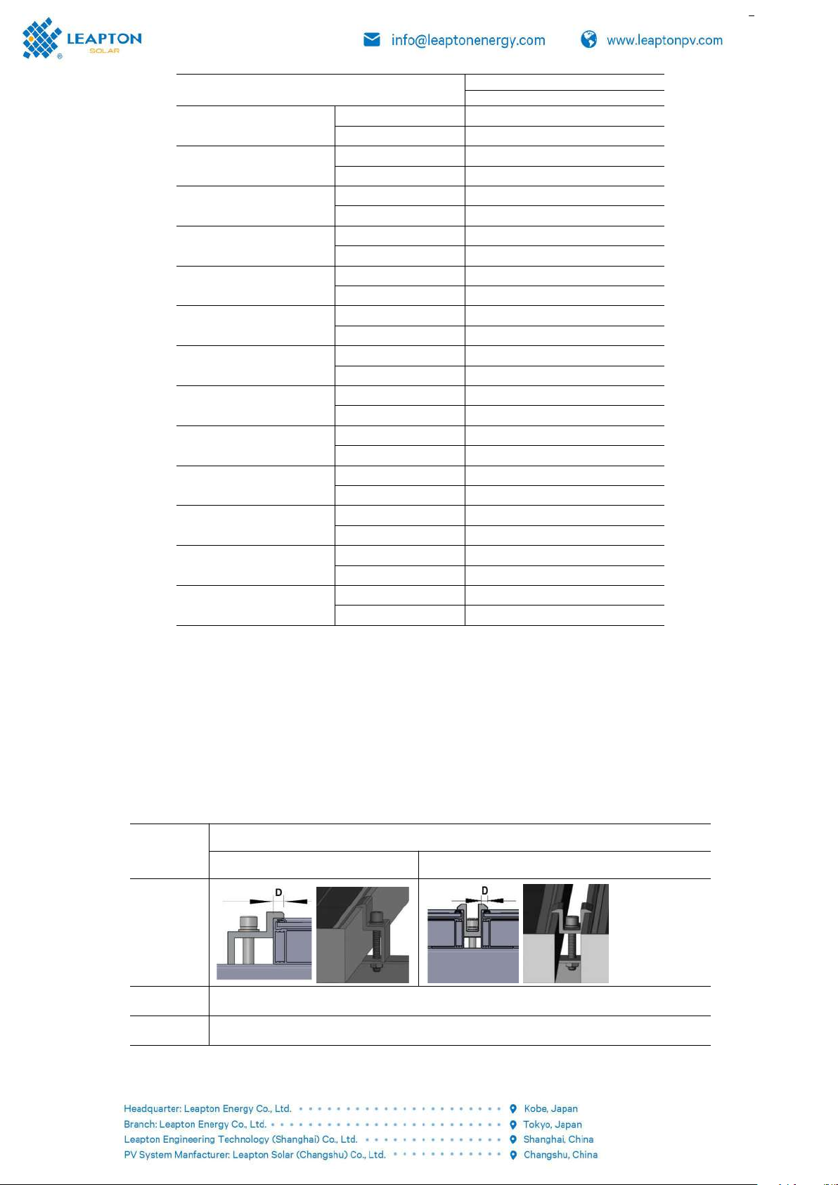
2.3.2. Clamp installation
The clamp used should not contact the glass or deform the frame to ensure that the clamp does not
create shadows on the glass. Under no circumstances should the frame be modified; When selecting the
clamp installation method, make sure there are at least 4 clamps on each solar module. The number of
clamps to be used depends on the strength of the local wind and snow pressure. If the pressure is greater
than expected, additional clamps or supports are required to ensure that the solar module can withstand
the pressure. The torque used during installation should be large enough to allow the solar module to hold
well (details check with the clamp or mounting supplier).
Clamp Type
Clamp Picture
Side clamp
Middle clamp
For mounting
clampls of
aluminum
frame solar
modules
Note
Ensure that the clamp touches 7mm≤D≤10mm on side A of the solar module
Clamp Spec
Clamp Dimension:Length L≥50mm,Thickness ≥3mm (For aluminum frame)
Fasteners
M8 bolts, nuts, spring washers, flat washers, clamps (Corrosion resistant firmware is recommended to maximize
support life)
Figure 8 & table: 210mm cells solar module installation position and module type with 4 clamps in long
side
Figure 9 & table: 210mm cells solar module installation position and
module type with 8 clamps in long side
Figure 10 & table: 182mm cells solar module installation position and
module type with 4 clamps in long side
Figure 11 & table: 182mm cells solar module installation position and
module type with 8 clamps in long side
Figure 12 & table: 182mm cells solar module installation position and module type with 4 clamps in top
mounting of long side
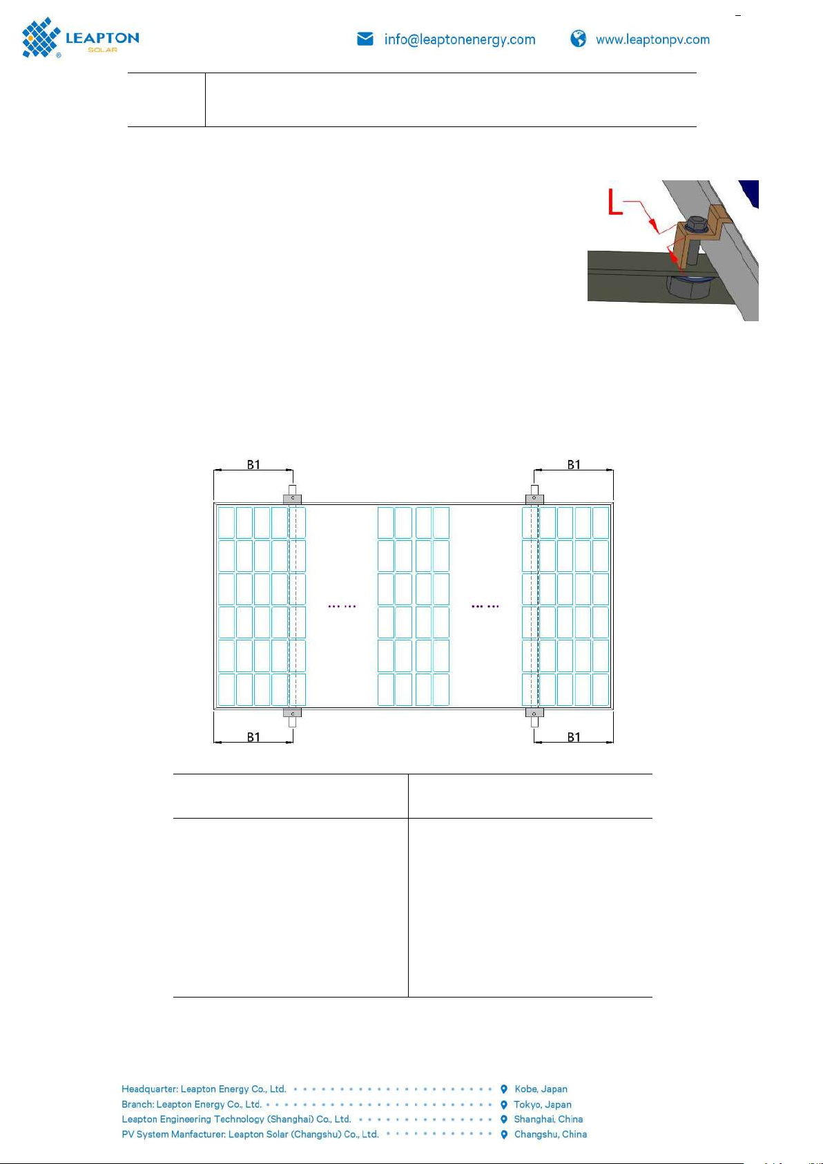
2.3.2.1. Clamps installation in long side(4 clamps)-210mm cells
Figure 9: clamps fixed method in long side
Module Type
Maximum test load:3600Pa (front)/1600Pa(back)
LP210*210-M-40-MH-xxxW、
LP210*210-M-42-MH-xxxW、
LP210*210-M-45-MH-xxxW、
LP210*210-M-48-MH-xxxW、
LP210*210-M-50-MH-xxxW、
LP210*210-M-54-MH-xxxW、
LP210*210-M-55-MH-xxxW、
LP210*210-M-60-MH-xxxW
B1=350mm~450mm
LP210*210-M-55-MB-xxxW、
LP210*210-M-60-MB-xxxW
LP210*210-M-66-MH-xxxW
B1=440mm~540mm
LP210*210-M-40-MB-xxxW、
LP210*210-M-42-MB-xxxW、
LP210*210-M-45-MB-xxxW、
LP210*210-M-48-MB-xxxW、
LP210*210-M-50-MB-xxxW、
LP210*210-M-54-MB-xxxW、
LP210*210-M-60-MB-xxxW
B1=350mm~450mm
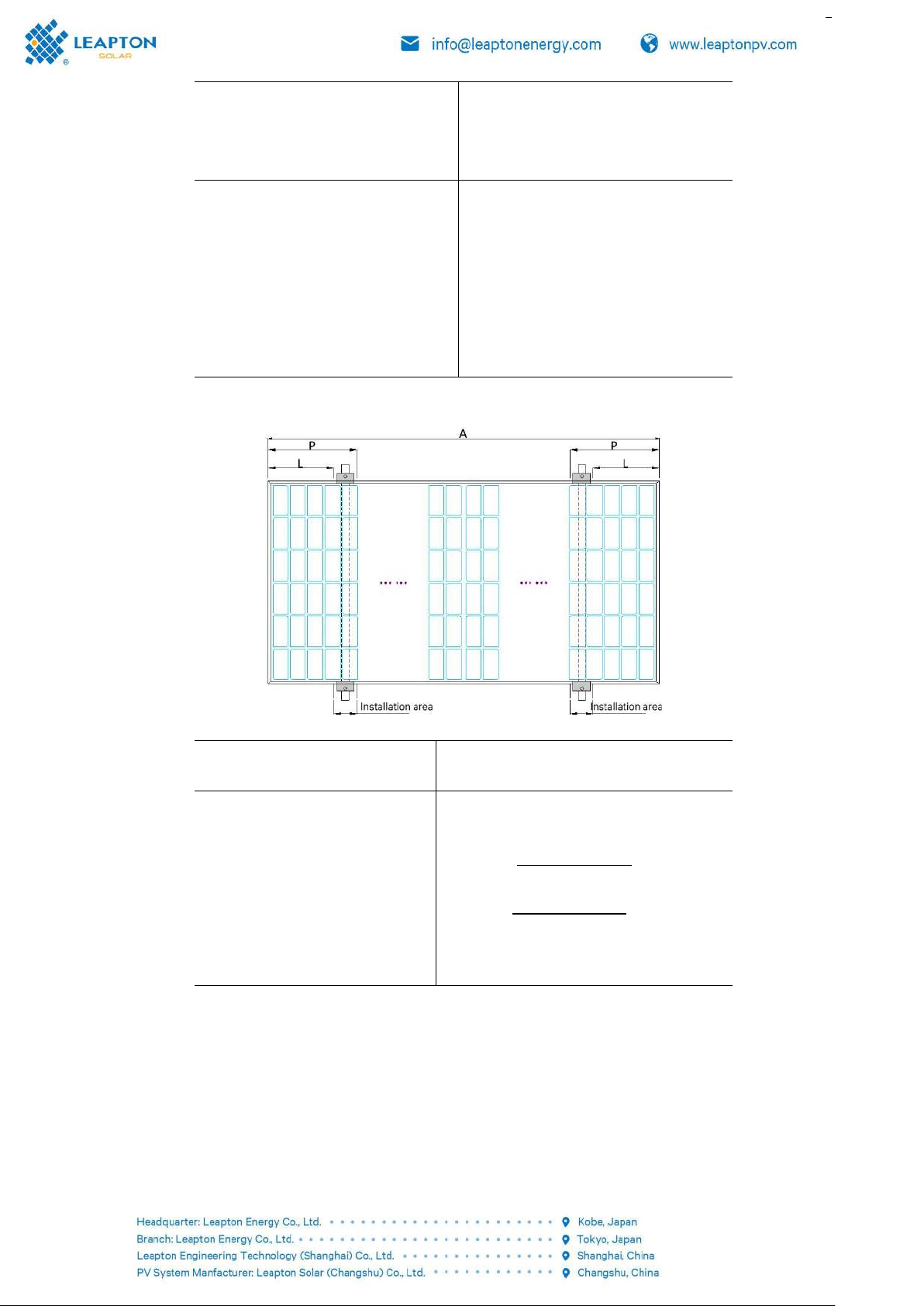
2.3.2.2. Clamps installation in long side(4 clamps)- 182mm cells
Figure 10: clamps fixed method in long side
Module Type
Maximum test load:3600Pa (front)/1600Pa(back)
LP182*182-M-54-MH-xxxW 、
LP182*182-M-60-MH-xxxW 、
LP182*182-M-66-MH-xxxW 、
LP182*182-M-72-MH-xxxW 、
LP182*182-M-54-MB-xxxW 、
LP182*182-M-60-MB-xxxW 、
LP182*182-M-66-MB-xxxW 、
LP182*182-M-72-MB-xxxW
L
-50(mm)
P=
+50(mm)

2.3.2.3. Clampsinstallation inlongside(8clamps)-182mm cells
F i g u r e 1 1 : c l a m p s fixedmethodi n l o n g s i d e
Module T y p e
Maximum t e s t load:3600Pa (front)/1600Pa(back)
LP182*182-M-78-MH-xxxW 、
LP182*182-M-78-MB-xxxW
A 1 = 4 0 0 m m
A2=400mm
2.3.2.4. Clampsinstallation int o p mounting oflongside(4clamps)-182mm cells
Module T y p e
Maximum t e s t l o a d : 2 4 00Pa( f r o n t ) / 1000Pa(back)
Safetyfactor:1.0
LP182*182-M-54-MH-xxxW 、
LP182*182-M-60-MH-xxxW 、
LP182*182-M-54-MB-xxxW 、
LP182*182-M-60-MB-xxxW 、
LP210*210-M-40-MB-xxxW 、
LP210*210-M-40-MH-xxxW
L=20mm~50mm

3. Connection
A) Please read the operation manual of solar system carefully before installation, and use multi-port
connection cable series or parallel solar modules according to user's requirements for system power,
current and voltage.
B) In series, solar modules with the same current should be selected for connection. The total voltage
generated by the modules in series should not be higher than the maximum voltage allowed by the system.
The maximum number of modules in series depends on the system design, inverter type and surrounding
conditions.
C) Mark the maximum rated current value in the solar module array. The rated current also
corresponds to the maximum reverse current that a solar module can withstand on the product nameplate
or product specifications. For example, when one string is shaded, the other two will form a load leading
current loop. According to the maximum rated fuse current of the solar module and the local electrical
installation standard, suitable fuses should be provided for the connection of the parallel series of the solar
module for circuit protection.
D) According to the installation instructions of the PV control system, turn on the connectors of the
control system and connect the PV array cables to the connectors. The cross-sectional area and capacity of
the cable must be equal to the maximum short-circuit current of the PV array (for a single solar module,
the cross-sectional area of the cable is 4mm2-6 mm2, otherwise the cable and connector will overheat).
Please note that the cable temperature limit is 85.
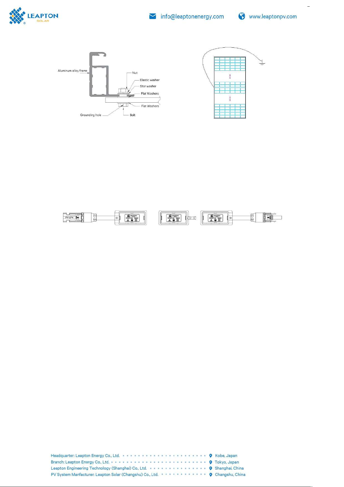
E) Ensure that all aluminum alloy frames and brackets of solar modules are grounded in accordance
with international or local electrical regulations; Use the reserved holes to connect the hardware to the
ground. Use a stainless steel star washer (see Figure 13-1 or 13-2 in Figure 13-1) between the ground cable
and the frame of the solar module. The washer is used to prevent corrosion caused by contact with metals
of different attributes, and tighten screws. The following figure shows the fixed grounding scheme. You can
choose a grounding scheme based on the solar module installation vendor's suggestions.
Reference Scheme 1
solar modules
Shown
Connection method
Place the star ring, flat washer,
and ground cable in sequence,
screw through the ground hole,
and tighten it to secure adjacent
solar modules.
Leapton recommended that the
grounding resistance <1 ohm
Figure 13-1:Grounding diagram
Reference Scheme 2
Figure 13-2:Grounding diagram
F) Electrical connections shall comply with the relevant electrical regulations of the installation site.
G) The assembly is equipped with by-pass diodes, which may damage the diodes, cables and junction
boxes if improperly installed.
H) Define the length of the junction box cables as (different installation methods correspond to
different cable lengths for different solar module types), or as required by customers on the length of the
cable. As shown in Figure 14 below, please consider the length of the lead wire before designing the cable.
It is not recommended to plug different types of connectors.
Figure 14:Half cells/Transparent backsheet solar module junction box
I) For Non-PID resistant solar modules, the project system design recommends the negative grounding
installation of the inverter to avoid PID effect.
J) If the solar modules are in series, the total voltage is equal to the sum of the voltages of the
individual solar modules. Recommendations are as follows:
System voltage ≥N * Voc* [1 + TCVoc * (Tmin-25)]
* * note:
N: serial number of single solar module
Voc: Open circuit voltage (refer to product label or datasheet)
TCVoc: Open circuit voltage temperature coefficient (refer to product label or datasheet)
Tmin: Minimum ambient temperature
K) For water projects, it is recommended to adopt negative grounding installation of inverter to avoid
PID effect in project system design.
4. Maintenance
Solar modules need to be inspected and maintained regularly, especially during the warranty period. In
order to ensure that the solar modules can achieve the best performance, Leapton recommends the
following maintenance measures:
4.1. appearance inspection
Check the solar modules carefully for appearance defects. Focus on the following points:

A) Photovoltaic modules use anti-reflective film technology. It is normal to find color differences when
observed at different angles
B) Whether the solar module glass is damaged;
C) Whether sharp objects touch the surface of the solar module;
D) Whether the solar module is blocked by obstacles and foreign bodies;
E) Whether there is corrosion near the grid line of the cells. This corrosion is caused by water vapor
penetrating into the interior of the solar modules caused by the damage of the surface packaging materials
during installation or transportation.
F) Observe whether the backside of the solar module is burned out;
G) Check whether the fixing screws between solar modules and mounting are loose or damaged, and
timely adjust or repair them.
4.2. Clean
A) The accumulation of dust or dirt on the surface of the solar modules can reduce the power output.
If possible, perform regular cleaning once a year (depending on the conditions at the installation site).
Clean with a soft cloth, dry or damp. It is not recommended to use water containing minerals for cleaning,
so as not to leave dirt on the glass surface; It is recommended to use neutral water to clean the glass, avoid
strong acid and alkali, so as not to damage the glass coating layer;
B) Under no circumstances shall solar modules be cleaned with rough surface materials;
C) In order to reduce potential electric shocks or burns, Leapton recommends cleaning photovoltaic
modules in the early morning or evening when the light is not strong and the module temperature is low,
especially in areas with high temperatures;
D) Do not attempt to clean PV modules with features such as broken glass or exposed wires, which
would be at risk of electric shock.
4.3. Connector and Cable inspection
It is recommended to perform the following preventive maintenance every six months:
A) Check the sealant of the junction box to ensure that there are no cracks or gaps;
B) Check the aging signs of photovoltaic modules. This includes possible rodent damage, climate aging,
and whether all connectors are tightly connected and corroded. Check that the solar modules are properly
grounded.
5. Electrical characteristics
The electrical performance parameters of the solar modules were measured under standard test
conditions of 1000W/m2light intensity, AM1.5, and ambient temperature of 25℃(77℉) with power
tolerances of ±3% and open circuit voltage and short circuit current tolerances of ±5%. In some cases, the
solar module may generate a higher or lower voltage or current than the rated.
Corresponding electrical performance parameters can be downloaded from the website:
www.leaptonpv.com
6. Disclaimers
As the use of this manual and the conditions for the installation, operation, use and maintenance of
the solar modules are beyond the control of Leapton, Leapton shall not be liable for any loss, damage or
expense arising from the installation, operation, use or maintenance.

Leapton assumes no responsibility for any infringement of patents or third party rights that may result
from the use of the solar module products. Customer does not obtain any patent or license to use any
patent rights, whether express or implied, by virtue of the use of Leapton products.
The information in this manual is based on the knowledge and experience of Leapton which is believed
to be reliable, but the information and related recommendations, including but not limited to the above
product specifications, do not constitute any warranty, express or implied. Leapton reserves the right to
modify the manual, PV products, specifications or product information without prior notice.
Appendix: Application products
This document applies to the following series of Leapton products:
Series
Type
Power Range
182 normal/grid
156 cell:LP182*182-M-78-MH-xxxW
xxx=560-605, in increment of 5
144 cell:LP182*182-M-72-MH-xxxW
xxx=515-570, in increment of 5
132 cell:LP182*182-M-66-MH-xxxW
xxx=475-520, in increment of 5
120 cell:LP182*182-M-60-MH-xxxW
xxx=430-475, in increment of 5
108 cell:LP182*182-M-54-MH-xxxW
xxx=390-425, in increment of 5
182 dual glass
156 cell:LP182*182-M-78-MB-xxxW
xxx=560-605, in increment of 5
144 cell:LP182*182-M-72-MB-xxxW
xxx=515-555, in increment of 5
132 cell:LP182*182-M-66-MB-xxxW
xxx=475-510, in increment of 5
120 cell:LP182*182-M-60-MB-xxxW
xxx=430-465, in increment of 5
108 cell:LP182*182-M-54-MB-xxxW
xxx=390-415, in increment of 5
210 normal/grid
132 cell:LP210*210-M-66-MH-xxxW
xxx=630-670, in increment of 5
120 cell:LP210*210-M-60-MH-xxxW
xxx=575-610, in increment of 5
108 cell:LP210*210-M-54-MH-xxxW
xxx=515-545, in increment of 5
96 cell:LP210*210-M-48-MH-xxxW
xxx=460-485, in increment of 5
84 cell:LP210*210-M-42-MH-xxxW
xxx=400-425, in increment of 5
110 cell:LP210*210-M-55-MH-xxxW
xxx=520-555, in increment of 5
100 cell:LP210*210-M-50-MH-xxxW
xxx=475-505, in increment of 5
90 cell:LP210*210-M-45-MH-xxxW
xxx=425-455, in increment of 5
80 cell:LP210*210-M-45-MH-xxxW
xxx=380-400, in increment of 5
210 dual glass
132 cell:LP210*210-M-66-MB-xxxW
xxx=630-670, in increment of 5
120 cell:LP210*210-M-60-MB-xxxW
xxx=575-610, in increment of 5
108 cell:LP210*210-M-54-MB-xxxW
xxx=515-545, in increment of 5
96 cell:LP210*210-M-48-MB-xxxW
xxx=460-485, in increment of 5
84 cell:LP210*210-M-42-MB-xxxW
xxx=400-425, in increment of 5
110 cell:LP210*210-M-55-MB-xxxW
xxx=520-555, in increment of 5
100 cell:LP210*210-M-50-MB-xxxW
xxx=475-505, in increment of 5
90 cell:LP210*210-M-45-MB-xxxW
xxx=425-455, in increment of 5
80 cell:LP210*210-M-45-MB-xxxW
xxx=380-400, in increment of 5
7. Modify the version and date
Document number: LP-QD-JS-021 Version number: A0 Issued in September 2022
This manual suits for next models
216
Table of contents


