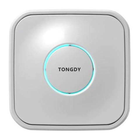
Tongdy PMD-18 Series User manual

1/ 16
Instruction for PMD-In Duct Air Quality Detector
V.1912
PMD In-Duct Air Quality Detector
—Commercial Grade Detector
Please read this instrument carefully before installing and using the device. The instruction includes
installation of PMD-18XX all models. Some content if PMD in your hand is not involved, please
ignore.
Check Accessories
Unpack the box and examine PMD and the accessories as below list.
1. Instruction manual –1 piece
2. PMD In-Duct air quality detector –1 unit
3. The pitot tube of PMD –1 piece
4. Waterproof connector –1 piece
5. Pipeline seal ring -1 piece
6. PMD assembly screw 2pcs and duct
mounting screw –2pcs
7. Hexagonal screwdriver –1 piece
8. Filter –1 piece
9. 220V power cable –1 piece (optional) or
24V power adaptor (optional) –1 set
Installation Requirements (IMPORTANT!)
1. Install in the air supply duct. Then install the PMD on the main air duct where is far from the fresh
fan machine or close to the branch duct.
2. Install in the return air duct. Then Install the PMD on the main air duct close to the return air fan,
or more than 1 meter from the return air outlet.
3. Installation of pitot tube should be accordance with the direction of the wind, please see P4
“Installation”.
4. The installation location should fully consider the requirement of convenient regular
maintenance.
5. PMD has two power supply selection,24VAC/VDC or 110-230VAC power supply. Please note
the power part must be waterproof and safe.
6. Note that the S/N number on the pitot tube must be mated with the PMD device with the same
s/n number. The two parts make up a whole device. Its temperature and humidity is calibrated
for the whole device. Therefore, each pitot tube must be matched with its own main unit. Do not
mix them up.
7. When disassembling and assembling the pitot tube, power must be cut off and no live operation
is allowed. The pitot tube must be assembled and tightened on the device.
Main unit
T&RH sensor
Pitot tube
Main unit

2/ 16
Instruction for PMD-In Duct Air Quality Detector
V.1912
8. For MSD/PMD-18XXD, It is installed in a place not touched by users. The insulation
requirements for external secondary wired communication terminals and exposed secondary
circuits will be evaluated on the final connection system. It is inaccessible to users during power
on.
Dimensions and Wiring Diagram
Host size: 180mm(Height) X125mm (Width) X 65.50mm (Thickness)
Pitot tube size: Total length: 279.5mm / Insertion pipe length: 235mm /Opening diameter: Ф35mm
Flange mounting hole distance: 77.5mm
Net weight: 1000g
PMD-181XD wiring diagram (two sets of terminals, power supply wiring on the left, RS485 wiring on
the right, do not connect wrong!).
PMD-183X Insert the RJ45 crystal head into the RJ45 socket on the bottom of the PMD as shown
below and make sure it is secure.
Tongdy Sensing Technology

3/ 16
Instruction for PMD-In Duct Air Quality Detector
V.1912
Assembly of Main unit and Pitot Tube
STEP 1: See the mark of the main unit, as shown in
the figure below, REMOVE is the direction in which
the pitot tube is removed, and FIX is in the fixed
direction. The pitot tube must be matched with the
original main unit with the same s/n no.
STEP 2: The pitot tube is docked with the main unit. Their series numbers are the same, don’t mess
up.
As shown in the figure below, install the side of the pitot
tube marked with the Windward Side facing down, and
align it with the rear
mounting hole of the main
unit.
Tongdy Sensing Technology

4/ 16
Instruction for PMD-In Duct Air Quality Detector
V.1912
STEP 3: After the pitot tube is inserted into the main unit assembly hole, the alignment mark
horizontal line is rotated 90 degrees clockwise.
Installation
1. For the wind flow is from right to left (ie "right", factory default)
STEP 1: Confirm the installation position, and open a hole of 35mm diameter with the hole opener
on the air duct. Insert the pitot tube into the air duct.(Note: the side of the pitot tube marked with the
Windward Side face to the airflow direction)
STEP 2: Insert the pitot tube and screw it to the outside of the air duct.

5/ 16
Instruction for PMD-In Duct Air Quality Detector
V.1912
STEP 3: Install the main unit. Connect the main unit horizontally (Tongdy logo is on the left) with the
pitot tube interface (as shown in the left figure), and then rotate it 90 degrees clockwise
fixed. (right figure). Complete installation.
2. The direction of the wind's airflow is opposite to the above, that is, the wind flow is from
left to right (ie "left").
Note: If the end user predetermines the installation location and direction, please inform the
Manufacturer, so that below STEP1~STEP8 can be pre-completed in the factory.
STEP 1: Unscrew the four assembly screws and open the upper casing part of the main unit.
STEP 2: See the black MSM sensor module. Pull out the air inlet filter (as the left figure) pressed to
the lower right side of the MSM module, and then remove the fixing screws on the middle of the
module (as the right figure)

6/ 16
Instruction for PMD-In Duct Air Quality Detector
V.1912
STEP 3: Remove the MSM module from the sealed compartment and rotate the module 180
degrees (left figure), and replace the MSM module (right figure) with the original position.
STEP 4: Fix the MSM module and insert the air inlet filter into the upper left slot of the MSM module.
STEP 5: Put the sealing compartment casing back
and fix it.
STEP 6: Install the pitot tube. Confirm the installation position and open a hole of a 35mm diameter
with the hole opener on the air duct. Insert the pitot tube into the air duct.
(Note that the side of the pitot tube marked with Windward Side face to the airflow direction)

7/ 16
Instruction for PMD-In Duct Air Quality Detector
V.1912
STEP 7: Insert the pitot tube and fix it with screws.
STEP 8: Assemble the main unit. Insert the main unit laterally into the air duct's counter interface
(left figure) and then rotate it 90 degrees clockwise (right figure). The installation is completed.
3. PMD18-181X RS485 Wiring:
STEP 1: Open the casing of the electrical wiring
part of the main unit.

8/ 16
Instruction for PMD-In Duct Air Quality Detector
V.1912
STEP 2: Remove the two sets of terminals
for power supply and RS485 respectively
Special Note:
The left terminal is the power terminal block. The right
terminal is the RS485 terminal block. Don't get it
wrong!
STEP 3: Go through the power cable and RS485 cable
from each waterproof connector respectively.
STEP 4: Press the cable on the terminal blocks.
STEP 5: Plug the terminals of the wired cable back into the pin
position of the power supply board and lock the inlet of the
waterproof connector.

9/ 16
Instruction for PMD-In Duct Air Quality Detector
V.1912
STEP 6: Fasten the casing of the electrical wiring part and install the original screws.
Regular Maintenance:
In order to ensure the accuracy of the PMD data, the end users need to perform regular
maintenance on the equipment under typical environment. The maintenance period of the general
project is 3, 6, and 12 months, and the special environment should shorten the maintenance period.
The main maintenance should include: internal cleaning of the outer casing, internal structure
cleaning, air inlet filter cleaning, and module cleaning.
1. Cleaning of the inlet filter: The general maintenance period is up to 3 months, and the special
environment should shorten the maintenance period, especially in the environment where the return
air duct is dusty.
2. Cleaning of internal structure: The general maintenance period is up to 12 months, and the
special environment should shorten the maintenance period.
3. Sensing module cleaning: The general maintenance period is up to 12 months, and the special
environment should shorten the maintenance period.
STEP 1: Open the upper casing of the main unit.
STEP 2: Remove the dust filter next to the air inlet of the black MSM sensor module, clean the filter.

10 / 16
Instruction for PMD-In Duct Air Quality Detector
V.1912
STEP 3: Remove the mounting screw on the middle of the MSM module, take out the module, and
clean the module inlet and outlet with the air pump to clean the module inside.
STEP 4:Assembling the MSM module after cleaning.
Indicators, buttons and external windows:
(The bottom right side of the PMD is the wiring and indicator area).
1. GPRS RJ45 CONFIG: GPRS or RJ45 configuration
red indicator and button,(Optional by model) Located in the upper left
corner.
For details, see the GPRS or RJ45 communication configuration file.
Indicator

11 / 16
Instruction for PMD-In Duct Air Quality Detector
V.1912
2. WIFI CONFIG: WIFI configuration button(optional by model),
located in the middle of the left side. Use with the "WIFI" indicator in
the lower right corner. For details, see the WIFI communication
configuration file. The series of WIFI communication, the default is
MQTT protocol, the data is uploaded to the Mytongdy platform.
Tip: If the customer needs other protocol and platforms, please
contact the sales for pre-sales consultation.
3. SCALE: three-color concentration indicator, the default is the
average concentration change of PM2.5 every 1 minute.
PM2.5 <35ug/m3 green light on, 35~75ug/m3 yellow light
on, >75ug/m3 red light on.
This indicator can be controlled by RS485 communication command to be controlled by any one of
PM2.5 or CO2 or TVOC, depending on its concentration. At the same time, the measurement value
of the indicator change can be selected in the communication command to be 1-minute average or
1-hour average or 24-hour average.
4. RJ45 interface: (optional by the model), located above the indicator light.
5. RS485/TTL: NC18 interface, can be connected to NC18. Customers can select to purchase
NC18 as needed. The connection mode of NC18 is wired (default), and wireless. Can be used for
display of PMD, MSD, TFA and other series, and parameter query and setting.
For details, refer to the NC18 User's Manual.
6. ON: Located in the middle of the right side, the work indicator. Ever green: indicates that the
device is working normally. Otherwise, the device is faulty.
7. WIFI: WIFI communication configuration red indicator light, located in the lower right corner.
When the WIFI configuration is performed, the light flashes off. When the WIFI configuration is
completed and the communication is normal, the red light is always on
WIRELESS COMMUNICATIN ID and DATA FRAME FROMAT
The wireless communication model device has a unique wireless communication ID, which is
labeled with a white label and is attached to the waterproof position of the machine wiring, as shown
in the right figure.
The format is "WIFI-MQT PMD-XXXXXXXX", WIFI is the communication
method, MQT is the shorthand for MQTT communication.
protocol, and the data is sent to MyTongdy platform by default. X represents a numerical value, and
the 8-digit number has a uniform format requirement and cannot be modified.
After the wireless communication connection is successful, the device actively sends data frames to
the platform, and the default is once every 1 minute. The customer can inform the salesperson if he
needs to adjust the sending frequency. The specific WIFI configuration operation is in the third part.
RJ45
connector
Wireless communication ID

12 / 16
Instruction for PMD-In Duct Air Quality Detector
V.1912
If the customer does not use the MyTongdy platform and build their own platform, please contact the
sales staff to request the platform development documents.
WIFI CONFIGURATION (MQT VERSION)
1、Download and installAPP
1)Login website: www.mytongdy.com
2)Click the "Login" button in the upper right corner of the website interface.
3)In the account password interface, use the browser to scan and download the mobile app (for
Android). Or after the phone logs into the webpage.The IOS system APP software directly searches
for mytongdy downloads in the Apple Store.

13 / 16
Instruction for PMD-In Duct Air Quality Detector
V.1912
2、The mobile phone or mobile device is connected, and the WIFI hotspot is in the
operating environment of the device. In the following example, the WIFI hotspot is iPhone X.
1) Login account
Open the newly installed MyTongdy APP, enter your account, password, and log in. Available
account: CONFIG, password: 8899, see Figure 1. If it is only used for WIFI configuration, click
“Distribution Network”. If the customer needs the English version, after logging in, the customer
needs to change the language, as shown in Figure 2.
Figure 1 Figure 2 Figure 3
2)Click "Add Device" in the "Settings" interface. The interface that appears is the WIFI hotspot
environment that the device will run. This hotspot connection has been completed in step 2. See
Figure 2 and Figure 3.
3) The device is powered on for more than 1 minute (the indicator flashes during operation, which is
normal). Press and hold the “WIFI CONFIG” button on the bottom of the case for 5 seconds. At this
time, the device concentration indicator and the WIFI configuration indicator flash simultaneously. ,
indicating that the machine enters the WIFI configuration state and releases the button.
Note: Please complete the WIFI configuration operation within one minute. If it times out or loses
power in the middle, please start from 2).
4) After checking the WIFI hotspot information, click “Next”. See Figure 4
5) When the red light stops flashing and returns to normal, the configuration is complete. If the
configuration is successful, a prompt screen will appear (Figure 5). If it fails, please start from 2.

14 / 16
Instruction for PMD-In Duct Air Quality Detector
V.1912
Figure 4 Figure 5
4、After the configuration is successful, users can log in to the web version, add devices, view data,
graphs, and so on.
Note: The functions of the mobile app are limited. For more functions and data, please log in to the
web version to use.
RJ45 configuration-MQT version
RJ45 communication model, the product automatically obtains the IP as default, and the equipment
actively sends data to the MyTongdy platform, which is once every 1 minute. Customers only need to
connect the settings to the power supply and network cable. Next, customers can add equipment to
view data, graphs, and more on the MyTongdy platform. For specific operations, please feel free to
contact your sales representative for the platform operation manual.
Q&A for Common Faults
PMD Air Quality Detector, in normal use environment, please check it yourself when appear the
following faults. Initially determine the cause of the failure, if you can not troubleshoot, you can
contact the company's after-sales service department to resolve.
1. Communication interruption: Check whether the power supply is normal, whether the WiFi signal
is normal, whether the GPRS signal is normal, and whether the RJ45 and RS485 connections are
reliable.
2. Abnormal data deviation is too large: Check whether there are any environmental factors around
the equipment, whether there is any foreign matter inside the casing, whether the air inlet filter is
blocked by foreign matter or dust, especially in the season of catkins and poplars, the dust inside the
module needs to be cleaned , beyond the specified calibration period.
3. All models of this detector are equipped with a spare filter accessory. When the filter needs to be
cleaned, it can be replaced and cleaned up.

15 / 16
Instruction for PMD-In Duct Air Quality Detector
V.1912
Fault phenomenon
Reference Reason
PM2.5 data deviation is
too large, the value is
too high
Check whether the environmental factors around the equipment have any
influence, whether there is any foreign matter inside the housing, and there is
foreign matter inside the sensing module.
PM2.5 data deviation is
too large, the value is
too low
The air inlet filter is blocked by foreign matter or dust, and the exhaust port is
blocked. Especially in the season of catkins and poplars or the sensor module
exceeds the specified calibration period, the spare sensor module can be
directly replaced.
CO2 value is too high or
too low
The CO2 sensor has a self-calibration function that allows theABC
self-calibration function to return to normal values under normal use. In special
cases, if it is subjected to severe vibration, it cannot be repaired, and it is
necessary to recalibrate or replace the CO2 sensor.
TVOC data deviation is
too large, the value is
too high or too low
Check the influence of environmental factors around the equipment, or sudden
changes in the temperature and humidity of the environment. Whether the
power is stable for 48 hours. These will affect the large changes in TVOC
values. The TVOC value should be compared to the hourly average.
After the natural influence is removed, it can be remotely calibrated by
MyTongdy, if it cannot be calibrated, the TVOC sensor needs to be replaced.
CO value is too high or
too low
It can be remotely calibrated by MyTongdy (requires standard CO machine for
comparison or zero calibration). If the calibration is invalid, you need to return
to the factory to recalibrate or replace the CO sensor.
HCHO value is too high
or too low
Remote calibration via MyTongdy (requires a standard HCHO machine for
comparison). Otherwise, you need to return to the factory to recalibrate or
replace the HCHO sensor.
Too large deviation for
T&RH or value does not
change for a long time
Check whether the pitot tube is tightened and fixed on the main unit, the pitot
tube loosening makes the device unable to detect the external temperature
and humidity sensor.
Disassembly and installation of the pitot tube maybe with power on, should be
disassembled and installed after power off
Please try turning off power and turning on again.
Maybe need recalibrate the temperature and humidity again by MyTongdy or
by RS485 command.
Communication
interruption
GPRS ( China Mobile
4G) + GPS
Check if the power supply is normal.
Use your mobile phone to check if the nearby 4G signal strength is normal.
Check if the SIM card is insufficient fund.
Check if there is any new addition to the facility with certain electromagnetic
interference or shielding.
If everything is normal, you can try to power it off and then restore it to normal.
Check if the power supply is normal;
Use your mobile phone to check if the WIFI signal strength is normal.
Check if the SSID and password of the wirelessAP are changed;
Check the configuration of the router and firewall, and check if the port used by
the device is blocked by other people.
Check if there is any new addition to the facility with certain electromagnetic

16 / 16
Instruction for PMD-In Duct Air Quality Detector
V.1912
Warranty and Service
1. Warranty period: 12 months from the delivery date.
For the product under warranty the manufacturer is responsible for the repair and bear the
maintenance cost and material cost.
2. Product maintenance location: Manufacture (Beijing).
3. During the warranty period, customer can choose to return back the whole PMD or the sensor
module to the manufacturer for free maintenance, including: cleaning the air chamber,
calibration and other services.
4. The customer shall send the products back to the manufacture and pay the freight.. After the
product is repaired, it shall be sent to the customer and the manufacture pay the freight.
5. The following conditions are not covered by the warranty and must be repaired or replaced:
1) The user's improper installation or violation of the instructions for use of the product parts;
2) Damage to the product or its components caused by accidents (such as fires, floods, earthquakes,
etc.);
3) Damage to the sensor caused by falling and severe vibration;
4) Self-modification, damage to the product or its components caused by disassembly;
5) Physical damage caused by other non-product quality problems;
6) Product failure beyond the warranty period;
6. For the product is out of warranty, the manufacture provides paid maintenance.
7. The manufacture is not responsible for any other joint liability caused by the purchaser or the
undetermined cause caused by the use of the product.
Tongdy Sensing Technology Corporation
Http://www.tongdy.comEmail: michael@tongdy.com
Tel: +86 10 59738937/38/39
Add: Building #8, Courtyard #9, Dijin Road, Haidian Dist., Beijing 100095, China
interference or shielding;
If everything is normal, you can try to restore power after power off.
Communication
interruption
RS485 (Modbus RTU)
Check if the power supply is normal, if the RS485 terminal is loose. Whether
the RS485 communication line is accidentally cut by other constructions.
Whether an inductive load with electromagnetic interference is added or
started near the equipment or RS485 communication line, such as a water
pump.
Communication
interruption
RJ45(Ethernet TCP)
Check if the power supply is normal; whether the RJ45 plug connection is
reliable. Check the configuration of the router and firewall, check if the port
used by the device is blocked by other people.
If everything is normal, you can try to restore power after power off.
Other Tongdy Security Sensor manuals
Popular Security Sensor manuals by other brands
Comunello Automation
Comunello Automation GDARTSLMN0B00A Installation and user manual

Acconeer
Acconeer A121 user guide

Dectris
Dectris PILATUS3 X Technical specifications
Inxpect
Inxpect LBK System instruction manual

PCB
PCB 2301-02A Installation and operating manual
Veeder-Root
Veeder-Root DPLLD Site Prep and Installation Guide
Spectrex
Spectrex SharpEye 777670 installation instructions
Santa Fe
Santa Fe Sentry Installation & operation instructions
TESTO
TESTO 316-2 instruction manual

Petzl
Petzl VIZEN manual
olympia electronics
olympia electronics BSR-6060/A/MAR quick start guide
iRay Technology
iRay Technology Mars1717XF Series user manual
