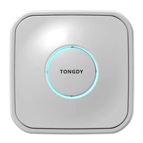
Tongdy MSD Series User manual

1/ 12
MSD IAQ Detector -User Manual
V.1805
MSD Indoor Air Quality Detector
—Commercial Grade IAQ products
Over 10-year experience in IAQ products design and
production, long-term exportation to Europe and
America, powerful strength guaranteed.
Rigorous design, professional test and calibration for
the commercial grade indoor air quality detectors.
High cost performance, be able to replace expensive
professional instruments, coordinate well with data
collection and analysis systems, making multipurpose real time monitoring
placements easier to be achieved.
Suitable for intelligent buildings, intelligent house systems, and air quality data
collection systems, green building evaluation systems, as well as ventilation
systems.
Specifications
General Data
Detection parameters
PM2.5; PM10; CO2; TVOC; air temperature & RH;
output
RS485/RTU (Modbus),RJ45 /Ethernet or WIFI @2.4 GHz 802.11b/g/n
Operating conditions
Temperature: -20~60℃Humidity:0~99%RH
Storage conditions
Temperature: -10℃~50℃Humidity: 0~95%RH (non-condensation)
Power supply
18~24VDC; or 100~240VAC
Dimensions
130mm(W)×130mm(H)×45mm(T)
Housing materials and IP level
PC/ABS fire-proof material / IP20
Standard Approval
CE
PM2.5/PM10 Data
sensor
Laser particle sensor, Light scattering method
Measuring range
PM2.5: 0~1,000 μg/m3 PM10: 0~1,000 μg/m3
Display resolution
0.1μg/m3
Stability at 0
±5μg/m3
Accuracy
10% of reading (@15~35℃)
Temperature and Humidity Data
Sensor type
High precision digital integrated temperature and humidity sensor
Measuring Range
Temperature: -20℃~60℃/ Humidity: 0~99%RH
Output Resolution
Temperature: 0.01℃/ Humidity: 0.01%RH
Accuracy
Temperature: <±0.5℃@25℃Humidity: <±3.0%RH (@20%~80%RH)
CO2 Data

2/ 12
MSD IAQ Detector -User Manual
V.1805
sensor
Non-Dispersal Infrared Detector (NDIR)
Measuring range
0~5,000ppm
Output Resolution
1ppm
Accuracy
±40ppm + 3% of reading
TVOC Data
sensor
TVOC
Measuring range
0~3.5mg/m3
Output Resolution
0.001 mg/m3
Accuracy
±0.05mg+10% of reading
Version
V.1711
Models Guide
Model.
PM2.5
PM10
Temp/
RH
CO2
TVOC
18~24VDC
Power supply
100~240VAC
Power supply
outputs
MSD-1618C
●
●
●
●
●
●
RS485
(Modbus
RTU)
MSD-1618D
●
●
●
●
●
●
MSD-1613C
●
●
●
●
●
MSD-1613D
●
●
●
●
●
MSD-1628C
●
●
●
●
●
●
WIFI
MSD-1628D
●
●
●
●
●
●
MSD-1623C
●
●
●
●
●
MSD-1623D
●
●
●
●
●
MSD-1638C
●
●
●
●
●
●
RJ45
MSD-1638D
●
●
●
●
●
●
MSD-1633C
●
●
●
●
●
MSD-1633D
●
●
●
●
●
Dimension and Mounting Holes

3/ 12
MSD IAQ Detector -User Manual
V.1805
Installation
1. To separate the backboard and the detector, rotate the backboard clockwise according to the
direction of the arrow (Pic.1&Pic.2).
2. Use a screwdriver to pry the threading hole on the backboard, and remove the cover of the
threading hole (Pic. 3).
3. Let the cable on the wall go through the threading hole (Pic.4 &Pic.5).
4. Unplug the terminal block from the contact pin (Pic.6).
5. Contact the cable to the terminal block (Pic.11&Pic.12), then tightly lock the mounting screw
(Pic.7).
6. Plug the contacted terminal block back into the contact pin (Pic.8).

4/ 12
MSD IAQ Detector -User Manual
V.1805
7.Aim the dot located in the middle of two arrows on the side of the detector with the vertical lines on
the backboard (Pic.9). Then rotate detector following the „FIX‟ direction until it‟s tight (Pic.10).
The installation is completed
Work Indicator
There is a circle ring of indicator light in the center of the housing. This indicator light is used to show
concentration range of measured value.
This indicator light can be controlled by any of measured values of among PM2.5 or CO2 or TVOC
through RS485 communication command, and change the color of indicator light depending on the
concentration.
Meanwhile, the measured value of the change of indicator light can be selected with one minute
average value or one hour average value of 24 hours average value in the communication
command.
The indicating light is controlled by one minute average value of PM2.5 as factory default.
DIP switches can control the ring of indicator light Open, and Green light keeps ON constantly, and
Turn Off the indicating light. Please see the following details.
DIP1
DIP2
DIP3
Green Normally ON
OFF
OFF
ON
Three-color Indicator
ON
ON
OFF
Default
Indicator OFF
OFF
OFF
OFF

5/ 12
MSD IAQ Detector -User Manual
V.1805
Active indicators
There is a light ring in the middle of the shell, which indicates the measuring range of CO2
concentration.
The indicator light can be chosen to be controlled by PM2.5, CO2 or TVOC using the Modbus
RS485 interface, and varies according to its concentration.
The measurement value that changes the indicator light can be the average value of one minute,
one hour or 24 hours in the communication instruction.
Factory Default:The light is controlled by the average PM2.5 measurement value of one minute.
Below is indicator color changes corresponding to the measured arrange:
PM2.5 <35ug/m3Green, 35~75ug/ m3Yellow, >75ug/m3Red
CO2 <600ppm Green, 600~1000ppm Yellow, >1000ppm Red
TVOC <0.25mg/m3 Green, 0.25~0.50mg/m3 Yellow, >0.50mg/m3Red
WIFI Settings
In the side of the MSD, there is a reset button in the
hole under “RESET”.
1. After the MSD is power on, insert a thin rod
(a paper clip or a toothpick, etc.) in the RESET hole,
and long press the RESET button for 6 seconds
2. Open the WLAN function of the mobile device, search "MXCHIP_" at the beginning of hot spots,
then connect it.
Note: researched WIFI hotspot is like MXCHIP_07E711, MXCHIP_ is an invariant format, 07E711
is a unique serial number for a WIFI module. Different WIFI modules have different serial numbers.
It will be shown on the surface of the WIFI module.
3. Use the browser of the mobile device, land the site 10.10.10.1
4. If you need to log into the account,
input User Name:admin,
Password:admin. Then “LOG IN”.

6/ 12
MSD IAQ Detector -User Manual
V.1805
5. At this point, get into the WIFI module Settings interface. We will need to modify the parameters
setting. The majority changes concentrate in ”Wifi Mode Select”, ”Station Mode Setting” and
”Network Setting”.
This interface language is default in Chinese, users can switch to English interface in the upper
right-hand corner.
6. On the right side of the interface, Select "Wifi Mode Select", and in the interface, click and select
“Station Mode”, then “Save”.
7. At this point, the restart module prompts appear in the interface, be careful NOT to click "Yes".
After all the parameters are set, restart the module at all.
If customers are not careful to restart the module, need to start again from step 1.
8. On the right side of the interface, select " Station Mode Setting", and in the interface, click "Scan"
directly, then connect to the hot spots.
9. In the interface, select the hot spot which the device will be connected with, such as "TONGDY_3",
then confirm it. Back to the previous interface, encryption based hot spots can be decided on
whether you need encryption or not. Does not need encryption: Disable; Encryption: Enable.
When you choose to need encryption, you need to key in a password to connect to the hot spots in
the increased option, finally "Save". The same do not restart the module.
10. On the right side of the interface, select "Network Setting", and in the interface, for “protocol”

7/ 12
MSD IAQ Detector -User Manual
V.1805
click and select "TCP Client" and "save". The same do not restart the module.
11. After entering other interface, and then get back to the "Network Setting" interface, shown as the
following figure, in the “remote port” and the “server address”, key in the server information where
the device will upload data, for example, the corresponding parameters of Qlear platform.
Remote Port: 20011
Server Address (IP):119.254.103.119
12. At this point all the parameter settings are done, restart the module.
13. When the module restarts successfully, there will be the following interface.
14. Set up completed, now you can add equipment, and check data on the corresponding server
site.

8/ 12
MSD IAQ Detector -User Manual
V.1805
Modbus RS485 Communication Parameters
Mode: Modbus RTU (MSB First)
Baud Rate: 1-4800;2-9600;3-14400;4-19200;5-38400;6-56000;7-57600;8-115200
Default: 2-9600bps
Start Bits: 1
Data Bits: 8
Stop Bits: 1 / 2 Default: 1
Parity: None / Odd / Even Default: None
Register Map
Support Function: 3 4 6 16
Please contact with sales to ask for Modbus Protocol document.
RJ45 Communications Configuration Instructions
1. Create virtual serial port
First install USR-VCOM and Modbus Poll on PC.
1.1 USR-K2 network port restore factory settings
Device in the power-off state, hold down the button
"RESET" on the bottom of the device, then power on the device again, after 5 seconds, release the
button. If the RJ45 module is the first configuration, no need to reset.
Open software,in the open interface, click on the “create automatically”.
The software will automatically find the device, select the device demanded, and click on the "next",
then, finally click on the "finish".

9/ 12
MSD IAQ Detector -User Manual
V.1805
At this point, the status bar will show "finish->COM2", and pop up dialog box "A virtual serial port is
created". Remember the "COM2" virtual serial port. In the following step, the device address
settings will need it.
2. Modify the IP and gateway for the PC connection
Only when IP and gateway are in the same frequency band, and are specified parameters, PC can
be connected, and set the USR-K2 port.
Enter PC local connection, in the pop-up "local connection state" get into the "property".
Double click on the “Internet protocol version 4 (TCP/IPv4)” to set the parameters, the specific
parameters are as follows

10 / 12
MSD IAQ Detector -User Manual
V.1805
Finally, click the „OK‟ to save the settings.
3. Configure USR-K2 parameters
3.1. USR-K2 network port restore factory settings.
Device in the power-off state, hold down the button "RESET" on the bottom of the device, then
power on the device again, after 5 seconds, release the button.
3.2 In the PC browser change into the "192.168.0.7", on the authentication page, enter the “admin”
for both the user name and password.
3.3 In the interface, mainly set the "Local IP Config" and the "RS232/RS485" two settings.
3.3.1 In the "Local IP Config" interface, IP mode select the "DHCP/Auto IP", and save.

11 / 12
MSD IAQ Detector -User Manual
V.1805
3.3.2 In the "RS232/RS485" interface, set parameters according to the QLEAR site, and save.
Specific settings as shown below
If the customer does not use the site to collect data, the corresponding parameters will make the
corresponding changes.
3.4 Set up completed, click on the "Reset Module", then the system will pop up the prompt of set up
successfully.
At this point, the device with USR-K2 network port, can upload monitoring data to the QLEAR site
through the Ethernet, and the user can check the data as needed.
Special Notice
MSD is designed for detecting indoor air quality. The product contains multiple gas sensors and dust
sensors, so the product should not be used in construction site or decoration site. If there is going to
be a construction project, the MSD product should be removed until the project is over.
In addition, MSD is a precise measuring device, if customers need to decorate the house after
installation the unit, please protect it by wrappages from paint coating and dust entering the unit.
Do not apply the MSD cover with other pigments, avoid plugging stoma, and paint into the MSD gas
chamber.
MSD is suitable for ceiling installation, wall installation. Do not use this product outdoors straightly.

12 / 12
MSD IAQ Detector -User Manual
V.1805
Product installation location should be selected: to prevent direct sunlight, away from the heat
source, away from the power or electrostatic precipitator equipment to avoid affecting product
accuracy.
The product should avoid dropping, impact caused by sensor beam deviation in the gas chamber
can lead deviation of CO2 measurement; The product should avoid long-term exposure to high
concentrations of total organic volatile gases, or sensor poisoning cannot be restored. For example,
the concentration is several times greater than the MSD TVOC range. When multiple MSDs are
wired and connected and sharing a power supply, make sure that the power supply wiring uses the
polarity of the power supply at the same name and that the wrong connection will cause the damage
of equipment.
The product should be maintained every half a year after started using, if the decoration or gray
environment or larger environment, the maintenance interval should be shorten. Maintenance
includes: clean the strainer, use an air pump or air suction tube to clean the dust inside the product.
Each time after being placed in construction site, the product needs to be maintained to keep on
normal using. If the measured value deviation, or interring dust and debris cannot be cleaned,
please go back to the factory to re-clean and calibration (paid maintenance).
Do not use the cigarette to test PM2.5 measurements. Because most of the cigarette particles are in
0.1 to 0.5 microns. While particles are<0.3 micron, the resolution of laser detection is greatly
reduced, so the cigarette concentration does not represent the true PM2.5 concentration. A 1/3
burning cigarette placed in a sealed box, the concentration will be higher than 10000ug / m3. Blow a
cigarette smoke to the box and then close the box, the concentration is also more than 5000ug / m3.
Therefore, PM2.5 measurements with cigarettes can cause too much deviation of the measured
values.
Tongdy Sensing Technology Corporation
http://www.tongdy.com
email: erica.hu@tongdy.com
tel: +86 10 59738930
add: Building #8, Courtyard #9, Dijin Road, Haidian Dist., Beijing 100095, China
This manual suits for next models
11
Table of contents
Other Tongdy Security Sensor manuals
Popular Security Sensor manuals by other brands
C.P. Electronics
C.P. Electronics MWS5-DD-SA-C installation guide
BIG TREE TECH
BIG TREE TECH SFS V2.0 manual
HIK VISION
HIK VISION DS-PDP15P-EG2-WB quick start guide
C.P. Electronics
C.P. Electronics SPIR-F/C/IP Product guide
C.P. Electronics
C.P. Electronics MWS6-PRM-VFC-NC installation guide
Paradox
Paradox NV37MX installation manual
