TONGHER TH-Mars 2 User manual

ELECTIRC FENCE
ENERGIZER
INSTALLATION AND USER MANUAL
(TH-Mars 2 / ES2,TH-Mars 5 / ES5)
Thank you for purchasing this Energizer
All right reserved

INSTALLATION AND USER MANUAL
- 1 -
WARNING
Please read all instructions before using the Energizer
DO NOT connect the fence to any other electric device.
• Lightning may strike your fence. A severe electric shock hazard exists to anything connected
to the fence or in near proximity to the grounding system.
• If connecting Energizer to AC power source, only use the provided AC adapter. The Energizer
connected to AC power shall be covered adequately to protect it from rain, snow or other moisture.
Keep out of reach of children.
• DO NOT Charge the battery with a battery charger while the Energizer is connected.
Disconnect and remove battery if re-charging is necessary.
• DO NOT connect more than one Energizer to the fence at one time.
• DO NOT connect two fences to the same Energizer.
• Keep fence at least 2 yards away from other fences with metal posts.
• DO NOT connect Energizer to barbed wire or razor wire.
• DO NOT install fence or grounding system within 10 yards of electrical power lines,
telephone lines, or telecommunications equipment.
• If running leads underground, use insulated wire and conduit rated for a minimum of 12,000 volts.
Prevent water from entering conduit.
• Keep young children away from the electric fence at all times.
• DO NOT touch the fence with head, neck or torso.
• DO NOT climb over, through or under a multi-wire electric fence. Use a gate or disconnect
the fence wires to cross.
• DO NOT put electric fence in areas of public access.
• Clearly mark the electric fence in several locations if located where people unfamiliar with the
fence may come into its proximity. Check your local and state laws regarding placement of electric
fences.
• Keep fence clear of obstructions or other objects that could potentially cause a person or
animal to become entangled in the fence.
• DO NOT use a water pipe, well, or your main power system ground as the ground for your
Energizer. If lightning were to strike the fence, the current could travel through the system causing a
severe electrical shock hazard.
• Place the grounding rod in a location that will not cause a person or animal to trip into fence or be
trapped between the ground wire and the fence.
• Always mount the Energizer securely such that it will not fall if bumped by an animal or person.
• Disconnect Energizer if conditions are extremely dry and represent high risk of fire.
• Keep combustible materials away from fence, Energizer and battery.

INSTALLATION AND USER MANUAL
- 2 -
Contents
1. About the electric fence energizer ---------------------------------------------------------------------------1
How does an electric fencing system work?
2. TH-Mars 2 Mars 5
2.1. Main features ---------------------------------------------------------------------------------------------2
2.2. Parts of the energizer------------------------------------------------------------------------------------3
2.3. Operation mode------------------------------------------------------------------------------------------4
2.4. Timer--------------------------------------------------------------------------------------------------------4
3. TH-Mars ES2 Mars ES5-------------------------------------------------------------------------------------------5
3.1. Main features---------------------------------------------------------------------------------------------5
3.2. Indication and setting-----------------------------------------------------------------------------------5
4. Installing the Electric Fence Energizer -----------------------------------------------------------------------6
4.1 Connecting to the power source ---------------------------------------------------------------------6
-mains power
-battery
-solar/battery
4.2 Install the energizer-------------------------------------------------------------------------------------8
4.3 Install the earthing system----------------------------------------------------------------------------10
4.4 Lead-out from the energizer--------------------------------------------------------------------------13
4.5 Post and wire spacings---------------------------------------------------------------------------------14
4.6 warning sign----------------------------------------------------------------------------------------------14
4.7 Safety requirements ------------------------------------------------------------------------------------14
5. Trouble-shooting-------------------------------------------------------------------------------------------------15
6. Maintenance------------------------------------------------------------------------------------------------------17
7. Manufacturer Warranty----------------------------------------------------------------------------------------17
8. Contact information---------------------------------------------------------------------------------------------17

Operator’s Manual
This manual is designed to ensure you achieve optimum results from your Electric Fence Energizer.
To ensure maximum output with minimum complications and optimum safety, we advise you to
follow the guidelines carefully concerning the correct installation of your fence energizer and the
required earthing system. Anything less will substantially affect the performance of the energizer
and can result in unnecessary complications and installation expense.
About the electric fence energizer
This Electric Fence Energizer is a comprehensive perimeter or strip fencing energizer and is an ideal
solution for those who want a simple, efficient and cost-effective system to power their fences.
It is easy to install and can be operated using either AC mains power, 12 volt (v) deep cycle
lead-acid/gel battery or in conjunction with a 30/40/50 or other watt (w) solar panel, making this a
suitable system for larger scale settings where no mains power is available. As a combination, fixed
or portable system, the Electric Fence Energizer provides flexibility with pasture management and is
the ideal solution for short or long-term animal control or rotational crop grazing
How does an electric fencing system work?
An electric current, generated from an energizer
which is earthed, travels along a fence wire as a
pulse. The circuit between the fence and the ground
is completed when an animal touches the fence
wire and consequently receives a short, sharp but
safe shock. This provides enough of a deterrent to
an animal, making the electric fence a psychological
barrier rather than a physical one.
TH-MARS SERIES PRODUCT SPECIFICATIONS
TH-MARS 2
TH-MARS ES2
TH-MARS 5
TH-MARS ES5
TH-MARS 6
Power supply 12V(110-240V 50HZ/60HZ)
Interval Period 1.2 / 2.0 s
1.2 / 2.0 s 1.2 / 2.0 s
1.2 / 2.0 s 1.2 / 2.0 s
LCD shows working Yes NO Yes NO YES
Consumption using a
power adaptor
1.92W 1.92W 2.4W 2.4W 2.85W
Timer Option NO Option NO Option
Intelligent fault
self-detection
YES YES YES YES YES
Output voltage
adjustment
Yes NO Yes NO Yes
Input current 160mA 160mA 200mA 200mA 220mA
Peak output voltage
(NO LOAD) 10 kV 10 kV 10 kV 10 kV 12 kV
Output voltage(500Ω)
4.5kv 4.5kv 4.5kv 4.5kv 6.0kv
Stored energy 2.9 J 2.9 J 5.4 J 5.4 J 6.3J
Km Multi Wire Fence 25km 25km 35km 35km 39km
Tongher Recommends
8km 8km 10km 10km 12km

INSTALLATION AND USER MANUAL
- 2 -
2. TH-Mars 2 Mars 5
2.1 Main features :
Powered by: AC mains power or, 12v deep cycle lead-acid/gel battery (not included) 30-60w
solar panel (not included) in conjunction with a 12v battery as above
6 operating modes including a cost-efficient day/night full/half power save
2 different pulse intervals of 1.5 seconds and 2.5 seconds
2 different max output of full and half energy
LCD shows the energizer working state, voltage , interval time, setting etc.
LED display the energizer working states, power/on/shock
Waterproof and dustproof IP44
Timer(Option)
Performance Characteristics
output voltage: 7-12 kv
pulse width: 100 us (1/1000 second)
Stored energy: 2 / 5 joules
Consumption(Max):
Mars 2 : 1.92 watt
Mars 5 : 2.4 watt
Package Contents
1 x Electric Fence Energizer
1 x Mains power adaptor
1 x Lead-out cable (red) to connect Energizer to fence
1 x Earthing cable (green) to connect Energizer to earthing system
1 x Set of leads to connect Energizer to 12 v deep cycle lead-acid/gel battery option (red and
black clips)
1 x user manual
1 x box packaging

INSTALLATION AND USER MANUAL
- 3 -
2.2 Parts of the energizer
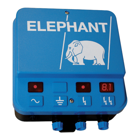
Power – Should be blue when properly connected to a 110v outlet or a fully charged 12v
deep cycle battery.
Status – Should be red when the energizer is producing voltage.
If the Status light is not illuminated, then check the energizer.
Shock indication
Flashing indicate the shock from energizer
Sensor – Light sensor for controlling pulse speed on Short Day/Long Night or Long
Day/Short Night operational modes.

INSTALLATION AND USER MANUAL
- 4 -
2.3 operation mode:
The working state can be controlled by these two buttons(UP/DOWN)
Hold-on mode: The Power LED indicator should be blue. Digital display will show
Output Voltage at 0kv and the Input Power Voltage. Status LED indicator should not
be lit. When in the On-Hold mode, the energizer will not generate a pulse.
Full energy mode: Energizer pulse will be every 1.2 seconds. The Power LED
indicator should be blue. Status LED indicator should be red. Digital display will
show Output Voltage at the energizer as well as the Input Power Voltage.
Reduced Energy Mode: Energizer power is reduced by 25%. The energizer pulse will
be every 1.2 seconds. The Power LED indicator should be blue. Status LED indicator
should be red. Digital display will show Output Voltage at the energizer as well as
the Input Power Voltage.
Short-day, long-night mode : Daytime pulse will be every 1.2 seconds, night pulse
will be every 2 seconds. The Power LED indicator should be blue. Status LED
indicator should be red. Digital display will show Output Voltage at the energizer as
well as the Input Power Voltage.
Long-day, short-night mode : Daytime pulse will be every 2 seconds, night pulse will
be every 1.2 seconds The Power LED indicator should be blue. Status LED indicator
should be red. Digital display will show Output Voltage at the energizer as well as
the Input Power Voltage.
Battery Saving Mode: Energizer power is reduced by 25%. The energizer pulse will
be every 2 seconds. The Power LED indicator should be blue. Status LED indicator
should be red. Digital display will show Output Voltage at the energizer as well as
the Input Power Voltage.
When this energizer is plugged into a standard 110v-240v outlet power source, the Power Voltage
display will read close to 12.6v. When the energizer is attached to a 12v deep cycle battery,
the Power Voltage should read between 12.2 and 13.6 volts. If the voltage of the battery reads
lower than 12.2volts that indicates it is time to recharge the battery.
2.4 Timer
There is extra function for some customer – timer
This timer is base on weekly , we can set the timer using the buttons “UP” “DOWN”.
1. Timer without setting : None stop working
2. Start and stop in the same day but different time, means repeat daily working
3. Start and stop in different day , means repeat weekly working
(More setting operation please refer to our technology support and Reseller)
Setting
1. Push “UP” to Hold-on mode
2. Push “DOWN” 5 Seconds,and enter setting interface.
3. Push “UP” to modify the value, and DOWN to move to next setting bit.
4. “Y” submit the setting ,”N” cancel the setting
Top two rows is the current time

INSTALLATION AND USER MANUAL
- 5 -
TH-Mars ES2 and TH-Mars ES5
3.1 Main features:
Powered by: AC mains power or, 12 v deep cycle lead-acid/gel battery (not included) 30-60 w
solar panel (not included) in conjunction with a 12 v battery as above
5 operating modes
2 different pulse intervals of 1.5 seconds and 2.5 seconds
2 different max output of full and half energy
LED display the energizer working states, power/on/shock
Waterproof and dustproof
Performance Characteristics
output voltage: 7-10 kv
pulse width: 100 us(1/1000 second)
Output energy: 2 / 5 joules
Consumption(Max):
Mars ES 2 : 1.92 watt
Mars ES 5 : 2.4 watt
3.2 Indication and setting
Power light/state (Green)
Power supply is connected from mains power or battery
On: power input is good
1 Hz flash : power is low , energizer will be deactivated
E1 inner error
0.5 Hz flash: E2 inner error
working states(Red) :output energy
On: full power output
Flash : half power output
working states(Red) : interval time
On: 2 second
Flash : 1 second
Change the working state by pushing “UP” and “DOWN”

INSTALLATION AND USER MANUAL
- 6 -
3. Installing the Electric Fence Energizer
4.1 Connecting to the power source
The Electric Fence Energizer can operate using mains power, 12 v deep cycle lead-acid/gel battery
or solar and lead-acid/gel battery.
Mains power
1. Attach the mains power adaptor to the Energizer
– insertion point on reverse side of unit – and
plug into the mains power socket
2. DO NOT turn the mains power on until the
powered fence system is fully constructed and
you are ready to use it
Battery (not included)
1. Always use a 12 v deep cycle lead-acid/gel battery
2. Site the battery in a well-ventilated area
3. Attach the battery cable to the Energizer – insertion
point on the reverse of the unit
4. Connect the RED clip to the POSITIVE (+) terminal of
the external battery
5. Connect the BLACK clip to the NEGATIVE (-)
terminal of the external battery
Battery: Lead-acid or other kind of battery with voltage
more than 12 v.
Solar/battery (not included)
1. The Electric Fence Energizer is compatible
with a minimum 40 w solar fence panel and a
12 v deep cycle lead-acid/gel battery
2. Set up the solar panel as per the instructions
enclosed with it using the appropriate
regulator. If you bought your solar panel it
will include the correct charging regulator.
3. Set up the 12 v deep cycle lead-acid/gel
battery as per above instructions for Battery
Solar panel: voltage more than 12 v solar controller or
battery is necessary)

INSTALLATION AND USER MANUAL
- 7 -
The best place to site the Electric Fence Energizer depends upon which of the three power supplies
you choose; mains power, battery or solar/battery. See table 1
Power supply Benefits Energizer best positioned
Mains power Cost-effective
Reliable
Mount out of reach of children & animals
Position near to a power point either inside or
outdoors
Avoid long lead-outs running adjacent to power or
telecommunications cables or other earthing systems
Site at least 10 metres (m) away from any other
electric or telecommunications cables or earth systems
If possible, site the Energizer in the middle of the
fencing system
Battery Practical choice in
areas of inaccessible
mains power
Electric Fence
Energizer can be fitted
with a 12 v deep cycle
lead-acid/gel battery*
(80 Ah is
recommended)
Mount out of reach of children & animals
Position near a power point if using combination
mains power/battery and follow guidelines as for mains
power
Keep Energizer off the ground if siting outside to
protect electrical components from insect and moisture
damage
If necessary, build a protective box/fence around the
Energizer
If possible, site the Energizer in the middle of the
fencing system
Solar Logical choice for
remote areas where no
mains power available
For the Electric Fence
Energizer a 12-volt
deep cycle
lead-acid/gel
battery
(50-80 Ah is
recommended) plus a
30-50 w solar
panel(depend on the
sunlight intensity )
Mount out of reach of children & animals
Keep Energizer off the ground to protect electrical
components from insect, livestock and moisture damage
If necessary, build a protective box/fence around the
Energizer
If possible, site the Energizer & solar panel in the
middle of the fencing system
Position the solar panel to face north in the southern
hemisphere and south in the northern hemisphere.
Protect from possible damage by livestock
Some adjustment of the panel may be required to
accommodate the midday, winter sun
Table : Siting the energizer depending on the choice of power supply
Important: If using a rechargeable battery, choose one that withstands regular, charge and
discharge cycles without damage, such as a marine or deep cycle type. Do not use automotive
batteries because they supply high current for short periods and may not provide the continual
output you require.

INSTALLATION AND USER MANUAL
- 8 -
4.2 Install the energizer
1. Mount the energizer on a wall ,under cover ,out of reach of children .install where there is no
risk of the energizer incurring fire ,mechanical , or water damage and if possible away from
heavy electrical equipment,(e.g. pumps or other item that may cause electrical interference).
Noted: install the energizer in a frequently accessed place, the output bar graph gives valuable
information that can save time and help prevent costly problems.
2. Choose a mounting surface of sufficient strength,(e.g. stud , dwang or plywood panel).
Mounting surface needs to be robust and of sufficient thickness to properly contain the
mounting screws. On the mounting surface , mark where the screw for the top keyhole of the
mounting bracket is to be fixed . ensure this is at the correct mounting height you require for
the energizer, Drill a small pilot fixing hole. Install the tek fixing screws and check the clearance
for the mounting bracket to slide over the screw head.
3. Carefully hang the energizer over the screw
Permanent inside installation
Drill 2 holes on the horizontal. Fix the screws (not supplied) leaving a 4mm gap between the
head of the screw and the wall. Once in place, line the back of the energizer with the mounting
screws and slide down into place.

INSTALLATION AND USER MANUAL
- 9 -
Temporary outdoor installation
Mount to a wooden fence post using 1 central screw (not supplied), leaving a 4mm gap
between the head of the screw and the post. Once in place, line the back of the energizer
with the mounting screw and slide down into place. Alternatively, the handle of the energizer
can be hung over a tread-in at the end of the fence, away from animals and children and high
enough to avoid vegetation.

INSTALLATION AND USER MANUAL
- 10 -
3.3 Install the earthing system
Poor earthing is the most common reason for poor electric fence performance.
It is very important to have a high quality earth system.
This is a vital component of any powered fence system. Electrons travelling from the Energizer must
complete a circuit in order to give the animal an electric shock. From the Energizer, electrons travel
along the insulated fence wires, through the animal’s body, through the soil to the earthing system
– a number of connected earth stakes that absorb electrons in the soil - then return to the Energizer.
If an electric fence is not earthed correctly, it will be much less effective – see table bellow.
Known factors What happens? What’s the solution?
Dry, sandy pumice
soil types
Allows electrons to disperse
rather than be absorbed
completely by earthing stakes.
Reduces
effectiveness.
If possible, choose a better location or an
alternative method of earthing such as a
bentonite salt earth system
Consider additional earthing stakes
Water earthing system to improve soil
conductivity
Weeds/vegetation
touching live fence
wires
Electrons leak causing fence
circuit to ,“short” and voltage
to drop
Check entire fence lines regularly
Weed/grass management to ensure
nothing touches the fence wires
Trim back over-hanging tree branches
which may also touch the fence wires
Rusty or corroded
earthing stakes
Do not conduct electrons Use clean, GALVANISED or copper
coasted earth stakes
Animal urine and
manure
Long term exposure corrodes
earth stakes
Site earthing system away from animal
excreta
Interference Ensure
the earthing system
is sited at least 10
Interference Ensure the earthing system is sited at
least 10 m away from any mains earth
system and 20 m from any dairy-shed
pipework
Steel or iron-clad
buildings
Interference Do not connect earthing system to metal
buildings
Machinery
or livestock
Can damage components of
earthing system
Position earthing system away from
livestock or other traffic thoroughfares
Mixed metals within
the earthing system
Electrolysis , causing some
components of the earthing
system to corrode
Do not mix metals of differing
conductivity e.g. never use copper wire
directly onto galvanized earth stakes
Table 2: Factors known to affect an earthing system

INSTALLATION AND USER MANUAL
- 11 -
Location of the earthing system
The following examples are to help you locate a suitable position for your earthing system given a
variety of conditions:
1. All live earthing system: Recommended where the soil is highly conductive, i.e. most moist soils.
2. Earth-wire return earthing system: Where soils are not conductive e.g. dry, sandy, pumice soils
as well as frozen soils or snow conditions, an earth-return wire should be used in conjunction
with the earthing system – as per diagram
3. Bentonite salt earthing system: A known alternative for extremely dry soil conditions. A mixture
of bentonite and coarse salt (10 lbs bentonite : 5 lbs coarse salt, mixed into a slurry) is placed in
and around each earth stake. The salt attracts moisture making it highly conductive, while the
bentonite retains moisture over prolonged periods.
Note: For this particular application stainless steel earth stakes are required to prevent salt
corrosion and should be spaced 10 m apart.

INSTALLATION AND USER MANUAL
- 12 -
Earth stakes
1. For normal earthing use clean, GALVANISED / copper plating earth stakes.
2. The Electric Fence Energizer output capacity is 2-5 joules. A minimum of 3 earth stakes is
recommended, each 1-2 m in length. Depending on the location and conditions of the earthing
system, additional stakes may be required.
3. Space the earth stakes at least 3 m apart (10 m apart if using the bentonite salt earthing system)
then drive them deeply into the soil leaving a minimum of 10 centimetres (cms) above ground
level for the single connecting cable Join the earth stakes in a continuous series using clamps
and insulated connecting cable
4. If using the bentonite salt earthing system, use stainless steel earth stakes and space them at
least 10 m apart
Connecting the earthing system to the Energizer
The Electric Fence Energizer comes with an earthing cable suitable for portable powered fencing
which can be connected as follows:
1. Unscrew the BLACK cap on the Energizer unit
2. Insert the rod of the GREEN earthing cable through the hole of the screw
3. Replace the BLACK cap, tighten to secure the rod in place
4. Attach the GREEN clip at the other end of the cable to one of the EARTH STAKES
5. Test the earthing system
Testing the earthing system
Ideally, you should perform this test at least ONCE each year and also during any dry season. This
ensures the earthing capacity is sufficient to meet the demands of the Electric Fence Energizer. To
perform the test you will need:
Several steel rods or lengths of pipe Fence tester, galvanised metal stake at least 200 mm in length
1. Turn OFF the Energizer.
2. Using several steel rods or lengths of pipe, short circuit the fence by laying these against the
fence at least 100 m away from the Energizer. In dry or sandy soil conditions, drive the rods up
to 30 cms into the soil.
3. Turn ON the Energizer.
4. Measure the fence voltage using the fence tester. The reading should be 2kv or less. If not, put
more steel rods against the fence.
5. Now, check the earthing system by fully inserting the earth probe of the fence tester into the
surrounding soil and attach the clip to the last earth stake. The reading should be no more than
0.2 kv. If the reading is higher, the earthing system is insufficient and you should recheck the
entire system thoroughly.

INSTALLATION AND USER MANUAL
- 13 -
4.4 Lead-out from the energizer
The lead-out cable/wire, which can be installed overhead or underground, carries the electric
current from the Energizer to the fence. In order to maintain the full level of power, the lead-out
cable/wire should have as little resistance as possible.
Connecting the lead-out cable from the Energizer to the fence
The Electric Fence Energizer comes with a short length, low resistance lead-out cable which can be
connected as follows:
Unscrew the RED cap on the Energizer unit
Insert the rod of the RED lead-out cable through the hole of the screw
Replace the RED cap, tighten to secure the rod in place
Attach the RED clip at the other end of the cable, to the FENCE WIRE
Longer length lead-out cable/wire
Should you require a longer length lead-out cable/wire than the one supplied then you must
consider the following:
Choose lead-out cable/wire with low resistance i.e. the larger the diameter, the lower the
resistance
Table shows that a 2.5 mm or 12 gauge (g) wire has 2½ times the resistance than 4.0 mm or 8 g
wire. Remember, the lower the resistance, the better
Longer length lead-out cable/wire increases resistance leading to voltage loss
DO NOT use household electrical cable. It is intended for low voltage use only
NEVER use copper wire. Where copper joins galvanized wire, electrolysis occurs, destroying the
wire
NEVER use barbed wire
Use insulated cable, particularly if there is a possibility of contact with any earthing point
Wire size Resistance of wire (ohms/km)
Gauge(g) Wire diameter(mm)
8 g 4.0 mm 14 ohms/km
10 g 3.15 mm 22 ohms/km
12.5 g 2.5 mm 35 ohms/km
14 g 2.0 mm 54 ohms/km
16 g 1.6 mm 85 ohms/km
Table 3: DC resistance in ohms of a single galvanized steel fence wire over 1 km
Other helpful hints:
If running lead-out cable underground, feed it through a piece of plastic hose or pipe before
burying. This not only gives the lead-out cable protection but acts as a warning to anyone who may
dig in the area in the future
DO NOT install lead-out wire close to the ground where potential “leakage” through vegetation
will result in voltage loss
Keep stray wires well away from the lead-out cable/wire

INSTALLATION AND USER MANUAL
- 14 -
4.5 Post and wire spacings
Ideally, plan the fence line, avoiding rough, stony or steep areas. Build the fence with all wires
electrified to control your animal type. As a guide, the smaller the animal the more wires required,
for example; cattle 1-3 wires, sheep 4-5 wires and for goats and sheep, ensure the bottom wire is
150 mm above ground level to prevent them escaping beneath the fence line. The following are
some suggestions for post and wire spacings :
For more information on fence construction, please refer to our after sales department for tips on
Permanent Powered Fencing and Temporary Powered Fencing
4.6 Warning sign
A warning sign shall be fitted to every point where persons may gain ready access to the
conductors .Where an electric animal fence crosses a public pathway, a non electrified gate shall be
incorporated in the electric animal fence at that point or a crossing by means of stiles shall be
provided. At any such crossing, the adjacent electrified wires shall carry warning signs.
Any part of an electric animal fence that is installed along a public road or pathway shall be
identified at frequent intervals by warning signs securely fastened to the fence posts or firmly
clamped to the fence wires.
The inscription shall be indelible, inscribed on both sides of the warning sign and have a height
of at least 1” (25 mm).
4.7 Safety requirements
4.7.1. NEVER use more than ONE Energizer on one fence at any given time
4.7.2. The earthing system must be at least 10 m from the mains electrical earth
4.7.3. Try to avoid electric fence wires passing under or parallel to overhead power lines,
telephone lines or cables
4.7.4. If the crossing is unavoidable, make it as close to a right angle as possible
4.7.5. Electric fences near or under power lines should be no higher than 2 m (6 ft 8 ins)
4.7.6. All wires should be at least 5.5 m (18 ft) above ground when crossing a public road
4.7.7. Don’t use power poles to support electric fence or lead-out cable/wire
4.7.8. Electric fences bordering public walkways require regulation warning signs Regulation is
200 mm x 100 mm with 25 mm lettering
4.7.9. Signs should be located within 20 m of each end of the fence. Additional signs need to be
100 m apart on an electric fence which is adjacent to a public road or thoroughfare and 50 m in
urban areas
4.7.10. Under no circumstances should barbed or razor wire be electrified
4.7.11. Lightning Protection - If lightning strikes your electric fence it will damage your Energizer.
In areas prone to severe lightning, installing an earthing system to include a lightning diverter is
essential. These are generally available from your local Farm Supply Company. The lightning
diverter has its own earthing system which provides an alternative path for the lightning that
strikes the fence to reach the ground. It consists of separate earthing stakes from the Energizers
earthing system, (minimum of 3), and should be installed at least 20 m away from it. However,
incorporating a lightning diverter is not a guarantee for total protection, particularly when
there is a direct lightning strike to the fence or the energizer itself. Alternatively, completely
disconnect the energizer from the power source and earthing system during lightning storms.

INSTALLATION AND USER MANUAL
- 15 -
5.Trouble-shooting
A fence tester, is an essential piece of equipment required to monitor the electrical output along
the fence line, perform regular maintenance checks along the fence-lines as well as assisting to find
faults quickly and easily, should they occur. If your fence-line is registering less than the
recommended 3000 v on your fence tester then check the following:
Possible cause
Action
Energizer itself
If you require the energizer to power up greater distances, you will need to try a
more powerful Energizer. Alternatively, re-plan your powered fence system to
within the maximum capacity of the Energizer. Additional fence requirements will
require a second unit
Check the power supply:
Mains power - check the system is plugged in and switched on
-ensure all leads/cables are properly connected
Battery -check battery life and amount of stored energy
-revert to mains power if battery level below 10.8 v
Solar/Battery -check battery life and amount of stored energy
-change to back-up battery if level low or mains power if possible or
charge the battery on mains power
Earthing
System
Ensure there are a minimum of 3 earth stakes, more if soil conditions warrant it
Earth stakes must be at least 2 m long
Check that earth stakes are spaced 3 m apart and buried deeply in the soil
Check all connections to the earth stakes are secure
It is vital that all components of the earthing system are made of the same metal
Ensure the position for the earthing system is damp, preferably shaded and
high-mineral
content soil, if not, resite the earthing system
If there is a severe dry period, you may need to water the earthing system or
consider
alternatives such as re-siting your earthing system or using a bentonite/salt
mixture – refer
to page 6
Lead-out
cable/wire
Check the connection to the Energizer is secure
If using a longer length lead-out cable/wire to the one supplied, ensure a large
diameter,low resistance, cable/wire. Do not use household electrical cable, copper
wire or barbed wire
Ensure the wire is sufficiently insulated, particularly if sited underground
Check there are no stray wires and no vegetation touching the lead-out wire
Check all cable joins to ensure connections are insulated and secure

INSTALLATION AND USER MANUAL
- 16 -
Fence line Walk the entire fence perimeter tracing a fence tester along the line, checking
about every
100 m. If the short is serious the voltage will continue to drop until the fault is
reached
Check all joins in the wire to ensure they are secure
Check the fence wire itself for any signs of corrosion
Vegetation touching the fence line is the greatest cause of voltage loss. Maintain
fence
lines, ensuring weeds, low hanging branches and other vegetation growth are kept
away
from the fence lines. Ensure the wire position and tension is adequate to keep the
lines
above any vegetative growth
Radio
interference
Ensure the earthing system is highly conductive
Install the Energizer away from any mains power earthing system
Make certain the Energizer earth wire does not touch a building or anything
which could act as an aerial
Keep all radios and similar equipment away from the Energizer
Ensure the mains power supply is properly earthed and all components are in
good condition
Keep vegetation away from the Energizer itself
Telecommunic
ation
interference
can be
detected by
either:
i) Clicking
noises on
the telephone
line ii) Slow or
variable
internet
connection
Know where the telecommunications cables are. This includes buried and
overhead lines. You may need assistance here from your local telecommunications
company
DO NOT run the lead-out cable/wire or the fence wires, for any distance in
parallel with telecommunications wires
Lead-out cable/wire and fence wire must be sited at least 100m away from
telecommunications lines
Ensure the earthing system is sited at least 10m from telecommunications lines
and other earthing systems
Check all wires and connections along the entire perimeter of the powered fence
system and ensure they are in good condition
If the fault persists, find an alternate route for the lead-out cable/wire and fence
wire so that it runs away from the telecommunications lines rather than alongside
them

INSTALLATION AND USER MANUAL
- 17 -
6 . Maintenance
For a safe reliable electric fencing system, we recommend you follow these helpful tips:
6.1. Regularly wipe down the unit with a soft damp cloth to ensure that there is no build-up of
mould etc.
6.2. Do not use any abrasives which may damage the coating of the Energizer
6.3. Clean any connections and terminals which may be showing signs of corrosion
6.4. Perform a thorough test of the earthing system at least ONCE each year and also during any
dry season
6.5. Inspect fence lines regularly, clearing any weeds, low hanging branches or other vegetation in
direct contact with the wire
6.6. Check fence wire positions and tensions to ensure they are adequate to keep the fence lines
above vegetative growth
6.7. Ensure all fence wire insulators are intact and in good condition
7. Manufacturer Warranty
Our products are warranted to be free from defects in materials or workmanship for 1 year from
the date of purchase. Within this period, Manufacturer will, at its sole option, repair or replace any
components that fail in normal use. Such repairs or replacement will be made at no charge to the
customer for parts or labor, provided the customer shall be responsible for any transportation cost.
This warranty does not apply to: (i) cosmetic damage, such as scratches, nicks and dents; (ii)
consumable parts, such as batteries, unless product damage has occurred due to a defect in
materials or workmanship; (iii) damage caused by accident, abuse, misuse, water, flood, fire, or
other acts of nature or external causes; (iv) damage caused by service performed by anyone who is
not an authorized service provider of Manufacturer; (v) damage to a product that has been
modified or altered without the written permission of Manufacturer; or (vi) damage to a product
that has been connected to power cables that are not supplied by Manufacturer.In addition,
Manufacturer reserves the right to refuse warranty claims against products or services that are
obtained and/or used in contravention of the laws of any country.
Repairs have a 90 day warranty. If the unit sent in is still under its original warranty, then the new
warranty is 90 days or to the end of the original 1 year warranty, depending upon which is longer.
Contact information
Should you have any questions or concerns please do not hesitate to contact the team at:
Tongher tech
Tel:+86 13603022363
Website: www.tonghertech.com
E-mail: Jason@tonghertech.com
Shenzhen Huizhou
∙
CHINA
This manual suits for next models
3
Table of contents
Other TONGHER Power Supply manuals
Popular Power Supply manuals by other brands

EVGA
EVGA SuperNOVA NEX 650G Specifications
Vanguard Instruments
Vanguard Instruments UPS 2 Series Operating procedures

Powerten
Powerten P60 Series Operation manual
Tripp Lite
Tripp Lite PR10 owner's manual

Dynatronix
Dynatronix LT1200X SERIES operating manual
Schrack Technik
Schrack Technik AVARA Multi Power Series user manual
