Tonghui Electronics TH6400 Series User manual


TH64 Series Operation Manual
Contents
Contents
Chapter 1 Introduction................................................................................................................1
1.1 Introduction to Instrument.................................................................................. 1
1.2 Working Condition............................................................................................. 1
Chapter 2 Precautions for Usage................................................................................................2
2.1 Dimension and Weight.................................................................................................... 2
2.2 Safety Requirements........................................................................................................ 2
2.3 Electromagnetic Compatibility........................................................................................ 2
Chapter 3 Panel..........................................................................................................................4
3.1 Front panel ...................................................................................................................... 4
3.2 Rear panel........................................................................................................................ 5
3.3 Display ............................................................................................................................. 5
Chapter 4 Operation...................................................................................................................7
4.1 Output display ................................................................................................................. 7
4.1.1 Value setting................................................................................................................. 7
4.1.2 Output .......................................................................................................................... 7
4.2 CH SET.............................................................................................................................. 8
4.2.1 Voltage and current Set................................................................................................ 8
4.2.2 Max. Voltage Set........................................................................................................... 8
4.2.3 OVP Volt Set ................................................................................................................. 8
4.2.4 Time Set........................................................................................................................ 9
4.2.5 OVP Switch ................................................................................................................... 9
4.2.6 Time Switch .................................................................................................................. 9
4.2.7 SAVE VALUE.................................................................................................................. 9
4.3 CH File.............................................................................................................................. 9
4.3.1 Recall and delete ........................................................................................................ 10
4.4 Menu set........................................................................................................................ 10
4.4.1Language ..................................................................................................................... 10
4.4.2 Key voice..................................................................................................................... 11
4.4.3 P-Mem........................................................................................................................ 11

TH64 Series Operation Manual
Contents
4.4.4 R-Wait......................................................................................................................... 11
4.4.5 Bus Mode.................................................................................................................... 11
4.4.6 Baud Rate ................................................................................................................... 11
4.4.7 GPIB-Addr................................................................................................................... 11
4.4.8 Combine ..................................................................................................................... 11
4.4.9 Date ............................................................................................................................ 12
Chapter 5 Operation................................................................................................................ 13
Chapter 6 Interface and communication ................................................................................ 14
6.1 Remote Control ............................................................................................................. 14
6.1.1 RS232 description....................................................................................................... 14
6.1.1.1 Introduction of RS232 interface.............................................................................. 14
6.1.1.2 Communicate with PC............................................................................................. 15
6.1.2 GPIB interface............................................................................................................. 15
6.1.2.1 GPIB bus................................................................................................................... 15
6.1.2.2 GPIB bus................................................................................................................... 17
6.1.2.2 GPIB address............................................................................................................ 17
6.1.3 USB TMC remote control system ............................................................................... 17
6.1.3.1 Configuration........................................................................................................... 17
6.1.3.2 Install the driver ...................................................................................................... 17
6.1.4 USB CDC virtual serial port ......................................................................................... 19
6.1.4.1 System configuration............................................................................................... 19
6.1.4.2 Install the driver ...................................................................................................... 19
6.2 Command ...................................................................................................................... 19
6.2.1 Basic rule of command structure ............................................................................... 19
6.2.2 Command for reference............................................................................................. 20
6.2.2.1 The following GPIB command is supported ............................................................ 20
6.2.2.2 SCPI command......................................................................................................... 20
Chapter 7 Specification ........................................................................................................... 27

TH64 Series Operation Manual
Contents
Declaration
The descriptions contained in this manual may not cover all information about this instrument.
Introductions to the improvements of the instrument in performance, function, internal structure,
outer appearance, accessories, packing material, etc. are subject to change without notice. If you
find any inconformity of this manual with our instruments, please contact us for further consultation
by the address listed on the cover.

TH64 Series Operation Manual
1
Chapter 1 Introduction
Thank you for your purchase and use of our products. This chapter will introduce the basic
instrument performance, which is followed by notes of unpacking and installing.
1.1 Introduction to Instrument
TH6400 series is a programmable linear DC power supply with double range. The series of
instruments have powerful functions and superior performance. The use of LCD screen display
makes the display clear and menu operation easy, which adapt to the needs of rapid operation on the
production site and high precision and stability of high-precision laboratory. Also, being equipped
with RS232 interface, USB interface and GPIB interface, they are convenient for the instrument
used in remote operation of the computer.
Special features and benefits of the instrument are as follows:
⚫480*272 pixels, 24-bit color, 4.3-inch color TFT LCD screen, used to set the test conditions
and measurement results display
⚫Numeric keyboard operation
⚫High accuracy and high resolution
⚫Low ripple and low noise
⚫Intelligent fan control to save energy and reduce noise
⚫Software control and testing through the computer
⚫3 channel programmable voltage and current output
⚫Fine-tune the value with knobs and cursors
⚫The maximum timer setting time is 99999.9 seconds
1.2 Working Condition
⚫Power Connection
Power supply: 220V (1±10%)
Power supply frequencies: 50Hz/60Hz (1±5%)
Power range: <50VA
⚫Environment Temperature and humidity
Normal working temperature: 0℃ to 40℃ Humidity: < 90%RH
Reference working temperature: 20℃±8℃ Humidity: < 80%RH
Transport working temperature: 0℃~55℃ Humidity: 93%RH
⚫Warm-up
For accurate measurement, the warm-up time should not be less than 20 minutes.

TH64 Series Operation Manual
2
Chapter 2 Precautions for Usage
⚫Please do not use the tester in dusty, vibrative, direct sunlight and corrosive gases and
other adverse environments.
⚫When the instrument is not used for a long time, please put it in the original box or similar
box and stored in a ventilated room with temperature of 5℃~40℃ and relative humidity
less than 85% RH. Do not store the tester in a corrosive atmosphere containing harmful
impurities and should avoid direct sunlight.
⚫The instrument has been carefully designed to reduce clutter due to AC power input.
However, it should still be used under low noise conditions. If that is inevitable, please
install the power filter.
⚫There is cooling fan on the rear panel and cooling vents in the left and right case to avoid
influencing the accuracy due to internal temperature rise. Please make sure the instrument
is in good ventilation.
⚫Do not switch the instrument frequently to avoid loss of stored data.
2.1 Dimension and Weight
⚫Dimension (W*H*D): 218mm*88.8mm*473mm
⚫Weight: 12kg
2.2 Safety Requirements
This tester is a Class I safe equipment.
⚫Insulation resistance
In the reference working conditions, the insulation resistance between the power terminals
and the shell is not less than 50M.
In hot and humid transport conditions, the insulation resistance between the power
terminals and the shell is not less than 2M.
⚫Dielectric strength
In the reference working conditions, the power terminal and the shell can withstand for
one minute with no breakdown and flashover phenomenon of 1.5kV rated voltage and
50Hz frequency of AC voltage.
⚫Leakage current
The leakage current is not greater than 3.5mA.
2.3 Electromagnetic Compatibility
Power Transient Sensitivity, refer to requirements of GB6833.4.
Conducted Susceptibility, refer to requirements of GB6833.6.

TH64 Series Operation Manual
3
Radiated interference, refer to requirements of GB6833.10.
TH64 Series Operation Manual
4
Chapter 3 Panel
In this chapter, there is only rough description, please refer to more information in
chapter 4.
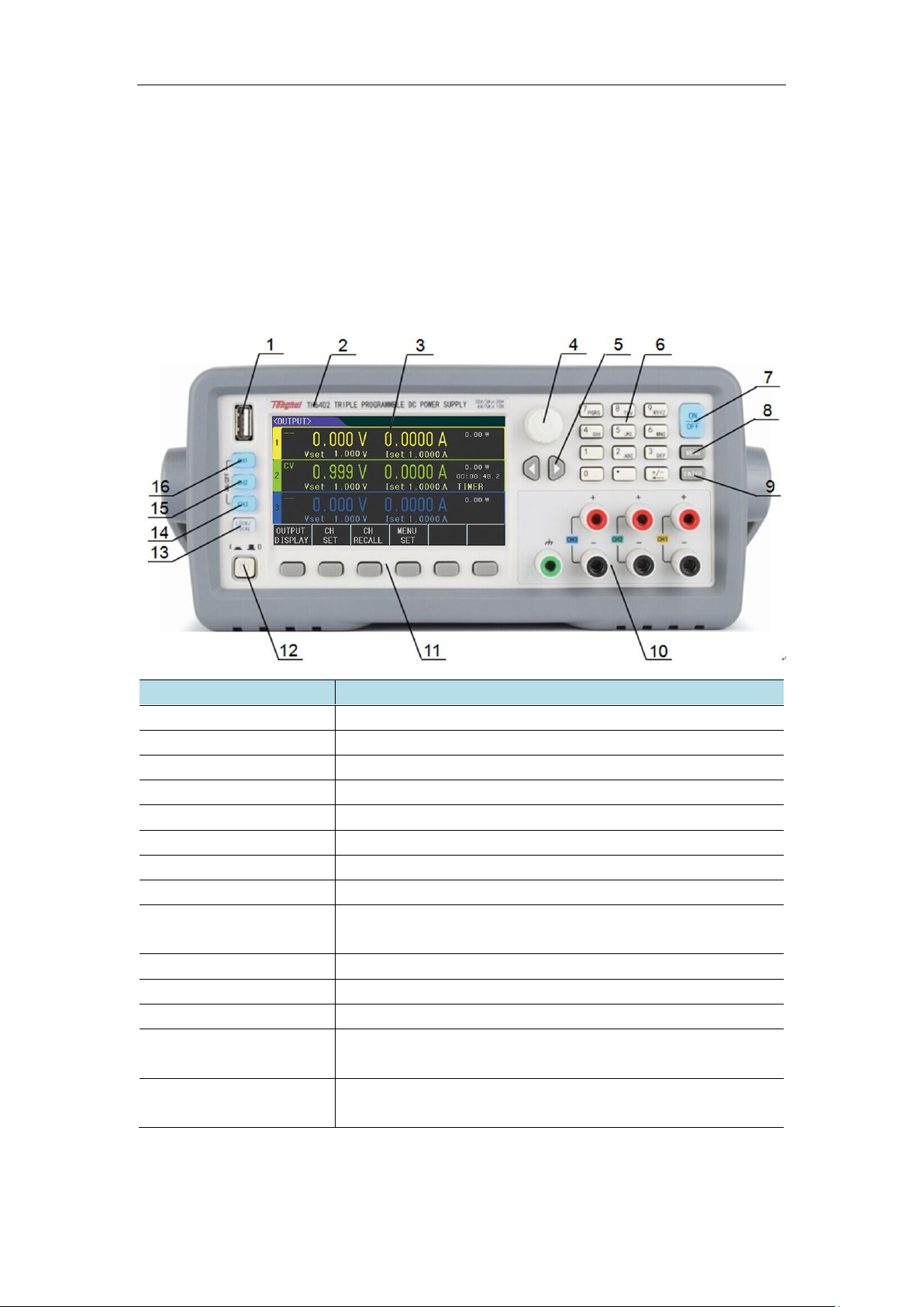
3.1 Front panel
Name
Function
① USB interface
Import or export the data via the USB interface
②Trademark and model
Mark the manufacturer and model of the instrument
③LCD display
480 × 272 pixels, 24-bit color, 4.3-inch color TFT LCD screen
④ Knob
Adjust the value or move the arrow cursor
⑤ Arrow keys
Left and right arrow keys for moving the cursor
⑥ Numeric keys
Input the specific values
⑦[ON/OFF] key
Turn on or off the three channel output simultaneously
⑧ [MENU] key
Quick access to menu interface
⑨ [ENTER] key
To input the data and can be used with the [LOCK/LOCAL] key
to take screenshots
⑩Output terminal
Front panel output ports, total three channels
⑪Software menu key
To set the display content
⑫Power switch
Power switch
⑬ [LOCK/LOCAL] key
To lock the key or switch the remote control and can be used with
the [ENTER] key to take screenshots
⑭Output key for 3
channels
Corresponding to the output or close button for three channels

TH64 Series Operation Manual
5
3.2 Rear panel
1
GPIB
Communicated with PC to build GPIB test
system
2
USB
Controlled by PC via USB DEVICE
3
RS232
Function is same as No.2
4
Power socket
Connecting 220V/50HZ AC power supply
5
Remote test
terminal
Same function as output in front panel, 4-
terminal sampling function is added
6
Nameplate
Record production date, model,
manufacturer
3.3 Display
(1.) Display menu zone: Display the name of current page

TH64 Series Operation Manual
6
(2.) Status and error information zone: Display the error information or
current working status.
(3.) Fast setting and display zone: In this zone, you can set the voltage,
current and real time sampling numbers & timing can be displayed .
(4.) Softkey menu zone: The content is flexibly, display the function
matched with current softkey

TH64 Series Operation Manual
7
Chapter 4 Operation
4.1 Output display
Press OUPUT DISPLAY to enter <OUTPUT> page
<OUTPUT>is displayed as below
You can set the voltage and current in 3 channels, also the measured voltage,
current, power, output time and output status are displayed.
4.1.1 Value setting
The setting range of voltage and current in each channel is from 0 to Max.value (The
Max. value is decided by different models). Use the direction key to move the cursor to
the setting item, and there are 2 ways to set voltage or current:
A: Press Knob to the adjusting position, rotate it to adjust the value
B: Use number key to input the value, select the unit on the bottom zone or use
ENTER to input the voltage or current value.
4.1.2 Output
The CH1, CH2, CH3 on the left of panel is matched with output or off in 3 channels,
When the parameter is set of one channel, then press the output, the indicator is light. When
you turn off the channel, press the key once again, then the output is off, indicator is off.
The ON/OFF key is used to turn on and off the output of 3 channels together
TH64 Series Operation Manual
8
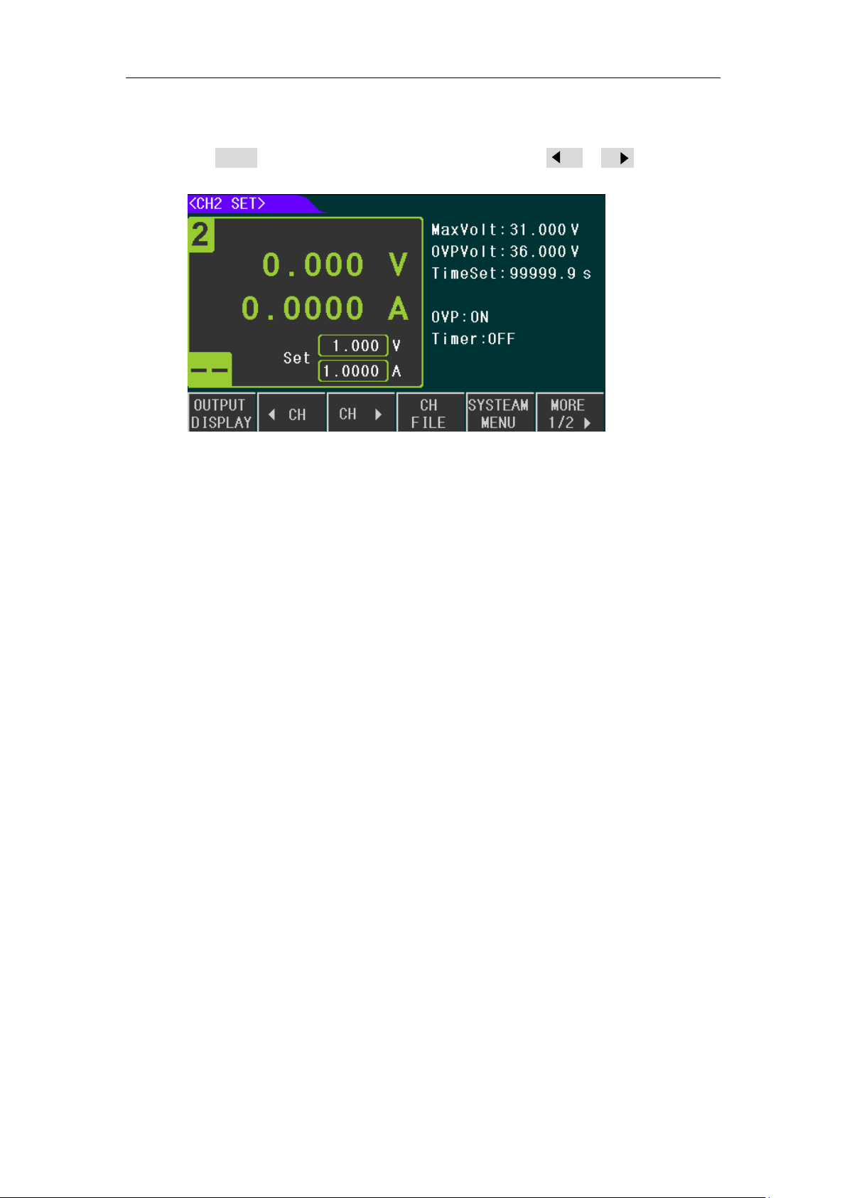
4.2 CH SET
Press CH SET to enter CH1 SET, and set another channels by CH 和CH to switch
CH2 SET is displayed as below:
On this page, you can set the parameter of one channel, the following parameter and
function can be set:
⚫Voltage, current
⚫Max Volt
⚫OVP Volt
⚫Time Set
⚫OVP
⚫Timer
⚫SAVE VALUE
4.2.1 Voltage and current Set
The setting range of voltage and current in each channel is from 0 to Max.value (The Max.
value is determined by different models).The voltage or current can be set by moving the Direction
key, and the value can set by knob or inputting the number key. Same setting as 4.1.1
4.2.2 Max. Voltage Set
The range of Max. voltage is from 0 to Max. value (which is determined by different models) When
the Max. voltage is set, the high voltage is limited. If the Max.voltage is less than the set voltage,
then set voltage can only be set to Max. Volt.
4.2.3 OVP Volt Set
The range of OVP Volt is from 0 to Max. value (which is determined by different models), same as

TH64 Series Operation Manual
9
above setting. OVP function is used to set the protective point. When the voltage is over the point
then the power supply cuts the output, meanwhile OVP is displayed.
4.2.4 Time Set
The range of time set is from 0 to 99999.9s, same as above setting. When the Time is on, the timer
starts working in the process of outputting also the count down value is displayed. When the count
down is over, then the output is closed.
4.2.5 OVP Switch
Press MORE, and enter the second picture below, press OVP to turn on or off the OVP function
4.2.6 Time Switch
Same as above setting, select the TIME to turn on or off the time function. When the Time is on
then the above picture is displayed
4.2.7 SAVE VALUE
It is used to save voltage, current, Max. Volt and OVP Volt to the File. Press SAVE VALUE to save all
settings.
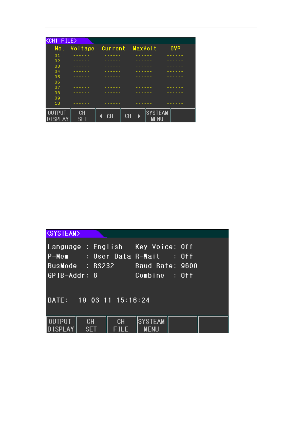
4.3 CH File
Press CH FILE to enter <CH1 FILE>. This page is used to save the voltage, current Max. voltage and
OVP voltage value in each channel. 40 groups of data can be saved, use and to
switch the channel.
TH64 Series Operation Manual
10
4.3.1 Recall and delete
There are 4 pages in CH FILE, and 10 groups of data on each page, use the direction key or PAGE
UP and PAGE DOWN to check the data.
When you want to recall some data, just use knob to select the item then click RECALL, then the
data is this group will cover the current setting. If you want to delete this group, just select DELETE.
NOTE: The data can only be saved temporary on this page, and all data will be cleared when your
turn off the device. If you want to load the saved data, please save the data into FLASH, refer to
menu set.
4.4 Menu set
Press the MENU key to enter <SYSTEM>,where you can set the working method of the tester.
The system setting is as below and you can use the direction key to select different setting.
4.4.1Language
There are 2 options
⚫中文
⚫ENGLISH

TH64 Series Operation Manual
11
4.4.2 Key voice
⚫ON
⚫OFF
4.4.3 P-Mem
The function is used to select the user data or default
⚫DEFAULT: Factory setting
⚫User Data: When there are some settings in the tester, and the settings need to be loaded when
turning on the tester next time, then you should select it. Save the setting, saved data, system
setting into Flash then you can load all data. If there is any change, please press the USER
DATA again to rewrite all data to Flash.
4.4.4 R-Wait
The tester can be back to the main display automatically after testing is on hold for a while.
⚫Off: Turn off the function
⚫5s, 30s, 60s: when the testing is on hold, and tester will be back to OUTPUT DISPLAY after a
while.
4.4.5 Bus Mode
There are 4 types of communication port.
⚫RS232
⚫GPIB
⚫USB-CDC
⚫USB-TMC
4.4.6 Baud Rate
Baud rate:
⚫4800
⚫9600
⚫19200
⚫38400
⚫57600
⚫115.2k
4.4.7 GPIB-Addr
Available for multi-set communication.
4.4.8 Combine
Set the combine status of 3 channels, and data save or recall can’t be operated in Combine status
⚫Off: Turn off Combine
⚫Series: CH1+CH2 in serial mode, when the set current is same
⚫Para: CH1+CH2 in parallel, CH2+CH3 in parallel, 3 channels in parallel, when the set voltage
is same

TH64 Series Operation Manual
12
⚫Track:CH1+CH2 in synchronous mode, CH2+CH3 in synchronous mode and 3 channels in
synchronous mode. In this mode, the set voltage and current are changed based on some ratio.
Before selecting this mode, the voltage and current must be set in advance.
E.g. set value in channels:
CH1 V:2V, I: 0.1A
CH2 V:1V, I: 0.3A
Then select CH1+CH2 TRACK
After selecting this mode, if any set value in some channel is changed
Like: CH1 V:3V, I:0.2A, now the set value in another channel is changed to CH2 V:1.5V.
I: 0.6A.
If the set voltage/current is 0 before selecting the TRACK, then the track is failed
4.4.9 Date
There is RTC clock, which can realize the real time display, move the cursor to this item and press
SET, then you can set the year, month, date, hour, minute, and second

TH64 Series Operation Manual
13
Chapter 5 Operation
(1) Connect to power and press power switch
(2) Warm up 20 min
(3) According to the actual requirement, select the suitable connection cable, connect the load to
the [+,-] terminal in the tester. In Combine mode, the connection cable in the output terminal
must be connected in serial or parallel. Same way is used when rear panel is used
(4) When setting the working mode and output parameter, the output channel must be selected,
press the corresponding CH key to output or press ON/OFF for 3 channels output
simultaneously

TH64 Series Operation Manual
14
Chapter 6 Interface and communication
RS232C, GPIB and USB are available in this tester, which can be used for data communication and
remote control but not at the same time. The command is same for all ports, but the hardware
configuration and communication protocol is different. Please refer to Chapter 6.2 for more details.
6.1 Remote Control
6.1.1 RS232 description
The provided RS232 interface can be used to communicate with PC, which can provide multiple
commands. All operation on the front panel of tester can be realized via RS232
6.1.1.1 Introduction of RS232 interface
RS-232 standard, also called as asynchronous serial communication standard, has already been
widely used for data communication between computers, computer and external equipment. RS is
the English abbreviation of Recommended Standard; 232, the standard number. This standard is
issued by EIA in 1969, which rules to send one bit in a data line every time.
As most serial interfaces, the serial interface of TH64 Series is also not strictly based on RS-232
standard but only uses the smallest subset of this standard. The signals are listed in the following
table.
The reason is that the use of three lines is much more inexpensive and much simpler than that of
five lines or six lines, which is the biggest advantage of using serial interface for communication.
Note: The pin definition of this tester is same as the standard 9-core connector
The 9-core DB type socket of RS232C in this tester is as below:
The standard 9-core DB type plug can be used directly
!
Warning: Power supply must be cut when connecting and disconnecting the connector to
avoid the electrical shock.
!
Warning: Not short the output terminal, or with body to avoid the components being
burnt.
Signal
Code
Connector Pin Number
Transmitted Data
TXD
3
Received Data
RXD
2
Signal Ground Common
GND
5
1 2 3 4 5
6 7 8 9

TH64 Series Operation Manual
15
6.1.1.2 Communicate with PC
The connection of tester to PC is displayed as below:
Based on the table above, the pin definition of this tester is same as the 9-core connector of IMB AT.
User can make 3 wore connection cable (length is less than 1.5m) by using double core shielding
wire or buy from us.
When user makes own cable, please note that, Pin4, 6, Pin7 and 8 must be shorted in PC interface.
Please set the bus mode, select RS232 in SYSTEM.
Main parameter
Transmission
mode
Full duplex asynchronous communication
including start and stop bit
Baud rate
9600 bps
Data bit
8 BIT
Stop bit
1 BIT
Verification
None
End symbol
NL(line break,ASCII code 10)
Contact
software
Connector
DB9 core
6.1.2 GPIB interface
6.1.2.1 GPIB bus
IEEE488 (GPIB) is an international bus interface standard used on intelligent instruments. IEEE is
the English abbreviation of Institute of Electrical and Electronics Engineers, and 488 is the standard
number. Through this interface, this tester can communicate with PC or others intelligent devices
and meanwhile can make up automatic test system with the other devices. Up to 15 devices can
be connected on a same bus. This tester applies IEEE488.2 and the interface plate can be inserted
in any one of the three expansion slots Control command system is open so that user can use the
PC operation interface provided by this tester or take measurements by the control command
system. The control command system supports most functions of the instrument, that is to say,
user can execute almost all operations on PC. Thus remote control to the instrument is realized.
When configuring a GPIB system, the following restrictions must be adhered to.
1.The total length of cable in one bus system must be less than or equal to two meters times

TH64 Series Operation Manual
16
the number of devices connected on the bus (the GPIB controller counts as one device)
and the total length of cable must not exceed 20 meters.
2.A maximum of 15 devices can be connected on one bus system.
3.There are no restrictions on how the cables are connected together. However, it is
recommended that no more than four piggyback connectors be stacked together on any
one device.
Way 1
Table of contents
Popular Power Supply manuals by other brands


Puls
Puls dimension UB10.241 instruction manual

Altronix
Altronix ALTV615DC44ULM installation guide

Eaton
Eaton PSG120E installation instructions

Whelen Engineering Company
Whelen Engineering Company ISP8HS installation guide

WAGO
WAGO EPSITRON-PRO-Power instruction manual

Schaffner
Schaffner Ecosine active sync User and installation manual