FEAS SNT125-BL User manual

Betriebsanleitung
Bitte sorgfältig beachten!
Operating
instructions
Please observe carefully!
SNT125-BL
SNT12512-BL
Für die Modelle:
- konform
GmbH
Postfach 1521
D - 22905 AHRENSBURG
Telefon: 04102 - 42082
Telefax: 04102 - 40930
www.feas.de
®
For the types:
©2020
Schutzeinrichtungen
bei 115 VAC 10A träge / bei 230 VAC 5A träge
nicht erforderlich, da kurzschlussfest
im Gerät integriert
Ausgangssicherung
Überlastschutz
Eingangsgrößen
85 - 270V ( - 66Hz)44
AC
bei 115VAC max. 5,0A /bei 230VAC max. 2,5A
<8,2 A bei 270VAC
Transientenüberspannungsschutz-Varistor
Eingangswechselspannung
Stromaufnahme bei Nennlast
Einschaltstromstoß
Schutzbeschaltung
Betriebsdaten
100% (Dauerbetrieb)
-40°C bis +80°C
Einschaltdauer (ED)
Arbeitstemperaturbereich
-40°C bis +105°C
Ja
ab 40°C
Lagertemperaturbereich
Parallelschaltbar
Leistungsabweichung bei Temperatur
natürliche KonvektionKühlung
Wirkungsgrad siehe Tabelle unten
Aufstellungshöhe
MTBF
unbegrenzt
> 380.000h
Ausgangsgrößen
siehe Tabelle unten
siehe Tabelle unten
Ausgangsspannung U
Ausgangsstrom I
Leistung
Restwelligkeit (20MHz Bandbreite)
siehe Tabelle unten
<50mVrms
Technische Daten
Angewandte Bauvorschriften
CSA/UL CSA-C 22.2 / Ul60950, Ul508, UL1950
gemäß VDE
IEC
EN
VDE0100, VDE0110, VDE0113, VDE0551,
VDE0806
IEC60950-1, IEC61000-6-1,2,3,4, IEC60068-2-3,
EN60950-1, EN61140, EN61000-6-1, EN61000-6-2,
EN61000-6-3, EN61000-6-4, EN55022, EN55011
EN61000-3-2, EN61000-3-3, EN60204
EN60529, EN61000-4-2-3-4-5-6-8-11, EN60068-1,
EN6068-2-1, EN61558-2-17
IEC60068-2-11-52, IEC60529
Sicherheitsdaten
Prüfspannung Trafo 5kV gemäß VDE0570
AC
Hochspannungsfestigkeit Eingang/Ausgang 4,4kV nach VDE0806/IEC380
AC
Funkentstörgrad gemäß VDE0871B, EN55022/B
95% relative Feuchte im Jahresdurchschnitt
Betauung möglich - tropentauglich
Schutzklasse
Umgebungsfeuchte
Schutzart Gehäuse mit Steckern
Schutzklasse I mit PE-Anschluss (EN60950)
Rüttelfestigkeit >100g bei 33Hz in X, Y und Z
nach IEC68 und DIN41640
Schutzkleinspannung PELV (EN60204), SELV (EN60950)
IP 68
Safety devices
at 115 VAC 10A delayed / at 230 VAC 5A delayed
not necessary - short circuit proof
integrated into device
Fuse for output
Overload protection
Input data
85 - 270V (44 - 66Hz)
AC
at 115VAC max. 5.0A / at 230VAC max. 2.5A
< 8.2 A at 270VAC
Transient voltage suppressor Varistor
AC input voltage
Input current at nominal load
Input current peak
Protective circuit
Operating data
100%
-40°C to +80°C
Duty circle
Operating temperature range
-40°C to +105°C
Yes
from 40°C
Storage temperature range
Parallel connection
Derating
selfcoolingCooling
Efficiency see table below
Installation altitude
MTBF
unlimited
> 380.000h
Output data
see table below
see table below
Output voltage U
Output current I
Power
Residual ripple (20MHz Bandwidth)
see table below
<50mVrms
Technical Data
Applied construction regulations
CSA/UL
according to VDE
IEC
EN
CSA-C 22.2 / Ul60950, Ul508, UL1950
VDE0100, VDE0110, VDE0113, VDE0551,
VDE0806
IEC60950-1, IEC61000-6-1,2,3,4, IEC60068-2-3,
EN60950-1, EN61140, EN61000-6-1, EN61000-6-2,
EN61000-6-3, EN61000-6-4, EN55022, EN55011
EN61000-3-2, EN61000-3-3, EN60204
EN60529, EN61000-4-2-3-4-5-6-8-11, EN60068-1,
EN6068-2-1, EN61558-2-17
IEC60068-2-11-52, IEC60529
Safety data
Test voltage transformer 5kV according to VDE0570
AC
High voltage resistance Input/Output 4,4kV according to VDE0806/IEC380
AC
Degree of EMI suppresion according to VDE0871B, EN55022/B
95% relative humidity, yearly average
dewing allowed for use in tropical ambient
Protection class
Ambient humidity
Protective class enclosure with plugs
Protection class I with PE-Connection (EN60950)
Vibration proof >100g at 33Hz in X, Y and Z
acc. IEC68 and DIN41640
Extra low safety potential PELV (EN60204), SELV (EN60950)
IP 68
Vorsicherung (techn. nicht erforderlich) Fuse for input (technically not necessary)
Verbraucher (z.B. Schütze, Motoren, Magnetventile,
etc.) die nicht ordnungsgemäß nach den relevanten
Richtlinien entstört sind (z.B. Varistoren, RC-Glieder,
etc), können zur Störung bzw. Zerstörung des
Netzgerätes führen.
Consumers (e.g. contactors, motors, solenoid valves
etc.) which have not been correctly interference-
suppressed in accordance to the relevant guidelines
(e.g. varistors, RC elements, etc.) may cause power
supply regulation to malfunction.
Typ
Ausgangsleistung
Output-power
SNT12512-BL
25,0A
355 Watt
91%
Ausgangsstrom I
Output current I
Wirkungsgrad
Efficiency
Maße
Dimensions
Gewicht
Weight ca. 7,50kg
BxHxT
BxHxD 171mm x 213mm x 103mm
Vorsicherung
Fuse for input
bei 115VAC 10,0Amp. träge / bei 230VAC 5,0Amp. träge
at 115VAC 10.0Amp. delayed / at 230VAC 5.0Amp. delayed
Ausgangsspannung U
Output voltage U14,2VDC fest eingestellt für 12V Akkus
fixed value for 12V batteries
Anschlüsse
SCHUKO-Stecker mit Schutzkappe
Hirschmann-Buchse mit 1m Kabel (4x1,5mm²)
(andere Kabellängen auf Anfrage möglich)
Ausgang
Connections
SCHUKO plug with protective cap
Hirschmann socket with 1m cable (4x1.5mm²)
(other cable lengths possible on request)
Output
Eingang Input
1. Funktionsweise
Das SNT125-BL ist ein Schaltnetzteil zur Speisung von
Verbrauchern aus dem Niederspannungsnetz. Die Kühlung
erfolgt über Luftkonvektion am Gehäuse-Kühlprofil. Bitte die
“Derating-Kurve” beachten.
1. Mode of operation
The SNT125-BL is a power supply to supply consumers from
low voltage network.The cooling of the device takes place via
air convection at the case heatsink. Please observe the
derating.
2. Montage
Das SNT125-BL kann mit vier M8-Schrauben lageunabhängig
auch an beweglichen Maschinen montiert werden. SNT125-BL
ist rüttelfest.
Bitte die Bohrmaße auf der letzten Seite beachten.
2. Installation
The SNT125-BL can be mounted with four M8 screws in any
position - also on moving machines. SNT125-BL is vibration-
proof.
Take notice of the drilling dimensions on the last page.
3. Elektrischer Anschluss
Das Gerät laut Anschluss-Schema unten anschließen. Hierbei
unbedingt die allgemeinen Sicherheitsvorschriften beachten.
Unsachgemäßer Anschluss kann zu einem Defekt des Gerätes
führen.
3. Electrical connection
Take care of a correct electrical connection. Take the wiring
diagram at the bottom of this side as help. Inappropriate
connection can lead to a defect of the device.
5. Allgemeine Sicherheitsvorschriften
Beim Umgang mit Produkten, die mit elektrischen Spannungen in
Berührung kommen, müssen die gültigen VDE / IEC / EN Vorschriften
beachtet werden. Besonders sei auf folgende Vorschriften
hingewiesen: VDE 0100, VDE 0550 / 0551, VDE 0711, VDE 0860,
IEC 664, IEC 742, IEC 570, IEC 65
Bei Nichtbeachtung der Bedienungsanleitung oder der Anschluss-
vorschrift, z.B. bei Vertauschen der Anschlussklemmen, kann das
Gerät oder die Anlage beschädigt werden und der Betreiber verliert
seinen möglichen Haftungsanspruch.
Durch den vollständigen Verguss darf das Gerät nicht geöffnet
werden, andernfalls erlöschen jeglicher Garantie- und Haftungs-
anpruch.
Werkzeuge dürfen an Geräten, Bauteilen oder Baugruppen nur
benutzt werden, wenn sichergestellt ist, dass die Geräte von der
Versorgungsspannung getrennt sind und interne elektrische Bauteile
entladen sind.
Vor dem Öffnen des Gerätes den Netzstecker ziehen und
sicherstellen, dass das Gerät spannungslos ist und bleibt. Bauteile,
Baugruppen oder Geräte dürfen nur in Betrieb genommen werden,
wenn sie vorher in ein berührungssicheres Gehäuse eingebaut
wurden. Während des Einbaus müssen sie stromlos sein.
Spannungsführende Kabel oder Leitungen, mit denen das Gerät, das
Bauteil oder die Baugruppe verbunden sind, müssen stets auf
Isolationsfehler oder Bruchstellen untersucht werden. Bei Feststellen
eines Fehlers in der Zuleitung muß das Gerät unverzüglich aus dem
Verkehr genommen werden, bis die defekte Leitungen ausgewechselt
worden sind.
Der Anwender hat dafür Sorge zu tragen, dass die angegebenen
Gerätedaten nicht überschritten werden.
Wenn aus den vorgelegten Beschreibungen für den Anwender oder
Erwerber nicht eindeutig hervorgeht, welche Kennwerte für ein Gerät
oder Bauteil gelten, so muss stets ein Fachmann um Auskunft ersucht
werden.
Im Übrigen unterliegt die Einhaltung von Bau- und Sicherheits-
vorschriften aller Art ( VDE, TÜV, Berufsgenossenschaften) dem
Anwender / Käufer.
5.General safety rules
When working with products which are in contact to dangerous
electrical voltages, attention must be payed to the relevant valid VDE /
IEC / EN regulations. Especialy with refrence to the following rules:
VDE 0100, VDE 0550 / 0551, VDE 0711, VDE 0860, IEC 664, IEC
742, IEC 570, IEC 65
In case of non-observance of this instructions the unit or other
equipment might be damaged and no warranty or liability could be
accepted.
The device must not be opened as a result of complete potting,
otherwise all warranty and liability claims will lapse.
When it is necessary to use tools on the device components parts or
subassemblies make sure that the power is disconnected from the
device and all capacities are discharged.
Before opening the equipment disconnect the power cord and make
sure that the contacts are not energized. It is only allowed to take
components parts, subassemblies or device into operation if they are
mounted in an insulated housing. During the installation all devices
have to be disconnected from power sources.
Power cords and leads which are connected to the device,
components or subassemblies have to be inspected for damaged
insulation. If a failure is detected the device or the subassembly has
to be put out of service at once. It is not allowed to take the device or
the subassembly into operation before replacing the damaged power
cord.
It is up to the user’s responsibility that the specification limits of the
device are not exeeded.
If the user is not fully able to relate the technical guidelines, a
technical adviser has to be asked for information.
The observance of construction requirements and safety rules (VDE,
IEC, employers liability insurenance i.e.) is subject to the
user/customer.
Aufgrund der internen Transienten-
Schutzschaltung darf die Isolationsprüfung
Ihrer Anlage nicht mit unserem Gerät erfolgen.
Due to the internal transient protection circuit,
the insulation test of your system must not be
carried out with our device.
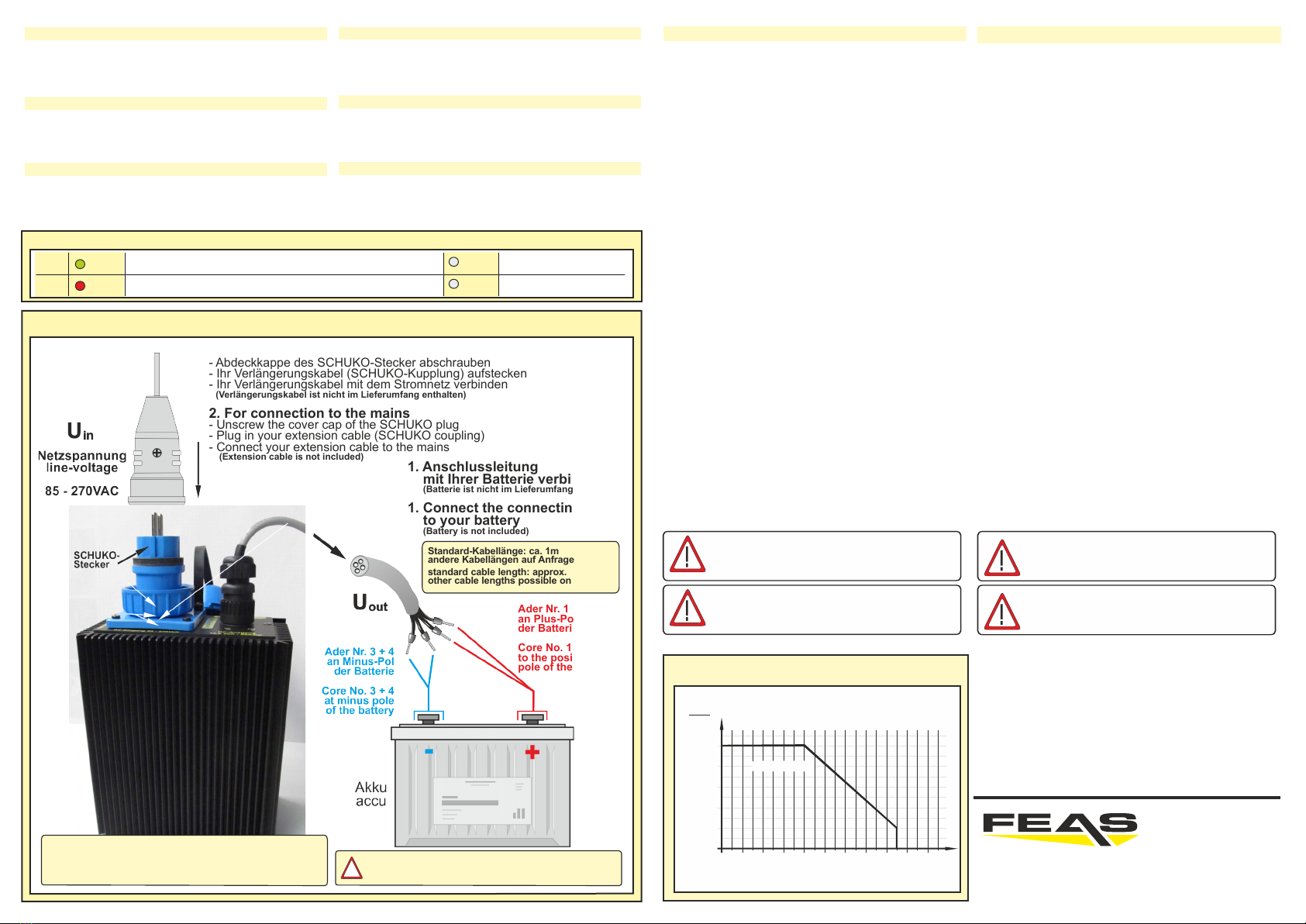
Anschlussschema / Wiring diagram
Derating ab 40°C / derating from 40°C
Ader Nr. 1 + 2
an Plus-Pol
der Batterie
Core No. 1 + 2
to the positive
pole of the battery
1. Anschlussleitung
mit Ihrer Batterie verbinden
(Batterie ist nicht im Lieferumfang enthalten)
1. Connect the connecting cable
to your battery
(Battery is not included)
2. Zum Anschluss an das Stromnetz
- Abdeckkappe des SCHUKO-Stecker abschrauben
- Ihr Verlängerungskabel (SCHUKO-Kupplung) aufstecken
- Ihr Verlängerungskabel mit dem Stromnetz verbinden
(Verlängerungskabel ist nicht im Lieferumfang enthalten)
2. For connection to the mains
- Unscrew the cover cap of the SCHUKO plug
- Plug in your extension cable (SCHUKO coupling)
- Connect your extension cable to the mains
(Extension cable is not included)
standard cable length: approx. 1m
other cable lengths possible on request
Standard-Kabellänge: ca. 1m
andere Kabellängen auf Anfrage möglich
0,4
0,2
0
0,6
1,0
20100 30 50 70 90 10040 60 80
0,8
T / C°
Temperatur / temperature in °C
Iout
Inenn
Dauerbetrieb
Ausgangsstrom
Output current
Zur besseren Wärmeabfuhr sollte das Gerät
einen Mindestabstand von 15mm zu anderen
Geräten haben.
For better cooling, the devices should have a
minimum distance of 15mm to other
appliances.
Störung durch Kurzschluss, Übertemperatur oder Überlast
Fault due to short circuit, overtemperature or overload
keine Eingangsspannung
No Input
Normalbetrieb
Normal operation
Netz vorhanden / Gerät betriebsbereit
Input OK / device ready for use
ON
Fail
green
red
off
off
LED-Anzeigen / LED displays
!
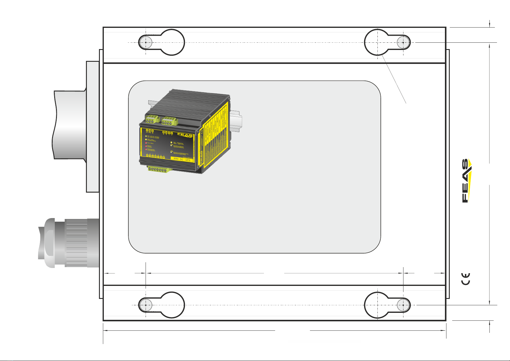
Montageposition lageunabhängig
Bohrmaße siehe letzte Seite
mounting position independent of position
drilling dimension see on last page
GmbH
Postfach 1521
D - 22905 AHRENSBURG
Telefon: 04102 - 42082
Telefax: 04102 - 40930
www.feas.de
©2020
Nur Akkus oder wiederaufladbare Batterien laden!
Only charge accumulators or rechargeable batteries!
150,0
200 mm
153,0
9,0 9,0
25,0
Geeignet für M8 Schrauben
Suitable for M8 screws
25,0
- konform GmbH
Postfach 1521
D - 22905 AHRENSBURG
Telefon: 04102 - 42082
Telefax: 04102 - 40930
www.feas.de
©2020 ®
Maße Rückseite - Dimensions backside
LDR30MH24
Mini DC-USV für die Hutschiene
Art.Nr.: 589960
Ÿ3 in 1, vereint Schaltnetzteil, Ladekontrolleinheit und Akku in
einem sehr kompakten Gehäuse
ŸPufferung eines Verbrauchers bei Netzausfall
ŸPufferzeit begrenzbar (1-20 Minuten und unbegrenzt)
ŸIm Pufferbetrieb manuell abschaltbar, “Schlafenlegen”
ŸIntegrierter NiMH Akkumulator mit 0,72 Ah (austauschbar)
ŸMikroprozessorgesteuerte Akkumulator-Überwachung und
Ladeanzeige
ŸLED-Anzeigen für Netzausfall, Überlast und Übertemperatur,
Akku laden, Akku Alarm, Pufferbetrieb
ŸRelais-Meldung von Netzausfall, Akku-Defekt, Übertemperatur
und Akkuspannung kritisch
ŸBoostfunktion: 150% Iout über längeren Zeitraum möglich
ŸKurzschlussfest, überlast- und leerlaufsicher
ŸAusgang potentialfrei nach VDE 0551
Technische Daten:
Eingang: 85-270 VAC (44-66 Hz) / 120-380 VDC
Ausgangsspannung: 24 VDC (22,5 VDC - 29,5 VDC)
Ausgangsstrom: 2,0 A (3,0 A Boost)
Kapazität: 0,72 Ah
Leistung: 48,0 Watt
Wirkungsgrad: ca. 91%
Restwelligkeit: < 50 mVrms
Arbeitstemperatur: -20°C / +70°C
Montage: auf Hutschiene nach DIN 46277
Abmaße (BxHxT): 108,0 x 100,0 x 120,0 mm
Gewicht: 2,30 kg
This manual suits for next models
1
Other FEAS Power Supply manuals


Popular Power Supply manuals by other brands


Manson Engineering Industrial
Manson Engineering Industrial ZPS-9160 Operation manual

Whelen Engineering Company
Whelen Engineering Company CS650 installation guide

urmet domus
urmet domus SLAVE 1722 Installation handbook

Delta Electronics
Delta Electronics SMT Power Inductor MPO13X Product specifications

Akyga
Akyga AK-ND-55 user manual

Bosch
Bosch Rexroth VM350 manual