ITW Simco-Ion Dual Phase+ User manual

Dual Phase+ Power Supply 5100636 Rev. F
Dual Phase+ Power Supply
INSTALLATION AND OPERATING INSTRUCTIONS

i
Dual Phase+ Power Supply 5100636 Rev. F
TABLE OF CONTENTS
1. SAFETY WARNINGS.......................................................................................................................1
2. DESCRIPTION...............................................................................................................................2
3. SPECIFICATIONS...........................................................................................................................2
4. INSTALLATION .............................................................................................................................2
Mounting and Grounding .....................................................................................................3
High Voltage Connections .....................................................................................................4
AC Line Power (Low Voltage) Connections...........................................................................5
Warning / Fault Conditions...................................................................................................5
Remote Interface....................................................................................................................6
Remote Interface Box (Option) .............................................................................................7
5. OPERATION .................................................................................................................................8
6. TROUBLESHOOTING......................................................................................................................9
7. MAINTENANCE.............................................................................................................................9
8. WARRANTY .................................................................................................................................9

1
Dual Phase+ Power Supply 5100636 Rev. F
1. SAFETY WARNINGS
NOTE
– Statements Identified with a NOTE indicate precautions necessary
to avoid potential equipment failure.
CAUTION
– Statements identified with a CAUTION indicate potential
safety hazards.
1. This equipment must be correctly installed and properly maintained. Adhere
to the following cautions for safe installation and operation.
2. Read instruction manual before operating or installing device.
3. Qualified service personnel must do installation and repairs.
4. Ground the frame of the machine on which the power supply and neutralizing
bars are mounted.
5. Disconnect supply voltage to power supply before connecting neutralizing bar
to the high voltage terminal strip.
CAUTION
– Electrical Shock Hazard
Do not touch bar when power supply is energized.
Disconnect supply voltage to power supply before connecting bar or
performing any maintenance to the system.
CAUTION
– Fire Hazard
Do not install or operate neutralizing bar in close proximity to any
flammable solvents.

2
Dual Phase+ Power Supply 5100636 Rev. F
2. DESCRIPTION
Simco-Ion’s Dual Phase+ Power Supply is designed to power Simco-Ion’s
Conveyostat and High Speed Web Bar Static Neutralizers. The Dual Phase+ Power
Supply is capable of producing bipolar high voltage currents used to generate both
positive and negative ions in extremely high quantities. This allows the neutralization
of static charges on products moving at high speeds.
3. SPECIFICATIONS
Input Voltage 120 VAC, 60 Hz, 0.5A
230 VAC, 60 Hz, 0.25A
Output Voltages 120 (4 kV), 4016574 NEMA 12 Enclosure (indoor Conveyostat)
120 (4 kV), 4016576 NEMA 4 Enclosure (outdoor Conveyostat)
230 (4 kV), 4016575 NEMA 12 Enclosure (indoor Conveyostat)
230 (4 kV), 4016577 NEMA 4 Enclosure (outdoor Conveyostat)
Short Circuit Current 5.0 mA (max)
Enclosure Painted steel with hinged and gasketed cover
Weight 22 lb (approx)
Color Grey cabinet; white panel
4. INSTALLATION
Before placing the static neutralizer and the Dual Phase+ Power Supply in operation,
be sure that all grounds and connections have been made as described in the
following steps. Turn the power OFF when the equipment is not in use.
a. The power unit supplied is selected by the factory depending on the type of
static neutralizer to be powered. Therefore the power unit must be used only
with the unit for which it was originally supplied. Do not remove equipment
from, or add equipment to, the power unit without first consulting Simco-Ion.
b. A typical power unit consists of two transformers (Phase A and Phase B) housed
in an industrial NEMA Type 12/13 enclosure (see Figure-1). Connections to
the transformer primary windings are alternated so that a pair of transformers
will produce both polarities simultaneously at the outputs. This means that
both positive and negative ions are produced at the same time by adjacent static
bars within the static neutralizer.
c. Power requirements for Dual Phase+ Power Supplies: 120 VAC, 60 Hz, approx
1 Amp.

3
Dual Phase+ Power Supply 5100636 Rev. F
Mounting and Grounding
CAUTION
– Failure to properly ground the power unit may result in electrical
shock hazard to personnel and inefficient operation of the static neutralizer.
1. Mount the power unit to the machine frame or to a convenient wall or post.
Mount the power unit to a flat surface using the mounting flanges at the base
of the power unit. Be sure to position it so that the power unit’s case is properly
grounded in order to ensure safe and efficient operation of the static neutralizer.
2. Ground the Dual Phase+ Power Supply by the following method: When
installing the AC line power wiring, use 3-conductor cable. Two conductors
will supply the line voltage. The third conductor will provide the ground
connection between the ground at the power source (junction box or panel)
and the ground post on the inner side of the wiring compartment of the power
unit’s case.
Figure 1. Dual Phase+ Enclosure

4
Dual Phase+ Power Supply 5100636 Rev. F
Figure 2. HighVoltage Wiring to Static Neutralizer
SIMCO-ION
Figure 3. Low Voltage Wiring to Electrical Supply
High Voltage Connections
1. Make certain the power is OFF.
2. Open the door to the Power Unit.
3. Feed the high voltage cables through the grey bushings on the bottom side of
the box (see Figures 2&3 above).

5
Dual Phase+ Power Supply 5100636 Rev. F
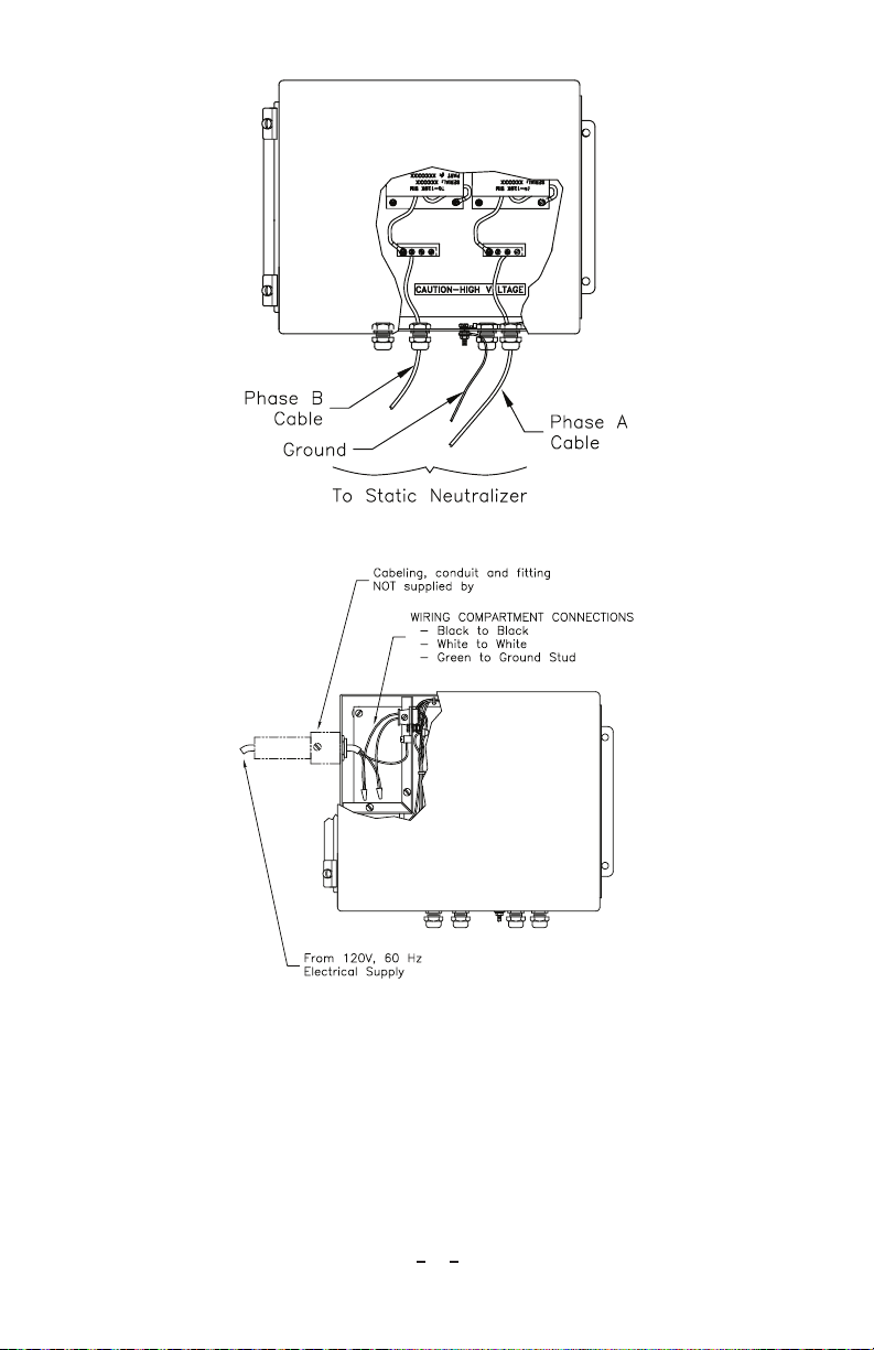
4. Cut the high voltage cable to the desired length. Be sure to allow additional
length to reach the high voltage output terminal blocks inside the power unit’s
case.
5. Strip 3/8” insulation from the end of the high voltage cable and insert the cable
through a straight-through fitting.
6. Loosen one of the connection screws on the high voltage output terminal block.
Insert the stripped end of the cable under the screw and tighten. Tighten the
straight-through fitting until snug. Pull gently on the cable to make certain the
connection is secure.
AC Line Power (Low Voltage) Connections
CAUTION
–
Do not apply line voltage to the Power Unit until all grounds
and high voltage connections have been completed and the static neutralizer
has been installed.
1. Connection should be made only to a 3-wire 120V, 60 Hz AC source.
2. For rigid cable connection to the power unit: the use of local code approved
solid 3-conductor cable through ½” size conduit with approved fittings is
recommended (not supplied). On installations subject to Canadian Standards
Approval: the use of conduit is required.
3. For flexible connection to power unit: the use of local code approved
3-conductor line cord is recommended (not supplied). Secure line cord to
power unit with an approved cable clamp.
4. Connect the power source to the black and white leads using proper size wire
nuts. Connect the grounded conductor to the ground post.
NOTE
–
If the static neutralizer is to be used on machinery, it is recommended
that the power unit’s input wiring be connected to the machine’s RUN
button. This will enable the power unit to be turned ON and OFF with the
machine.
Warning / Fault Conditions
The Dual Phase+ generates warning and fault conditions based on the operational
conditions of connected hardware. Warning conditions indicate that material
(typically metalized film) is congesting the connected Conveyostat and impeding
the output of one or more ionizer bars. The Warning condition is indicated by a
yellow light. It is normal that the warning condition may be intermittent. Even
with the Warning indicated, the Dual Phase+ continues to produce ionization in
the Conveyostat system. If the Warning is indicated continuously, service should be
scheduled to remove material trapped in the Conveyostat.

6
Dual Phase+ Power Supply 5100636 Rev. F
The Dual Phase+ indicates a fault condition with a flashing red light. The flashing
red light indicates that a hard arc has been detected by the system. For safety the
high voltage generators of the Dual Phase+ are shut down under this condition.
To correct this condition it is required to inspect the connected Conveyostat for
wiring faults or other short circuit conditions in the high voltage wiring. The fault
condition can be cleared by cycling power or depressing the reset button on the
front of the unit.
Remote Interface
Figure 4. Remote Interface Pinouts
The Dual Phase+ includes a 12 position connector that allows the user to remotely
interface to the unit. The remote interface provides relay contacts reflecting the
conditions of power, warning and fault. The remote interface also has an on/off
input allowing the unit to be switched on/off remotely.
The remote on/ off input of the Dual Phase+ requires on 24 VDC. Application of 24
VDC to the remote on/off pins of the interface turns the unit on. Note that cycling
power to the unit through this interface can also be used to reset a fault condition.
To use the remote on/off feature the front panel switch of the unit must be in the
off position.
The Power state of the Dual Phase+ is indicated on Power Relay pins of the remote
interface. When the unit is powered the state of the power relay changes and it is
held in this state. This allows detection of AC power loss to the Dual Phase+, as well
as an off condition.

7
Dual Phase+ Power Supply 5100636 Rev. F
The Warning state of the Dual Phase+ is indicated on the Warning pins of the
remote interface. The relay contacts change with the illumination of the Yellow
warning light on the front of the unit. It is normal for the warning condition
to be intermitted, if the warning indication is continuous servicing the connect
Conveyostat should be completed. Typically with warning light indicates that ion
generation of one or more bars is impeded by debris.
The Fault state of the Dual Phase+ is indicated on the Fault pin of the remote
interface.
The relay contacts change state with the illumination of the Red fault light on the
front of the unit. In a fault condition the red light flashes, relay contacts for fault
toggle accordingly. In this case ionization is shut down for safety, the installation
should be checked for high voltage wiring faults or other conditions that would
create an high voltage arc.
NOTE
–
Wiring to the remote interface connector should be routed clear of
the high voltage generators internal to the Dual Phase+.
Remote Interface Box (Option)
Figure 5a. Remote Interface Box Wiring Diagram

8
Dual Phase+ Power Supply 5100636 Rev. F
Figure 5b. Remote Interface Wiring Connections
An optional remote box is available. This box interfaces to the remote interface of
the dual phase and allows the unit to be powered and monitored remotely. This can
be beneficial to the installation by allowing the Dual Phase+ to be located close to
the Conveyostat thereby shortening the required high voltage wiring to a minimum.
The remote interface box incorporate an on/off switch used to remotely turn the
Dual Phase+ on/off and includes LED indicators for Power, Warning and Fault
conditions. The remote box should be used in conjunction with the 24 VDC power
source supplied.
5. OPERATION
1. Before operating the equipment, make certain all grounds and connections have
been made as described in Section 2. Make certain the static neutralizer has also
been properly installed.
2. To begin operating the equipment, simply apply line power to the Power
Supply. The green light indicates power to the unit.
3. Always turn the power OFF when the equipment is not in use.
4. A “Check System” warning indicator is located on the face of the Power Supply.
Loss of high voltage, or a short circuit within the attached static neutralizing
device or its cables, will disable the Power Supply’s high voltage output and
cause the red indicator to flash.
5. To reset a fault condition and extinguish the flashing “Check System” indicator,
you must first remedy the cause of the fault. Then simply press and hold the
RESET button until normal operation is resumed.

9
Dual Phase+ Power Supply 5100636 Rev. F
6. TROUBLESHOOTING
1. For safety and proper operation, Simco-Ion’s static neutralizers must be
connected to Simco-Ion power supplies as supplied by the factory to operate.
Standard line voltage is converted to an output of approximately 4000 volts
AC. In the event of a direct short circuit to ground at the output of power, the
output current is limited to a maximum of 5 mA.
2. Precautions must be taken to avoid contacting the output of the Power Supply,
the inner conductor of the high voltage cable, and the emitter points of the
Simco-Ion Static Neutralizer. These points must be shielded and interlocked
to prevent personnel contact with high voltages. Failure to do so may result in
danger of electrical shock to personnel.
7. MAINTENANCE
Occasionally check to make certain that all ground and electrical connections are
clean and tight. Periodically inspect all cables and wiring to ensure that there are
no cuts, abrasions, or damage that can lead to operator shock or equipment damage.
8. WARRANTY
This product has been carefully tested at the factory and is warranted to be free
from any defects in materials or workmanship. Simco-Ion will, under this warranty,
repair or replace any equipment that proves, upon our examination, to have become
defective within one year from the date of purchase.
The equipment being returned under warranty should be shipped by the purchaser
to Simco-Ion, 2257 North Penn Road, Hatfield PA 19440, transportation prepaid
and insured for its replacement cost. Prior to returning any goods for any reason,
contact Simco-Ion Customer Service at (215) 822-6401 for a Return Authorization
Number. This number must accompany all returned items.
This warranty does not apply when the equipment has been tampered with, misused,
improperly installed, altered, has received damage through abuse, carelessness,
accident, connected to improper line voltage, or has been serviced anyone other than
an authorized factory representative.
The warranty does not apply when Simco-Ion parts and equipment have been
energized by other than the appropriate Simco-Ion power supply or generator,
or when a Simco-Ion power supply or generator has been used to energize other
than Simco-Ion parts and equipment. Simco-Ion makes no warranty, expressed or
implied, nor accepts any obligation, liabilities, or responsibility in connection with
the use of this product other than the repair or replacement of parts stated herein.

Dual Phase+ Power Supply 5100636 Rev. F
Simco-Ion
2257 North Penn Road
Hatfield, PA 19440
(215) 822-6401
(800) 203-3419
www.simco-ion.com
© 2020 Simco-Ion. Printed in the U.S.A.
Table of contents
Other ITW Power Supply manuals

ITW
ITW SIMCO ION D Series User manual

ITW
ITW Simco-Ion S165S User manual

ITW
ITW Orbitalum ORBIMAT 165 CA User manual

ITW
ITW SIMCO ION IQ Power BPS-C User manual

ITW
ITW Simco-Ion Chargemaster VCM30 Series User manual

ITW
ITW Simco-Ion IQ Power HL User manual

ITW
ITW Simco-Ion Chargemaster Pinner Superbar User manual

ITW
ITW Simco-ion IQ Power MPS User manual

ITW
ITW Simco-Ion D167Q User manual