Tonghui Electronics TH9110 User manual


◇2
Content
Chapter 1 Overview....................................................................................................................................4
1.1 Introduction .........................................................................................................................................................4
1.2 Conditions of Use................................................................................................................................................5
1.2.1 Power............................................................................................................................................................................5
1.2.2 Ambient Temperature and Humidity......................................................................................................................................5
1.2.3 Preheating..........................................................................................................................................................................5
1.2.4 Precautions ........................................................................................................................................................................5
1.3 Volume and Weight.............................................................................................................................................6
1.4 Safety Requirements............................................................................................................................................6
1.4.1 Insulation Resistance...........................................................................................................................................................6
1.4.2 Insulation Strength..............................................................................................................................................................6
1.4.3 Leakage Current .................................................................................................................................................................6
1.5 Electromagnetic Compatibility............................................................................................................................7
Chapter 2 Precautions on Handling..........................................................................................................8
2.1 Operation Standards......................................................................................................................................8
2.2 Handling Meansures ...................................................................................................................................10
Chapter 3 Panel Description....................................................................................................................12
3.1 Front Panel ........................................................................................................................................................12
3.2 Rear Panel..........................................................................................................................................................13
Chapter 4 Basic operation........................................................................................................................15
4.1 Interface structure overview..............................................................................................................................15
4.2 SYSTEM Setup.................................................................................................................................................16
4.2.1 System Test Parameter Settings...........................................................................................................................................16
4.2.2 System Environment Parameters Setting..............................................................................................................................21
4.2.3 System Communication Setup ............................................................................................................................................23
4.3 Meas SETUP.....................................................................................................................................................23
4.3.1 AC Withstanding Voltage Test Mode ...................................................................................................................................25
4.3.2 DC Withstanding Voltage Test Mode ...................................................................................................................................26
4.3.3 Insulation Resistance Test Mode .........................................................................................................................................28
4.3.4 Pause Mode......................................................................................................................................................................29
4.3.5 OSC Detection Mode Setup................................................................................................................................................30
4.4 TEST Setup .......................................................................................................................................................31
4.4.1OFFSET...........................................................................................................................................................................33
4.4.2 List Display and Step Display.............................................................................................................................................33
4.5 Test Methods.....................................................................................................................................................34
4.5.1 Offset of the Test Cable / Fixture.........................................................................................................................................34
4.5.2 Sampling Operation of Standard Capacitor...........................................................................................................................35
4.5.3 Method of Connecting the DUT..........................................................................................................................................35
4.5.4 Test Procedures.................................................................................................................................................................35
4.6 Voltage Breakdown Test ...................................................................................................................................37
4.6.1 Brief description...............................................................................................................................................................37

◇3
4.6.2 Operation instruction...................................................................................................................................................37
4.7 File Storage........................................................................................................................................................39
4.8 HANDLER........................................................................................................................................................40
4.8.1 Brief Introduction .............................................................................................................................................................40
4.8.2 External Control Line Legend.............................................................................................................................................41
Chapter 5 Interface and Communication...............................................................................................45
5.1 Remote Control Interface ..................................................................................................................................45
5.1.1 RS232C Interface Instruction..............................................................................................................................................45
5.1.2 GPIB Interface Instruction .................................................................................................................................................51
5.2 Serial Port Commands Instruction.....................................................................................................................54
5.2.1 SCPI Commands...............................................................................................................................................................54
5.2.2 DISPlay Subsystem Commands..........................................................................................................................................55
5.2.3 FUNCtion Subsystem Commands.......................................................................................................................................55
5.2.4 SYSTem Subsystem Commands .........................................................................................................................................72
5.2.5 MMEM Subsystem Commands ..........................................................................................................................................78
5.2.6 USB Subsystem Commands...............................................................................................................................................79
5.2.7 FETCH Subsystem Commands...........................................................................................................................................80
5.2.8 Other Commands..............................................................................................................................................................81
Chapter 6 Technical Parameter...............................................................................................................82
Chapter 7 Warranty.................................................................................................................................84

◇4
Chapter 1 Overview
Thank you for purchasing and using our device. Before using this device, please refer to the last
chapter of “Warranty” in this manual to check and confirm, if there is any differences, please contact
with us in order to protect your rights and interests.
1.1 Introduction
TH9110/TH9110A AC/DC withstanding voltage & resistance tester is designed for conducting
automatic test of withstand voltage, insulation resistance and open and short circuit check for motor
and electronic equipment. For withstand voltage test, with output power AC:500VA (5kV, 100mA)
and DC:150VA (6kv,25mA), it can be used to conduct the testing of withstanding voltage for the high
power motor and electronic equipment, as well to do the same test for the components. For insulation
resistance test, the displayable range is 0.1MΩ~50GΩ, test voltage can be set arbitrarily from 50V to
5000V. For open and short circuit check test, judge whether the DUT is reliably connected before
conducting the high voltage test and then conduct the high voltage test. For display, measurement
mode, time, voltage, current, resistance value, test procedure can be displayed on the screen. In
addition, there is list display mode to display multiple steps of setings and sequence test results. This
tester is also equipped with RS-232C, USB, HANDLER, and optional GPIB, which enable the device
to work with various automatic testing systems that require high security and reliability.
The tester provides multiple test functions, typical ones:
High Voltage Floating Output design (for TH9110 only)
When TH9110 high voltage output is set to the floating state, if the output high voltage is 5KV
AC or 6KVDC at high voltage output terminal HV1, HV2, the leakage current of HV1 or HV2
terminal to earth(Earth) is no more than 3mA.
AC/DC Withstanding Voltage Test
The output power AC is 500VA (5kV, 100mA), when AC voltage is smaller than 4kv, maximum
current can reach 120mA; DC is 150VA (6kV, 25mA), DC voltage is smaller than 1.5kV,
maximum current can reach 20mA.
Insulation Resistance Test
Test range is 0.1MΩ~50GΩ, test voltage is 50V~5000V, the value can be set up arbitrarily by
using 1V as step.
OSC Check
Before conducting high voltage test, please determine whether the DUT is reliably connected, in
order to reduce the occurrence of poor contact.
ARC Detection Function
To judge the DUT insulation performance is poor or not by using high frequency signal
detection.
Breakdown Voltage Test Function
According to the set up, gradually conduct the test on the DUT, to find out its high voltage
tolerance for analysis and improvement.
List Display Function: simultaneous display settings of multiple steps and test results of
sequential execution
Various communication interfaces are available which enable the device to output the test results
to external equipment (such as a computer) or automatic test system conveniently.

◇5
RS-232C interface: RS-232C provides convenient serial communication with the peripheral, the
peripheral can conduct the set up of various functions and parameters of the tester through this
interface.
USB DEVICE interface and LAN interface
HANDLER interface: this interface enable the connection of the tester and the automatic
equipment, control the tester operation and feedback the test results.
GPIB interface (option): this general purpose interface provides the convenience for the tester to
be connected with an automatic test system including a computer and other measuring
instruments
This tester also provides convenient and practical file function, which can save the measuring
parameters set up by the user. It can save 100 files, at most 50 steps per file.
1.2 Conditions of Use
1.2.1 Power
Power voltage: 100V~240VAC
Power frequency: 47Hz~63Hz
Rated power: 800W
1.2.2 Ambient Temperature and Humidity
Normal Operating Temperature: 0℃~40℃, Humidity: 20%~90%RH
Reference Operating Temperature: 20℃±8 ℃, Humidity: < 80%RH
Storage Ambient Temperature:-10℃~55℃, Humidity:< 90%RH
1.2.3 Preheating
Warm up time after power on: ≥ 20 minutes
1.2.4 Precautions
1) Please do not locate and use the tester in the poor environment where it is exposed to dust,
vibration, and direct sunlight, corrosive or with flammable gas, etc.
2) When the tester won’t be used for a long time, please have it packed in its original carton or
similar carton and store in a dry and ventilated room with suitable temperature, with no
harmful impurities in the air which may corrode the tester, also should avoid direct sunlight.
3) Before turn on the power, make sure the voltage and fuse are identical to the ones on the
manual, including shape, grade, characteristics etc. If different type of fuse is used or in short
circuit, then the tester may be damaged.
Input Voltage Range
Frequency Range
Fuse (slow melting)
Rated Power
110VAC
(100V~120VAC)
47-63Hz
10A
800VA
220V
(200V~240VAC)
5A
800VA
4) This tester is carefully designed to reduce the clutter interference due to the AC power input,
even though should use it under the low noise environment, if this is unavoidable, please
install a power filter.

◇6
5) Do not use the tester in locations affected by strong magnetic or electric fields. Operation in a
location subject to magnetic or electric fields may cause the tester to malfunction, resulting in
electrical shock or fire.
6) Do not use the tester in locations near a sensitive measuring instrument or receiver. Operation
in a location subject, may cause such equipment may be affected by noise generated by the
tester. At a test voltage exceeding 3 kV, corona discharge may be generated to produce
substantial amounts of RF broadband emissions between grips on the test lead wire. To
minimize this effect, secure a sufficient distance between alligator clips. In addition, keep the
alligator clips and test lead wire away from the surfaces of conductors (particularly sharp metal
ends).
7) There is a cooling fan at the rear of the tester, with right and left cooling vent, preventing
internal temperature rise affecting accuracy, please make sure the tester is well ventilated.
8) Please do not turn on/off the power repeatedly. After turning OFF the power switch, be sure to
allow several seconds or more before turning it ON again. Do not turn on/off power switch
repeatedly, if you do this, the protectors of the tester may not be able to render their protective
functions properly. Do not turn OFF the power switch when the tester is delivering its test
voltage, you may do this only in case of emergency.
9) During the normal operation, please use INTERLOCK to ensure the safety. When using this
tester in a cramped working space, make a box-like structure for the DUT; when testing a
complicated large-scale DUT: provide a cover or other means for the DUT to prevent electric
shock, cutting off the output when the cover is opened. It is also recommended that an
enclosure be provided around the operating area and that output be cut off every time the door
is opened, to keep the workplace safe and secure.
1.3 Volume and Weight
Dimension: 430mm (W)*132mm (H) *500mm (D)
Weight: 21kg
1.4 Safety Requirements
This tester is class I safety instrument.
1.4.1 Insulation Resistance
Under reference working condition, insulation resistance between power terminal and the shell is not
less than 50M;
Under wet and hot transport condition, insulation resistance between power terminal and the shell is
not less than 2M;
1.4.2 Insulation Strength
Under the reference working condition, the withstanding rated voltage between the power supply
terminal and the shell is 1.5kV, AC voltage with frequency of 50Hz for 1 minute, no breakdown and
arcing.
1.4.3 Leakage Current
Leakage current is not greater than 3.5mA.

◇7
1.5 Electromagnetic Compatibility
Power Transient Sensitivity, refer to requirements of GB6833.4
Conductance Sensitivity, refer to requirements of GB6833.6
Radiative Interference, refer to requirements of GB6833.10
◇8
Chapter 2 Precautions on Handling
This chapter describes the precautions to be followed in the handling of this tester. When using the
tester, take utmost care to ensure safety.
!
WARNING: The tester derives a 5 KVAC or 6KVDC test high voltage, incorrect or wrong
operation can cause accidents which will result in human injury or death. When operating the tester,
be extremely careful and observe the cautions, warnings, and other instructions given in this chapter,
keep them in mind to avoid accidents.
2.1Operation Standards
1) Wearing Insulation Gloves
When handling the tester, be sure to wear insulation gloves in order to protect yourself against
high voltages, even though, please do not touch the live conductor by hand when high voltage test
is conducting.
2) Grounding
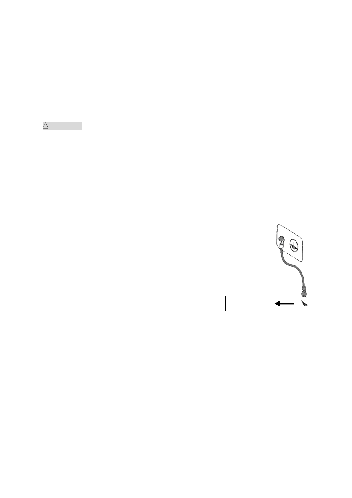
There is a protective grounding terminal on the rear panel of the tester chassis,
please use a dedicated tool to connect it to an electrical ground (safety ground,
earth). If there is no good grounding, when the circuit of the power is shorted to
the ground or any device’s power line is shorted to the ground, the tester chassis is
charged to an excessively high voltage, resulting in extreme danger, anyone who
touches such tester chassis, will result in electric shock accident, therefore, please
make sure that the protective grounding terminal is connected to the safety
ground.
3) Test Line Connection
Press【STOP】first, confirm that DANGER lamp is not lit, then connect the test line. When
connecting the test lead wire to a DUT, please connect the DUT with the test lead wire of HV2
or RTN/LOW first. It is very dangerous if the test line connection of HV2 or RTN/Low is
incomplete or dropped, because the entire DUT will be charged with high voltage.
After high voltage plug of the high voltage test lead is inserted into HV1 and HV2, it must be
rotated 90 degrees clockwise to prevent the test lead wire from falling off.
Before testing, it is a must to check whether the test lead wire of HV1 and HV2 or RTN/LOW are
connected, loose or fall off.
4) Stop (Pause) Test
To change the test conditions, please press the STOP once first, this will take the tester out of
the test preparation state and ensure that the DANGER lamp is off. If need to take a break or
leave the test location, please switch off the power, to prevent the accidental contact with the
start switch and cause a safety hazard.
5) Remote Control
Be very careful when operating the tester in remote control mode, because the start and stop of
Safe ground

◇9
high voltage is remote controlled, the operator can not know the actual working state of the tester
through the interface. Please pay special attention to the reliability of remote control
connection:
「STOP」key, must be connected reliably,「STOP」key must be pressed before changing the
DUT.
When working in a crowded work environment, the remote control switch must have a
interlock 「INTLOCK 」and the high voltage indicator. Disconnect the interlocker
「INTLOCK」before changing the DUT.
When testing voltage output, the operator or any other person is prohibited from touching the
DUT, test lines, probes, output terminals and areas around them.
6) Test Completion Confirmation
If you have to touch the high pressure area such as the DUT, test leads, probe or output
terminal because of reconnection or other test-related conditions, please confirm:
The power switch is turned off or the working status of the tester is not in the test state,
and DANGER lamp has gone out.
The DUT may be charged with high voltage even after the test completion, please pay
special attention that whether or not the DUT is fully discharged.
7) High Voltage Testing Discharge
In high voltage testing, test lead wires, probes and DUT are all charged with high voltage. The
tester is equipped with a discharge circuit, but some time it still requires to discharge after the
output is cut off. There is a danger of electric shock during discharge, do not touch anything that
could cause an electric shock. As soon as the output is cut off, the tester’s discharge circuit
starts forced discharging. Do not disconnect the DUT during a test or prior to the completion of
discharging.
Discharge time:
The time at which the voltage is completely discharged is determined by the test voltage used
and the characteristics of the DUT.
During the test process, discharge of the DUT is conducted by the transformer secondary
winding (approximately resistance of 2k) and approximately 0.1S is required for 10uF capacitor
with high voltage of 6000V to discharge to 30V. The fixed discharge time of the tester is 0.2s,
which ensures complete discharge of the tester. The internal filter capacitor of the tester is
discharged through the discharge circuit, which ensures complete discharge of the tester within
0.2S.
Assume that a high voltage is applied to a DUT, equivalently, a high voltage is applied to a
circuit with a 0.01uF capacitor in parallel with a 100MΩ resistor, if the DUT is disconnected
during a test or prior to the completion of discharging, approximately 5S is required for DUT
with high voltage of 5000V to be discharged to 30V, approximately 3.5S is required for DUT
with high voltage of 1000V.
Computational formula of discharge time: t = -In (30 / U) ×R×C
t: discharge time
30: discharge residue safty voltage 30V
U: test set voltage
R: discharge impedance of the DUT, approx. 2KΩ

◇10
C: capacitance of the DUT
If the time constant of the DUT is known, then the time required to discharge to 30V can be
calculated by the above formula after the output is cut off.
8) Turn ON or OFF the Power Switch
Once the power switch is turned off, be sure to allow several seconds or more before turning it ON
again, never turn on and off the power switch repeatedly, so as not to cause erroneous actions.
Especially in the state of high-voltage output, it is very dangerous to continuously turn on and off
the switch. When turn or off the power switch, no items should be connected to the high
voltage output terminals to avoid danger due to abnormal high voltage output.
9) Do Not Touch the High VoltageArea in Test Status
While the tester is in test state, there is hazardous high voltage electricity on the high voltage
output, high voltage test line, high voltage probe, DUT and their exposed conductor’s
surroundings, please do not approach or touch these areas.
Warning: Do not touch the alligator clip on the test line. When the instrument is in the test
state, the rubber skin on the alligator clip is not insulated enough, it is very
dangerous to touch it!
10) Do not short the output terminal to the earth ground
Do not short circuit the high voltage output cable, grounding wire and transmission line or the
grounding wire of other connectors or AC power to avoid the entire tester’s chassis being charged
to a very dangerous voltage. To short the high voltage output terminal HV1 to HV2 or RTN/LOW,
the entire housing of the tester must be reliably connected to the ground.
11) Do not connect external voltage to the test terminal
Do not apply a voltage from any external device to the output terminals of the tester. The tester
does not have an external discharge function in the non-discharge state. The tester may be
damaged if its output terminals are subject to an external voltage.
2.2Handling Meansures
1) Actions When in Emergency
In case of an emergency (such as electric shock hazard or burning of DUT) while the tester’s high
voltage output is not cut off, take the following actions. You may do either (a) or (b) first. But be sure
to do both:
a. Turn OFF the power switch of the tester.
b. Disconnect the AC power cord of the tester from the AC line receptacle.
2) Handling for Dangerous State of Faulty Tester
Under the following circumstances, all problems occurred are regarded as very dangerous, even if
【STOP】key is pressed, its output terminal may still delivering high voltage, therefore, you must be
extremely careful.
When【STOP】is pressed, DANGER indicator light is still on.
The voltmeter has no voltage reading, but DANGER indicator light is still on.
When above situations occur, please immediately turn OFF the power switch and disconnect the AC
power cable from the AC line receptacle. Immediately keep far away from the instrument and confirm
no risk of the test circuit by the technical personnel; or keep the instrument still for more than one
hour and confirm no output voltage in the test terminal. Remove the relevant connecting lines and
send the instrument back to us for maintenance.

◇11
Warning: Keep away from the instrument after turning off the power and prevent other people
from approaching. Do not immediately disassemble the test circuit. Immediately call our
distributor or agent. High voltage may remain in the interior of the instrument. It is hazardous
for an unqualified person to attempt to troubleshoot any tester problem.
3) DANGER Indicator Failure
When 【START】key is pressed, there is already a reading on the voltmeter, but the DANGER
indicator is still not lit, it may be that the indicator light is faulty, please shut down the tester
immediately and have it returned to our company to check and repair.
4) Long-Term Use without Failures
If the high limit is set to 100.0mA (at withstand voltage testing), please pay attention to the
temperature change, suspend use if the ambient temperature exceeds 40℃, wait till the temperature is
returned to the normal level, please be sure to check.
5) Replace the Fuse
To prevent electric shock, be sure to turn off the power switch and unplug the AC power cord before
checking and replacing the fuse, remove the fuse holder located in the power socket, take out the fuse
and press the new fuse into the fuse holder, then press into the power outlet.
!
WARNING: Make sure the fuse used is identical to the ones described on the manual, including
the shape, grade, characteristics etc. If different type of fuse is used or short circuit, then the tester
may be damaged.
6) AC Power source
The AC input power used by this tester is 100V~240VAC, frequency is 47Hz~63Hz. If the power
supply is very unstable, this will cause the action inaccurate or action abnormal, therefore, please use
an appropriate device to convert to a stable power source, such as a power stabilizer.
7) Output Power 500VA
When the DUT draws a large amount of current, prior to the determination of the defective products
and output current cut off, there is possible inflow of large current (approximate tens of amps) which
can last tens of milliseconds, the same situation may also apply prior to testing, therefore, must pay
attention to the capacity of the power cord and the applicable current line that is used together with
other instruments or devices.
8) Keep Test Lead Far Away from the Panel
When in test, please keep the high voltage cable or DUT at least 30cm away from the panel, avoid
high voltage interference monitor.
9) Precautions When Connecting Automation Equipment
The grounding system of the tester and the automation equipment must be connected together.
Install the anti-interference magnetic ring on the two ends (device output end and DUT end) of
high voltage cable and RTN/LOW test line, and wind the wire at least more than one turn.
High voltage cable and RTN/LOW test line must be separated from the control wire.
High voltage cable and RTN/LOW test line must be kept at an appropriate distance from the
tester/panel.

◇12
Chapter 3 Panel Description
The contents of this chapter are only for a brief description. For details of operation and detailed
explanation, refer to Chapter 4 for the corresponding content.
3.1 Front Panel
Figure 3-1 gives a brief description of the front panel.
Figure 3-1
1. POWER
Turn AC power ON or OFF.
2. START key (green and square) and STOP key (red and round)
START key: used to start the test, once the test starts, the DANGER indicator lights up.
STOP key: used to stop the test; it can also be used to cancel the prompt status such as PASS, FAIL
etc.
3. USB Interface
It is used to externally connect to USB storage.
4. Brand and Model
5. PrtScn key
Screenshot key, it is used to capture the current screen image to the USB memory and USB need to
be inserted into the front panel jack in advance.
6. F1~F6 Selection key
There are different functions under different screens. There are corresponding function options on
the right side of the screen for quick selection. If the description text is blank or gray, it means the
corresponding key is invalid.
7. FILE key
File shortcut key, the internal and external files can be checked.
8. Function Area (FUNCTION)
TEST key: press the key and the corresponding key lights up, the instrument is ready to test;
SETUP key: press the key and the corresponding key lights up, the instrument enters parameter
7
14
11
11
12
13
4
8
8
5
1
2
3
0
15
6
9
10

◇13
setting interface;
SYSTEM key: press the key and the corresponding key lights up, the system setting interface will
be displayed;
9. Arrow Key
Move the cursor on the screen, the selected parameter is displayed in blue.
10. Numeric keypad
Enter numbers or enter characters (file names) when needed.
11. Indicator Area
PASS: when the test data does not exceed the set data after the test, the tester will light in PASS;
FAIL: when the test data exceeds the set data in test, the tester will light in FAIL;
DANGER: as soon as the test starts, this key will light up, indicating that the test is in progress,
there is a high voltage being output.
12. HV1 Terminal
The high potential terminal of high voltage output, this is the high voltage output terminal, when
DANGER light is on, it means there is high voltage delivering, touching is forbidden.
13. HV2 Terminal
RTN terminal of high voltage output (only for TH9110, when GFI is set to FLOAT), when
DANGER light is on, it means there is high voltage delivering, touching is forbidden.
14. RTN/LOW Terminal
High voltage test reference terminal, which is low potential terminal.
15. LCD Screen
Display test information.
3.2 Rear Panel
Figure 3-2 gives a brief description of the rear panel.
Figure 3-2
1. HV2 Terminal
RTN terminal of high voltage output (only for TH9110, when GFI is set to FLOAT), when
DANGER light is on, it means high voltage is delivering, touching is forbidden.
2. HV1 Terminal
The high potential terminal of high voltage output, this is the high voltage output terminal, when

◇14
DANGER light is on, it means there is high voltage delivering, touching is forbidden.
3. RTN/LOW Terminal
High voltage test reference terminal, which is low potential terminal.
4. INTER LOCK
Only when the two ends are short circuited, high voltage output is allowed.
5. HANDLER Interface
This interface controls the start/stop of the instrument and outputs test results. For details, refer to
the instrument HANDLER interface description chapter.
6. RS232C Serial Interface
Serial communication interface can realize the communication with the computer.
7. LAN Interface
LAN communication interface can realize the communication with the computer.
8. USB Device interface
Through USB DEVICE communication interface, the computer can control the instrument by using
the control instruction commands.
9. GPIB (Option)
It provides a universal parallel communication interface between the instrument and external
devices. All parameter settings, commands, etc. can be set and obtained by the computer to realize
remote control without the instrument panel.
10. Protective Earth Terminal
Safety grounding terminal, to be used to connect instrument to the ground, please use a dedicated
tool to have it grounded securely.
11. Power Jack
AC power outlet and fuse holder, a three-wire power supply and fuse socket.
◇15
Chapter 4 Basic operation
4.1 Interface structure overview
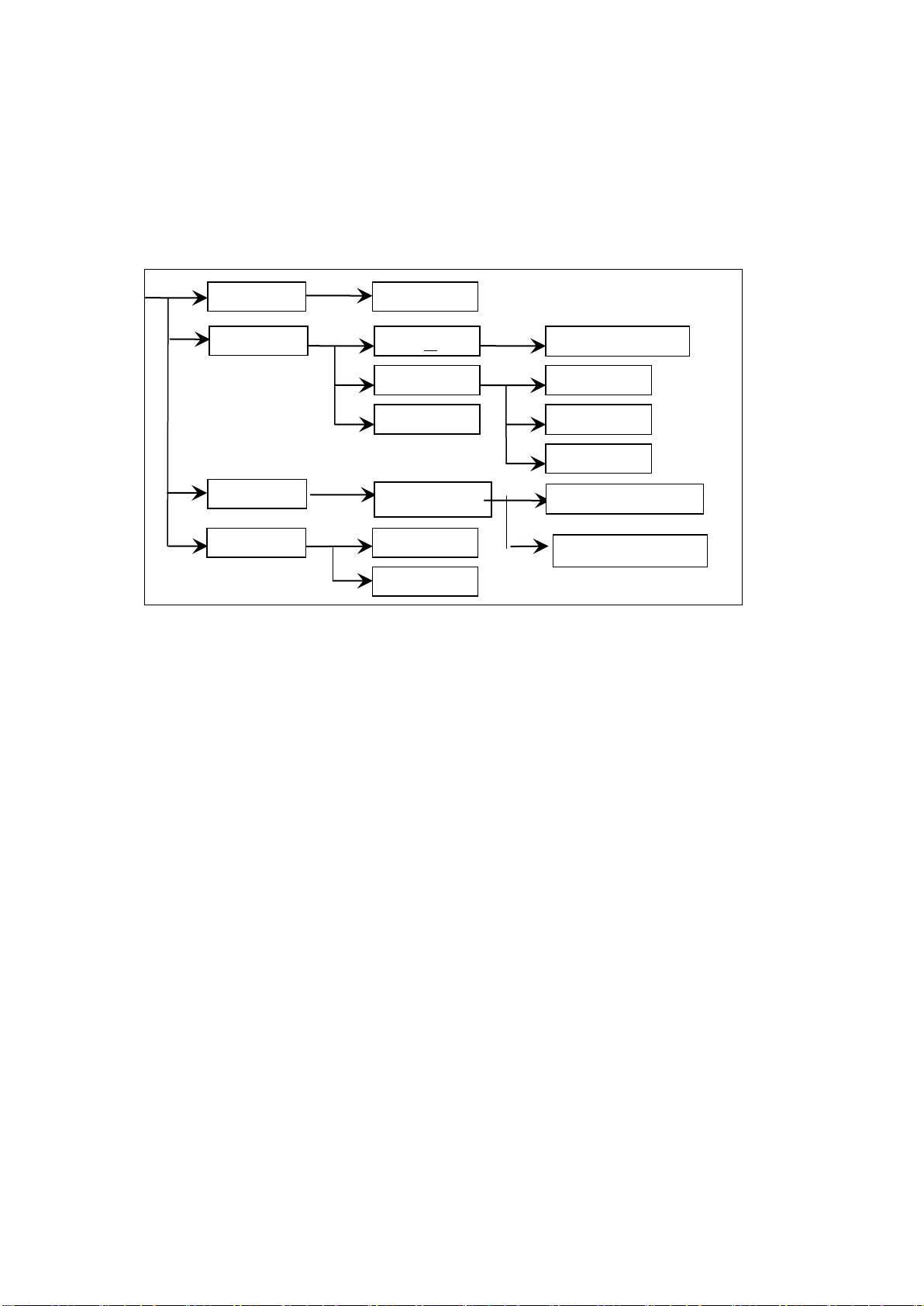
The following figure is the interface structure:
Figure 4-1 Operation Steps
Interface Instructions:
The first line in the interface structure shows the initial states corresponding to the function
keys on the panel (specific interface parameters are described in details later). The TEST
interface cannot modify parameters.
The second line in the interface shows the parameter structures of the initial interface. For
example: STEP 01/01 in the SETUP interface means that it is the step 1 of the programme and
the total steps is 1; AC: means the AC withstanding voltage test interface; AC parameter means
that other parameters are AC withstanding voltage test parameters.
The third line in the interface is the function toggle interface. When some function lablels are
selected in the second interface, the corresponding functions can be changed and their relative
parameters will also vary. For instance, changing AC to DC, the tester will change from the AC
withstanding voltage test mode to the DC withstanding voltage test mode, and the current AC
parameter will be changed into DC parameter.
SETUP
SYSTEM
SAVE
OSC
STEP:01/01
FILE
AC Parameters
Insert Delete Save
AC(AC WV)
Test Parameters
IR
DC (DC WV)
TEST
Start Test
Communication Setup
Environment Parameter
LOAD
◇16
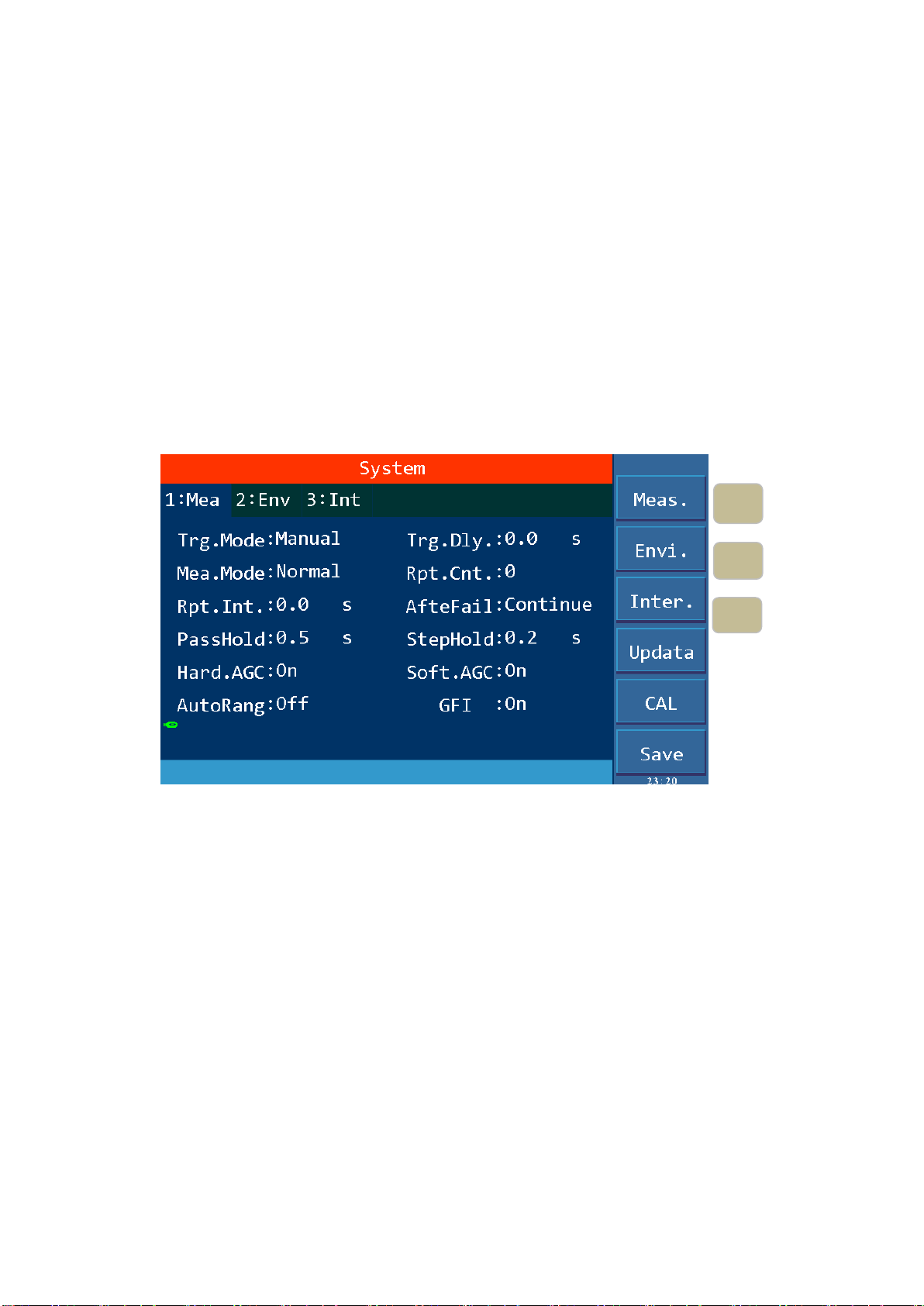
4.2 SYSTEM Setup
4.2.1 System Test Parameter Settings
Operation Instructions:
1. Press 〖SYSTEM〗key to enter the system setting interface shown in Figure 4-2.
2. Press F1~F3 key to change the measurement, environment and interface related system settings.
3. Press〖▲〗,〖▼〗key to move the cursor to the parameters you want to set. Change the
parameter settings with F1~F6 keys or numeric keys.
4. If you need to input with the numeric keys, press〖ENTER〗to confirm,〖ESC〗key to reset,
and 〖BAS〗key to delete the incorrectly entered numbers or letters.
Test related parameters setting in SYSTEM are shown in Figure 4-2:
Figure 4-2 SYSTM Test Parameter Settings
F1
系
统
设
置
中
测
试
相
关
参
数
设
置
如
图
4-2
所
示
1
系
统
设
置
中
测
试
相
关
参
数
设
置
如
F2
co
m
F3
co
m
◇17
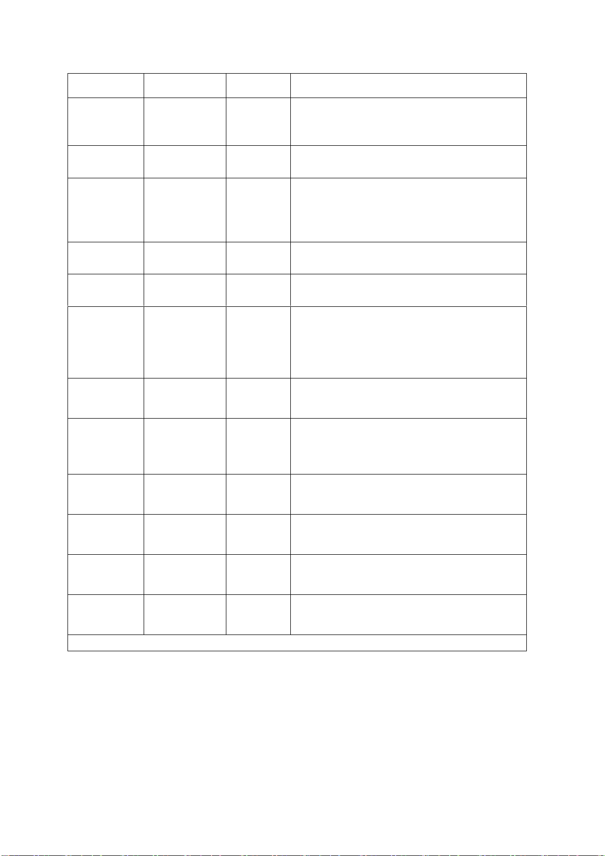
Setup items
Range
Default
Explanation
Trg. Mode
Manual
External
Bus
Manual
Set the trigger mode of the instrument to start the
test, only accept the trigger signal in the current
trigger mode.
Trg. Dly
0.0~99.9S
0.0S
Set the delay time from the receipt of the trigger
signal to the start of the measurement.
Mea. Mode
Normal
Repeat
Continue
Normal
Normal: Only one test is performed according to
the file settings.
Repeat: Perform the test multiple times as set up.
Continue: Uninterrupted continuous cycle test.
Rpt. Ctn.
0~999
0
For the above repeated test mode, repeat count
can be set.
Rpt. Int.
0.0~99.9S
0.0S
For repeated and continuous tests, set the time
interval between two tests.
AfterFail
Continue
Restart
Stop
Continue
The test fails, that is, after the instrument reports
FAIL, it can be set to continue the next test, or
press [START] to restart, or press [STOP] first,
then press [START] to start the test.
PassHold
0.2~99.9S
0.5S
Set the duration of the buzzer sound when in
PASS.
StepHold
0.2~99.9S/key
0.2S
Set the time interval between test steps, the key
means to press [START] to continue test after the
test stopped.
HardAGC
ON/OFF
ON
Set the hardware automatic gain compensation
function to ON or OFF.
SoftAGC
ON/OFF
ON
Set the software automatic gain compensation
function to ON or OFF.
AutoRange
ON/OFF
OFF
Set the withstanding voltage automatic shift
function to ON or OFF.
GFI
ON/OFF/FLOAT
ON
Set the electric shock protection function to ON
or OFF.
Table 4-1
4.2.1.1 Trigger mode
The tester can only start the test after receiving the trigger signal. This tester has four kinds of
trigger modes: manual, external (EXT), BUS, automatic. The tester can only accept the trigger
signal in the current trigger mode and the trigger signal is only valid under the TEST interface.

◇18
Before the completion of one measurement, the tester ignores other triggers. It can only be triggered
again after the measurement is finished, or press the【STOP】key to exit the current measurement,
and then trigger the measurement again.
Manual trigger: press the【START】key on the panel to start measuring.
External trigger: input a low level greater than 10mS through the external HANDLER interface
board.
Bus Trigger: Start the test by sending a trigger signal through the RS232C or GPIB interface.
The bus trigger mode can only be set by using bus commands. For details, please refer to Chapter 5.
4.2.1.2 After Fail
After Fail is test fail, which refers to the setup of handling measures after the test reports FAIL, it is
divided into continue, restart and stop test.
1. When it is set to CONTINUE, when any of the STEPs determines that the DUT is defective, the
test will continue until all the STEPs are completed.
2. When it is set to RESTART, when any of the STEPs determines that the DUT is defective, you
can directly press the【START】key to restart the test.
3. When it is set to STOP, when any of the STEPs determines that the DUT is defective, you must
press the【STOP】key before pressing the [START] key to restart the test.
4.2.1.3 Hardware/Software Compensation
Due to the output impedance of the test signal source, the load effect that is the load change, the
output voltage changes accordingly, the compensation function is used.
AC withstand voltage ACV: 50V ~ 5KV (hardware compensation is always ON, software
compensation is ON by default and it can be set to OFF)
DC withstand voltage DCV: 50V ~ 499V (hardware compensation is ON by default and it can be
set to OFF; software compensation is ON by default and it can be
set to OFF)
DCV: 500V ~ 6KV (hardware compensation is always ON, software
compensation is ON by default and it can be set to OFF)
Insulation resistance IR: 50V~499V (hardware compensation is ON by default and it can be set
to OFF; software compensation is ON by default and it can be set to
OFF)
IR: 500V ~ 5KV (hardware compensation is always ON, software
compensation is ON by default and it can be set to OFF)
As shown in Figure 4-3: Vo / Vs = RL / (Rs + RL)
Hardware compensation: Vo<Vs due to load effect, using a hardware comparison circuit, Vo
can be compensated to the same voltage as Vs in 0.1S.
Software compensation: Due to the slow speed of software compensation, it will not cause a
transient voltage shock on the DUT. Moreover, the general IR’s impedance (RL) is much larger
than the output impedance (Rs) of the tester, so Vo ≈ Vs.

◇19
Figure 4-3
4.2.1.4 Auto Range
When the auto range, that is, the withstand voltage auto range function is set to ON, at 0.6S before
the completion of the test, if the measured current can be expressed by the low current range, the
current range is automatically changed to the low current range. Examples are shown in Figure
4-4.1 and Figure 4-4.2 and Figure 4-4.3.
1. If the current range in TEST is set as high current range, 100mAin Figure 4-4.1.
Figure4-4.1
2. But the actual current is comparatively small, 0.4mAas shown in Figure 4-4.2.

◇20
Figure4-4.2
3. At 0.6S before the completion of the test, the current range is switched to the appropriate low
range, which is 0.092mAin Figure 4-4.3.
Figure4-4.3
4.2.1.5 Electric Shock Protection
Note: The output power of this tester can reach 500VA and the output current reaches 100mA (AC
withstand voltage testing mode). In the event of an electric shock, the situation is already very
serious, causing the operator to stun or even die. Therefore, in case that the tester allows, turn on the
electric shock protection function or select the high-voltage floating output tester (TH9110).
The electric shock protection setting has three options, namely OFF, ON and FLOAT (only TH9110
has high-voltage floating output function). OFF and ON means the function is turned off and on.
FLOAT means that the two high voltage output HV1 (high end), HV2 (low end) are isolated from
the earth (with very high insulation resistance), for details, see the floating part description below.
a) When the electric shock protection is set to ON, when the operator is in contact with the high
voltage output terminals, as shown in Figure 4-5, the current meter measures different current
values respectively, then the current flowing through the body i3 = i2 –i1, when i3 exceeds the
limit, immediately cut off the high voltage output to protect the safety of the operator.
Figure 4-5
b) When the electric shock protection is set to FLOAT, the high-voltage output high terminal HV1,
This manual suits for next models
1
Table of contents
Other Tonghui Electronics Test Equipment manuals


