Monacor CT-3 User manual

ELECTRONICS FOR SPECIALISTS ELECTRONICS FOR SPECIALISTS ELECTRONICS FOR SPECIALISTS ELECTRONICS FOR SPECIALISTS ELECTRONICS FOR SPECIALISTS ELECTRONICS
CT-3 Bestellnummer 29.1340
MONACOR INTERNATIONAL GmbH & Co. KG • Zum Falsch 36 • 28307 Bremen • Germany
Copyright©by MONACOR INTERNATIONAL. All rights reserved. A-1716.99.03.02.2017
SPEAKER-4P XLR-/F-3P XLR/F-5P DIN-3P/5P/7P/8P
SPEAKER-4P XLR-/M-3P XLR/M-5P DIN-3P/5P/7P/8P
ILLUMINATED LEDs INDICATE CORRESPONDING PINS
CONNECTED.
BANANA CONNECTORS:
CONTINUITY TEST WITH BEEPER AND LED.
ILLUMINATED GROUND LED INDICATES
CONNECTION FROM PIN TO SHELL (SHORT CIRCUIT).
ROTARY SWITCH FULLY CLOCKWISE:
BRIGHT LED INDICATES CHARGED BATTERY
.
SPEAKER-8P SPEAKER-8P
2 345
1 6 7 8
TRS
TRS
RJ 45
RCA
RCA
BATT.
CHECK
TRS
1 = SLEEVE
2 = TIP
3 = RING
1 = −1
2 = +1
3 = −2
4 = +2
5 = −3
6 = +3
7 = −4
8 = +4
SPEAKER RCA
1 = SCREEN
2 = HOT
CT-3 CABLE TESTER
XLR-3P
1 = 1( )
2 = 2(+)
3 = 3( )
GND (RED)
CONTINUITY
TEST
(GREEN)
3
4
2
1
12
11
10
5
13
14
615
8 17
716
9 18
19
21
23
24
25
22
20
Kabeltestgerät
Diese Anleitung richtet sich an Anwender mit techni-
schem Grundverständnis. Bitte lesen Sie diese Bedie-
nungsanleitung vor dem Betrieb gründlich durch und
heben Sie sie für ein späteres Nachlesen auf.
1 Verwendungsmöglichkeiten
Das CT-3 dient zur Überprüfung gängiger Audio- und Da-
tenkabel und ist damit ein nützliches Werkzeug, nicht nur
im Bühnenalltag. Die Verbindung der Kontakte aller An-
schlüsse wird über LEDs angezeigt. Der Durchgangsprüfer
mit optischem und akustischem Signal bietet die optimale
Ergänzung zum Überprüfen aller anderen Verbindungen.
2 Wichtige Hinweise für den Gebrauch
Das Gerät entspricht allen relevanten Richtlinien der EU
und ist deshalb mit gekennzeichnet.
•
Setzen Sie das Gerät nur im Innenbereich ein. Schützen
Sie es vor Feuchtigkeit, Hitze und Kälte (zulässige Ein-
satztemperatur 0–40°C).
•
Verwenden Sie zum Reinigen nur ein trockenes, weiches
Tuch, auf keinen Fall Chemikalien oder Wasser.
•
Wird das Gerät zweckentfremdet, falsch angeschlossen,
nicht richtig bedient, überlastet oder nicht fachgerecht
repariert, kann keine Haftung für daraus resultierende
Sach- oder Personenschäden und keine Garantie für das
Gerät übernommen werden.
Soll das Gerät endgültig aus dem Betrieb genom-
men werden, übergeben Sie es zur umweltgerech-
ten Entsorgung einem örtlichen Recyclingbetrieb.
Verbrauchte Batterien dürfen nicht in den Hausmüll
geworfen werden. Geben Sie sie nur in den Sondermüll
(z.B. Sammelbehälter bei Ihrem Fachhändler).
3 Bedienung
3.1 Batterie einlegen/auswechseln
1) Den Batteriehalter (25) nach oben schieben, sodass er
ausrastet und dann herausziehen.
2) Wenn vorhanden, die verbrauchte Batterie herausneh-
men.
3) Eine 9-V-Blockbatterie oder einen entsprechenden Akku
in den Batteriehalter einsetzen (Polung beachten!).
4) Den Batteriehalter wieder in das Batteriefach schieben
und zum Schluss nach unten drücken, sodass er ein-
rastet.
Bei längerem Nichtgebrauch die Batterie herausnehmen.
So bleibt das Gerät bei einem eventuellen Auslaufen der
Batterie unbeschädigt.
3.2 Batterie überprüfen
Um den Ladezustand der Batterie zu prüfen, den Wahl-
schalter (21) in die Position BATT. CHECK drehen. Leuchtet
die LED (22) nicht oder nur schwach, ist die Batterie ver-
braucht und sollte erneuert werden.
3.3 Kabel überprüfen
1) Stellen Sie sicher, dass das zu prüfende Kabel span-
nungsfrei ist (also z.B. nicht mit einem Ende noch am
Verstärker angeschlossen ist).
2) Den Stecker des einen Kabelendes an eine der Buchsen
(1–9) auf der linken Seite, den Stecker des anderen Ka-
belendes an eine der Buchsen (10–18) auf der rechten
Seite anschließen.
3) Mit dem Drehschalter (21) nacheinander die Kontakte
der auf der linken Geräteseite genutzten Anschluss-
buchse anwählen. Aus der Tabelle geht hervor, welcher
Kontakt jeweils der eingestellten Positionsnummer ent-
spricht.
Besteht eine Verbindung von dem gewählten Kontakt zu
einer Buchse auf der rechten Gehäuseseite, leuchtet in der
unteren LED-Zeile (20) die entsprechende LED. Die obere
LED-Zeile (19) zeigt an, mit welchen Kontakten der Buchse
auf der rechten Seite der gewählte Kontakt verbunden ist.
Bei Verwendung der DIN-Buchse leuchtet zusätzlich die
LED GND (23) rot, wenn der gewählte Kontakt mit dem
Steckergehäuse und der Abschirmung des Kabels verbun-
den ist.
Beim Anschluss von 2-poligen Klinkensteckern werden
die Kontakte 1 und 3 durch den Stecker miteinander ver-
bunden, daher leuchten in der oberen LED-Reihe (19) beide
LEDs.
3.4 Durchgangsprüfer
An die beiden 4-mm-Bananenbuchsen (24) des Durch-
gangsprüfers die beiliegenden Prüfkabel anschließen. Die
Prüfspitzen an die beiden Enden der zu testenden, span-
nungsfreien Leitung halten. Bei bestehender Leitungsver-
bindung ertönt ein Signal und die LED zwischen den Buch-
sen leuchtet grün.
4 Transport
Beim Transport des Gerätes darauf achten, dass die An-
schlüsse nicht versehentlich durch leitende Gegenstände
verbunden werden. Sonst ist möglicherweise die Batterie
beim nächsten Einsatz verbraucht.
5 Technische Daten
Stromversorgung: . . . . . . Batterie, Typ: 9-V-Block
Einsatztemperatur: . . . . . 0–40°C
Abmessungen: . . . . . . . . 114 × 190 × 60mm
Gewicht:. . . . . . . . . . . . . 800 g
Änderungen vorbehalten.
6,3-mm-Klinke
(3, 12)
1 3 2
1+ 3 2
DIN
(6, 15) 5
1
4
7
8
6
2
3
GND
Cinch
(5, 14)
1
2
XLR
3-polig
(8)
2 1
3
XLR
3-polig
(17)
1 2
3
XLR
5-polig
(7)
1
5
4 2
3
PUSH
XLR
5-polig
(16)
1
2 4
5
3
Speaker
8-polig
(1, 10)
[4
-
][4+]
[2+]
[3
-
]
[3+]
[1
-
]
[1+]
[2
-
]
1
2
7
4
6
5
8
3
Speaker
4- oder 2-polig
(9, 18)
4[2
-
][2+]
2
1
[1
-
] [1+]
3
2
1
[1
-
]
[1+]
Modularbuchse
8P8C „RJ45“
(2, 11) 1…8
USB 1/2 Typ A
(4, 13)
1 2 3 4
Deutsch

ELECTRONICS FOR SPECIALISTS ELECTRONICS FOR SPECIALISTS ELECTRONICS FOR SPECIALISTS ELECTRONICS FOR SPECIALISTS ELECTRONICS FOR SPECIALISTS ELECTRONICS
MONACOR INTERNATIONAL GmbH & Co. KG • Zum Falsch 36 • 28307 Bremen • Germany
Copyright©by MONACOR INTERNATIONAL. All rights reserved. A-1716.99.03.02.2017
SPEAKER-4P XLR-/F-3P XLR/F-5P DIN-3P/5P/7P/8P
SPEAKER-4P XLR-/M-3P XLR/M-5P DIN-3P/5P/7P/8P
ILLUMINATED LEDs INDICATE CORRESPONDING PINS
CONNECTED.
BANANA CONNECTORS:
CONTINUITY TEST WITH BEEPER AND LED.
ILLUMINATED GROUND LED INDICATES
CONNECTION FROM PIN TO SHELL (SHORT CIRCUIT).
ROTARY SWITCH FULLY CLOCKWISE:
BRIGHT LED INDICATES CHARGED BATTERY
.
SPEAKER-8P SPEAKER-8P
2 345
1 6 7 8
TRS
TRS
RJ 45
RCA
RCA
BATT.
CHECK
TRS
1 = SLEEVE
2 = TIP
3 = RING
1 = −1
2 = +1
3 = −2
4 = +2
5 = −3
6 = +3
7 = −4
8 = +4
SPEAKER RCA
1 = SCREEN
2 = HOT
CT-3 CABLE TESTER
XLR-3P
1 = 1( )
2 = 2(+)
3 = 3( )
GND (RED)
CONTINUITY
TEST
(GREEN)
3
4
2
1
12
11
10
5
13
14
615
8 17
716
9 18
19
21
23
24
25
22
20
Cable Tester
These instructions are intended for users with basic
technical knowledge. Please read these operating
instructions carefully prior to operating the unit and
keep them for later reference.
1 Applications
The CT-3 is designed for testing standard audio cables and
data cables and therefore is a useful tool not only for every-
day stage applications. LEDs indicate all contact connec-
tions. The continuity tester with visual and acoustic signals
is a perfect tool for testing all the other connections.
2 Important Notes
The unit corresponds to all relevant directives of the EU and
is therefore marked with .
•
The unit is suitable for indoor use only. Protect it against
humidity, high or low temperatures (admissible ambient
temperature range 0–40°C).
•
For cleaning only use a dry, soft cloth, never use chem-
icals or water.
•
No guarantee claims for the unit and no liability for any
resulting personal damage or material damage will be
accepted if the unit is used for other purposes than orig-
inally intended, if it is not correctly connected or operat-
ed, if it is overloaded or not repaired in an expert way.
If the unit is to be put out of operation definiti-
vely, take it to a local recycling plant for a disposal
which is not harmful to the environment.
Used batteries must not be placed in the household
waste. Always take them to a special waste disposal (e.g.
collection container at your retailer) for a disposal that is
not harmful to the environment.
3 Operation
3.1 Inserting/Replacing the battery
1) Push the battery support (25) upwards until it unlocks
and then remove the battery support.
2) If applicable, remove the discharged battery.
3) Insert a 9V battery or a corresponding rechargeable
battery into the battery support (observe the polarity!).
4) Push back the battery holder into the battery compart-
ment, and then push down the battery holder so that
it locks.
If the unit is not used for a longer period of time, remove
the battery. Thus, the unit will not be damaged if the bat-
tery should leak.
3.2 Checking the battery
To check the charging state of the battery, set the selector
switch (21) to the position BATT. CHECK. If the LED (22)
does not light up or only lights up dimly, the battery is
discharged and should be replaced.
3.3 Testing the cable
1) Make sure that the cable to be tested does not carry any
voltage (make sure that no cable end is connected to the
amplifier, for example).
2) Connect the plug of one cable end to one of the jacks
(1 to 9) on the left side, connect the plug of the other
cable end to one of the jacks (10 to 18) on the right side.
3) With the rotary switch (21), successively select the con-
tacts of the connection jack used on the left side of the
unit. The table indicates the contacts that correspond to
the position numbers adjusted.
If there is a connection from the selected contact to a jack
on the right side of the housing, the corresponding LED
in the lower LED row (20) lights up. The upper LED row
(19) indicates the connection of the selected contact to
the respective contacts of the jack on the right side. When
using the DIN jack, the LED GND (23) lights up in red ad-
ditionally if the selected contact is connected to the plug
housing and the screening of the cable.
When connecting 2-pole 6.3mm plugs, the contacts 1
and 3 are connected with each other by the plug, therefore
both LEDs light up in the upper LED row (19).
3.4 Continuity tester
Connect the two test cables provided to the two 4mm ba-
nana jacks (24) of the continuity tester. Hold the test probes
to the two ends of the cable to be tested, not carrying any
voltage. When there is a cable connection, the signal will
sound and the LED between the jacks will light up in green.
4 Transport
When transporting the unit, make sure that the connec-
tions are not accidentally connected by conducting objects.
Otherwise the battery will possibly be discharged the next
time it is used.
5 Specifications
Power supply: . . . . . . . . . 9V battery
Ambient temperature: . . 0 – 40 °C
Dimensions: . . . . . . . . . . 114 × 190 × 60mm
Weight: . . . . . . . . . . . . . 800g
Subject to technical modification.
6.3 mm plugs
(3, 12)
1 3 2
1+ 3 2
DIN
(6, 15) 5
1
4
7
8
6
2
3
GND
RCA
(5, 14)
1
2
XLR
3 poles
(8)
2 1
3
XLR
3 poles
(17)
1 2
3
XLR
5 poles
(7)
1
5
4 2
3
PUSH
XLR
5 poles
(16)
1
2 4
5
3
Speaker
8 poles
(1, 10)
[4
-
][4+]
[2+]
[3
-
]
[3+]
[1
-
]
[1+]
[2
-
]
1
2
7
4
6
5
8
3
Speaker
4 or 2 poles
(9, 18)
4[2
-
][2+]
2
1
[1
-
] [1+]
3
2
1
[1
-
]
[1+]
Modular jack
8P8C “RJ45”
(2, 11) 1…8
USB 1/2, type A
(4, 13)
1 2 3 4
CT-3 Order Number 29.1340
English

ELECTRONICS FOR SPECIALISTS ELECTRONICS FOR SPECIALISTS ELECTRONICS FOR SPECIALISTS ELECTRONICS FOR SPECIALISTS ELECTRONICS FOR SPECIALISTS ELECTRONICS
MONACOR INTERNATIONAL GmbH & Co. KG • Zum Falsch 36 • 28307 Bremen • Germany
Copyright©by MONACOR INTERNATIONAL. All rights reserved. A-1716.99.03.02.2017
SPEAKER-4P XLR-/F-3P XLR/F-5P DIN-3P/5P/7P/8P
SPEAKER-4P XLR-/M-3P XLR/M-5P DIN-3P/5P/7P/8P
ILLUMINATED LEDs INDICATE CORRESPONDING PINS
CONNECTED.
BANANA CONNECTORS:
CONTINUITY TEST WITH BEEPER AND LED.
ILLUMINATED GROUND LED INDICATES
CONNECTION FROM PIN TO SHELL (SHORT CIRCUIT).
ROTARY SWITCH FULLY CLOCKWISE:
BRIGHT LED INDICATES CHARGED BATTERY
.
SPEAKER-8P SPEAKER-8P
2 345
1 6 7 8
TRS
TRS
RJ 45
RCA
RCA
BATT.
CHECK
TRS
1 = SLEEVE
2 = TIP
3 = RING
1 = −1
2 = +1
3 = −2
4 = +2
5 = −3
6 = +3
7 = −4
8 = +4
SPEAKER RCA
1 = SCREEN
2 = HOT
CT-3 CABLE TESTER
XLR-3P
1 = 1( )
2 = 2(+)
3 = 3( )
GND (RED)
CONTINUITY
TEST
(GREEN)
3
4
2
1
12
11
10
5
13
14
615
8 17
716
9 18
19
21
23
24
25
22
20
Testeur de câbles
Cette notice s‘adresse aux utilisateurs avec des
connaissances techniques de base. Veuillez lire la pré-
sente notice avec attention avant le fonctionnement
et conservez-la pour pouvoir vous y reporter ultérieu-
rement.
1 Possibilités d’utilisation
Le CT-3 permet de vérifier des cordons audio et de don-
nées, c‘est donc un outil utile, pas seulement pour des ap-
plications quotidiennes sur scène. La connexion de tous les
contacts est indiquée par des LEDs. Le testeur de continuité
avec signal optique et acoustique propose un complément
optimal pour vérifier toutes les autres connexions.
2 Conseils importants
L’appareil répond à toutes les directives nécessaires de
l’Union européenne et porte donc le symbole .
•
L’appareil n’est conçu que pour une utilisation en inté-
rieur.Protégez-le de l’humidité, du froid et de la chaleur
(plage de température de fonctionnement autorisée :
0–40°C).
•
Pour le nettoyage, utilisez uniquement un chiffon sec
et doux, en aucun cas de produits chimiques ou d’eau.
•
Nous déclinons toute responsabilité en cas de dommages
matériels ou corporels résultants si l’appareil est utilisé
dans un but autre que celui pour lequel il a été conçu,
s’il n’est pas correctement branché ou utilisé, s’il y a sur-
charge ou s’il n’est pas réparé par une personne habili-
tée, en outre, la garantie deviendrait caduque.
Lorsque l’appareil est définitivement retiré du
service, vous devez le déposer dans une usine de
recyclage adaptée pour contribuer à son élimina-
tion non polluante.
Ne jetez pas les batteries usagées dans la poubelle do-
mestique. Déposez- les dans un container spécifique (par
exemple chez votre revendeur) pour leur recyclage non
polluant.
CARTONS ET EMBALLAGE
PAPIER À TRIER
3 Utilisation
3.1 Insertion et changement de la batterie
1) Poussez le support de batterie (25) vers le haut pour
qu‘il se désenclenche et puisse être retiré.
2) Retirez la batterie déchargée, si existante.
3) Insérez une batterie 9V ou un accumulateur correspon-
dant (attention à la polarité !).
4) Replacez le support de batterie dans le compartiment,
puis appuyez vers le bas pour qu‘il s‘enclenche.
En cas de non utilisation prolongée, retirez la batterie, elle
pourrait couler et endommager l’appareil.
3.2 Vérification de la batterie
Pour vérifier l’état de charge de la batterie, tournez le sé-
lecteur (21) sur la position BATT. CHECK. Si la LED (22) ne
brille pas ou brille trop faiblement, la batterie est morte et
devrait être remplacée.
3.3 Vérification de câble
1) Assurez-vous que le câble à tester n’est pas conducteur
de tension (par exemple assurez-vous qu’une extrémité
n’est pas encore reliée à l’amplificateur).
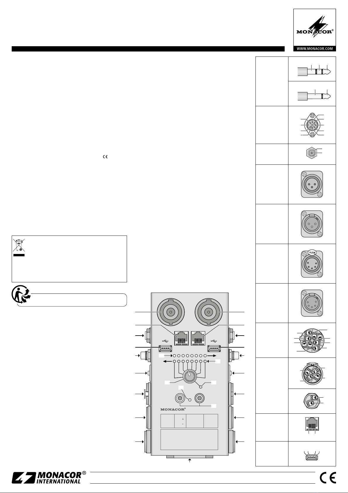
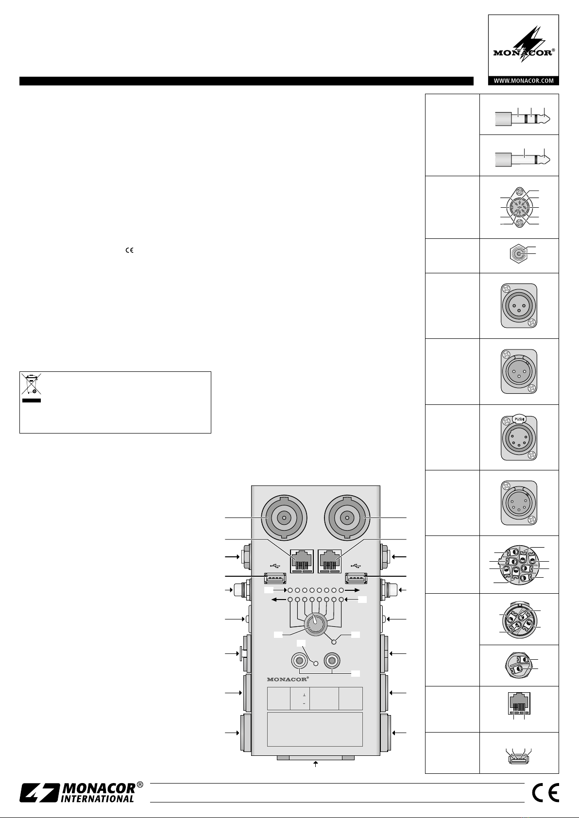
2) Reliez la fiche d’une extrémité du cordon à une des
prises (1 à 9) sur le côté gauche et la fiche de l’autre
extrémité du cordon à une des prises (10 à 18) sur le
côté droit.
3) Avec le sélecteur (21), sélectionnez les uns après les
autres les contacts de la prise de branchement utilisée
sur le côté gauche de l’appareil. Le tableau indique quel
contact correspond au numéro réglé de position dans
chaque cas.
S’il y a une connexion venant du contact sélectionné vers
une prise sur le côté droit de l’appareil, la LED correspon-
dante dans la ligne inférieure de LEDs (20) brille. La ligne
supérieure de LEDs (19) indique avec quels contacts de la
prise sur le côté droit, le contact sélectionné est relié. Si
vous utilisez la prise DIN, la LED GND (23) brille en rouge
en plus si le contact sélectionné est relié avec le corps de la
fiche et au blindage du câble.
Si vous branchez des fiches jack 6,35 2 pôles, les contacts
1 et 3 sont reliés ensemble par la fiche, par conséquent les
deux LEDs dans la ligne supérieure (19) brillent.
3.4 Testeur de passage
Reliez les cordons test livrés aux deux prises banane 4 mm
(24) du testeur de continuité. Maintenez les pointes de
touche aux deux extrémités du cordon à tester ne portant
pas de tension. Lorsque la connexion est établie, un signal
retentit, la LED entre les prises brille en vert.
4 Transport
Lors du transport de l’appareil, assurez-vous que les
connexions ne soient pas reliées par inadvertance par des
objets conducteurs. Sinon, la batterie pourrait être morte
lors de la prochaine utilisation.
5 Caractéristiques techniques
Alimentation :. . . . . . . . . batterie, type 9 V
Température fonc. :. . . . . 0–40°C
Dimensions :. . . . . . . . . . 114 × 190 × 60mm
Poids :. . . . . . . . . . . . . . . 800g
Tout droit de modification réservé.
Jacks 6,35
(3, 12)
1 3 2
1+ 3 2
DIN
(6, 15) 5
1
4
7
8
6
2
3
GND
RCA
(5, 14)
1
2
XLR
3 pôles
(8)
2 1
3
XLR
3 pôles
(17)
1 2
3
XLR
5 pôles
(7)
1
5
4 2
3
PUSH
XLR
5 pôles
(16)
1
2 4
5
3
Speaker
8 pôles
(1, 10)
[4
-
][4+]
[2+]
[3
-
]
[3+]
[1
-
]
[1+]
[2
-
]
1
2
7
4
6
5
8
3
Speaker
4 ou 2 pôles
(9, 18)
4[2
-
][2+]
2
1
[1
-
] [1+]
3
2
1
[1
-
]
[1+]
Prise modulaire
8P8C « RJ45 »
(2, 11) 1…8
USB 1/2 type A
(4, 13)
1 2 3 4
CT-3 Référence numérique 29.1340
Français

ELECTRONICS FOR SPECIALISTS ELECTRONICS FOR SPECIALISTS ELECTRONICS FOR SPECIALISTS ELECTRONICS FOR SPECIALISTS ELECTRONICS FOR SPECIALISTS ELECTRONICS
MONACOR INTERNATIONAL GmbH & Co. KG • Zum Falsch 36 • 28307 Bremen • Germany
Copyright©by MONACOR INTERNATIONAL. All rights reserved. A-1716.99.03.02.2017
SPEAKER-4P XLR-/F-3P XLR/F-5P DIN-3P/5P/7P/8P
SPEAKER-4P XLR-/M-3P XLR/M-5P DIN-3P/5P/7P/8P
ILLUMINATED LEDs INDICATE CORRESPONDING PINS
CONNECTED.
BANANA CONNECTORS:
CONTINUITY TEST WITH BEEPER AND LED.
ILLUMINATED GROUND LED INDICATES
CONNECTION FROM PIN TO SHELL (SHORT CIRCUIT).
ROTARY SWITCH FULLY CLOCKWISE:
BRIGHT LED INDICATES CHARGED BATTERY
.
SPEAKER-8P SPEAKER-8P
2 345
1 6 7 8
TRS
TRS
RJ 45
RCA
RCA
BATT.
CHECK
TRS
1 = SLEEVE
2 = TIP
3 = RING
1 = −1
2 = +1
3 = −2
4 = +2
5 = −3
6 = +3
7 = −4
8 = +4
SPEAKER RCA
1 = SCREEN
2 = HOT
CT-3 CABLE TESTER
XLR-3P
1 = 1( )
2 = 2(+)
3 = 3( )
GND (RED)
CONTINUITY
TEST
(GREEN)
3
4
2
1
12
11
10
5
13
14
615
8 17
716
9 18
19
21
23
24
25
22
20
Tester per cavi
Queste istruzioni sono rivolte a utenti con conoscenze
tecniche di base. Vi preghiamo di leggere attentamen-
te le presenti istruzioni prima della messa in funzione
e di conservarle per un uso futuro.
1 Possibilità d’impiego
Il CT-3 serve per controllare i normali cavi audio e per dati, e
pertanto è un tool utile, non solo per spettacoli. La connes-
sione dei contatti di tutti i collegamenti è segnalata tramite
LED. Il tester di continuità con segnale visivo e acustico
offre un’integrazione ottimale per verificare tutti gli altri
collegamenti.
2 Avvertenze importanti per l’uso
Quest’apparecchio è conforme a tutte le direttive rilevanti
dell’UE e pertanto porta la sigla .
•
Usare lo strumento solo all’interno di locali. Proteggerlo
dall’umidità, dal calore e dal freddo (temperatura d’im-
piego ammessa fra 0 e 40°C).
•
Per la pulizia usare solo un panno morbido, asciutto; non
impiegare in nessun caso prodotti chimici o acqua.
•
Nel caso d’uso improprio, di collegamenti sbagliati, d’im-
piego scorretto, di sovraccarico o di riparazione non a
regola d’arte dello strumento, non si assume nessuna
responsabilità per eventuali danni consequenziali a per-
sone o a cose e non si assume nessuna garanzia per lo
strumento.
Se si desidera eliminare lo strumento definitiva-
mente, consegnarlo per lo smaltimento ad un’isti-
tuzione locale per il riciclaggio.
Non gettare le batterie scariche o difettose nelle immon-
dizie di casa bensì negli appositi contenitori (p.es. presso
il vostro rivenditore).
3 Funzionamento
3.1 Inserire/sostituire la batteria
1) Spostare verso l‘alto il portabatteria (25) per farlo sbloc-
care; quindi estrarlo.
2) Se presente, togliere la batteria scarica.
3) Inserire nel portabatteria una batteria transistor a 9V
oppure una batteria ricaricabile corrispondente (rispet-
tare la polarità!).
4) Rispingere il portabatteria nel suo vano e alla fine eserci-
tare una pressione verso il basso fino allo scatto.
Se lo strumento non viene utilizzato per un tempo prolun-
gato conviene togliere la batteria per evitare che perda,
danneggiando lo strumento.
3.2 Controllare la batteria
Per controllare lo stato di carico della batteria girare il se-
lettore (21) in posizione BATT. CHECK. Se il LED (22) non si
accende o se si accende solo debolmente, significa che la
batteria è scarica e che dovrebbe essere sostituita.
3.3 Controllare i cavi
1) Assicurarsi che il cavo da controllare sia senza tensione
(cioè non collegato con l’amplificatore per mezzo di un
suo terminale).
2) Inserire il connettore di un terminale del cavo in una
delle prese (1–9) sul lato sinistro, e il connettore dell’al-
tro terminale in una delle prese (10 – 18) sul lato destro.
3) Con il selettore (21) selezionare, uno dopo l’altro, i con-
tatti del lato sinistro dello strumento. Dalla tabella si può
vedere, quale contatto corrisponde al numero imposta-
to per la posizione.
Se esiste un collegamento fra il contatto selezionato e una
presa sul lato destro del contenitore, nella riga inferiore
dei LED (20) si accende il relativo LED. La riga superiore
dei LED (19) indica con quali contatti della presa sul lato
destro è collegato il contatto selezionato. Usando la presa
DIN, si accende in più il LED GND (23) di color rosso, se il
contatto scelto è collegato con il corpo del connettore e
con la schermatura del cavo.
Collegando i jack a 2 poli, i contatti 1 e 3 vengono col-
legati tramite il connettore; perciò nella riga superiore dei
LED (19) si accendono entrambi i LED.
3.4 Tester di continuità
Collegare i cavi da testare in dotazione con le due prese
a banana di 4mm (24) del tester di continuità. Tenere i
puntali ai due terminali del cavo da testare che deve essere
privo di tensione. Se esiste un collegamento dei conduttori,
viene emesso un segnale acustico e il LED fra le prese si
accende di color verde.
4 Trasporto
Durante il trasporto dello strumento evitare che i contatti
vengano collegati involontariamente da oggetti condutto-
ri. Altrimenti, la batteria può essere scarica in occasione
dell’impiego successivo.
5 Dati tecnici
Alimentazione: . . . . . . . . batteria,
tipo: transistor 9V
Temperatura d’esercizio: . 0 – 40 °C
Dimensioni:. . . . . . . . . . . 114 × 190 × 60mm
Peso:. . . . . . . . . . . . . . . . 800g
Con riserva di modifiche tecniche.
Jack 6,3 mm
(3, 12)
1 3 2
1+ 3 2
DIN
(6, 15) 5
1
4
7
8
6
2
3
GND
RCA
(5, 14)
1
2
XLR
3 poli
(8)
2 1
3
XLR
3 poli
(17)
1 2
3
XLR
5 poli
(7)
1
5
4 2
3
PUSH
XLR
5 poli
(16)
1
2 4
5
3
Speaker
8 poli
(1, 10)
[4
-
][4+]
[2+]
[3
-
]
[3+]
[1
-
]
[1+]
[2
-
]
1
2
7
4
6
5
8
3
Speaker
4 o 2 poli
(9, 18)
4[2
-
][2+]
2
1
[1
-
] [1+]
3
2
1
[1
-
]
[1+]
Presa modulare
8P8C “RJ45”
(2, 11) 1…8
USB 1/2 tipo A
(4, 13)
1 2 3 4
CT-3 Codice 29.1340
Italiano
This manual suits for next models
1
Table of contents
Languages:
Other Monacor Test Equipment manuals

Monacor
Monacor HYB-700TEST User manual

Monacor
Monacor img Stage Line STROBE-192 User manual

Monacor
Monacor HYB-800 TEST Reference guide

Monacor
Monacor CT-3 User manual

Monacor
Monacor CT-1 User manual

Monacor
Monacor img Stage Line SL-100 User manual

Monacor
Monacor CTG-1NOISE User manual

Monacor
Monacor IMG STAGELINE STROBE-170DMX User manual

Monacor
Monacor IMG Stageline STROBE-185 User manual

Monacor
Monacor measurement OD-1200 User manual