Toolshop TS11OL227 User manual

OPERATOR’S MANUAL
TS11OL227
11 GALLON PORTABLE AIR COMPRESSOR
TS11OL227 OM Ver. 06/13
H1512FWK/-6ER04/7
CUSTOMER SERVICE
1-866-242-4298
Thank you for buying a Tool Shop product.
Your air compressor has been engineered and manufactured to Tool Shop’s high standard for dependability, ease of
operation, and operator safety. When properly cared for, it will give you years of rugged, trouble-free performance.
2
This unit was fully tested and inspected prior to shipment and will operate properly when instructions are followed. Refer to your owner’s manual for basic
troubleshooting. To avoid unnecessary return to the store, simply call Compressor Support toll free for additional assistance.
DO NOT RETURN TO STORE
IMPORTANT
STOP STOP
Compressor Support: 1-866-242-4298
(
•
Air Compressor will automatically shut off when maximum PSI is reached. When the tank pressure drops to the cut
in pressure (low pressure) and the on/off switch
is in the ON position, the unit will automatically restart.
• On occasion, maximum pressure in tank will remain until next use thus resulting in a sense of no power (See bullet above).
• To avoid power loss, overheating and ensure power, use additional air hose rather than extension cords.
• It is the consumer’s responsibility to drain oil lubed units prior to shipment to meet ICC, state and local fire regulations.
Please have your model number and serial number available. These can be found on the data label on your product. Retain a copy of your receipt with purchase
date for reference.
NOTICE
8%&0)3*'328)287-2863(9'8-32(%2+)6!!&"!%"!$ #/.35-%2
This tool has many features for making its use more pleasant and enjoyable. Safety, performance, and dependability
have been given top priority in the design of this product making it easy to mantain and operate.
PRODUCT FOR CONSUMER USE ONLY. Not intended for commercial use.
Introduction ......................................................................................................................................................................2
General Safety Rules....................................................................................................................................................3-4
Specific Safety Rules .......................................................................................................................................................5
Symbols.........................................................................................................................................................................6-7
Electrical...........................................................................................................................................................................8
Glossary of Terms ............................................................................................................................................................9
Tools Needed ...................................................................................................................................................................9
Features....................................................................................................................................................................10-11
Assembly...................................................................................................................................................................11-13
Operation...................................................................................................................................................................14-16
Maintenance...................................................................................................................................................................16
Troubleshooting..............................................................................................................................................................17
Replacement Parts List.............................................................................................................................................18-21
Warranty.........................................................................................................................................................................22
TABLE OF CONTENTS
INTRODUCTION
If this compressor is altered in any way, existing warranties shall be voided. Tool Shop disclaims any liabilities
whatsoever for any loss, personal injury, or damage.

3
WARNING:
Read and understand all instructions. Failure to
follow all instructions listed below may result in electric
shock, fire, and/or serious personal injury.
SAVE THESE INSTRUCTIONS
WORK AREA
Keep your work area clean and well lit. Cluttered
benches and dark areas invite accidents. Floor must
not be slippery from wax or dust.
Do not operate power tools in explosive atmo-
spheres, such as in the presence of flammable
liquids, gases, or dust. Power tools create sparks
which may ignite the dust or fumes.
Keep bystanders, children, and visitors away while
operating tools. Distractions can cause you to lose
control.
Operate air compressor in an open area at least 18
in. away from any wall or object that could restrict
the flow of fresh air to ventilation openings.
ELECTRICAL SAFETY
Avoid body contact with grounded surfaces such as
pipes, radiators, ranges, and refrigerators. There is an
increased risk of electric shock if your body is grounded.
Don’t expose power tools to rain or wet conditions.
Water entering a power tool will increase the risk of
electric shock.
Do not abuse the cord. Never use the cord to carry
the tool or pull the plug from an outlet. Keep cord
away from heat, oil, sharp edges, or moving parts.
Replace damaged cords immediately. Damaged
cords increase the risk of electric shock.
When operating a power tool outside, use an
outdoor extension cord marked “W-A” or “W”.
These cords are rated for outdoor use and reduce the
risk of electric shock.
PERSONAL SAFETY
Eye protection which conforms to ANSI
specifications and provides protection against
flying particles both from the FRONT and SIDE
should ALWAYS be worn by the operator and
others in the work area when loading, operating, or
servicing this tool. Eye protection is required to guard
against flying fasteners and debris, which could cause
severe eye injury.
The employer and/or user must ensure that proper
eye protection is worn. We recommend a Wide Vision
Safety Mask for use over eyeglasses or standard safety
glasses that provide protection against flying particles
both from the front and side. Always use eye protection
which is marked to comply with ANSI Z87.1.
Additional safety protection will be required in
some environments. For example, the working area
may include exposure to a noise level which can lead to
hearing damage. The employer and user must ensure
that any necessary hearing protection is provided
and used by the operator and others in the work
area. Some environments will require the use of head
protection equipment. When required, the employer
and user must ensure that head protection marked to
comply with ANSI Z89.1 is used.
Stay alert, watch what you are doing, and use
common sense when operating a power tool. Do
not use tool while tired or under the influence
of drugs, alcohol, or medication. A moment of
inattention while operating power tools may result in
serious personal injury.
Dress properly. Do not wear loose clothing or
jewelry. Contain long hair. Keep your hair, clothing,
and gloves away from moving parts. Loose clothes,
jewelry, or long hair can be caught in moving parts.
Do not overreach. Keep proper footing and balance
at all times. Proper footing and balance enables better
control of the tool in unexpected situations.
Use safety equipment. Always wear eye protection.
Dust mask, nonskid safety shoes, hard hat, or hearing
protection must be used for appropriate conditions.
Do not use on a ladder or unstable support. Stable
footing on a solid surface enables better control of the
tool in unexpected situations.
TOOL USE AND CARE
Do not exceed the pressure rating of any
component in the system.
Protect material lines and air lines from damage or
puncture. Keep hose and power cord away from sharp
objects, chemical spills, oil, solvents, and wet floors.
Check hoses for weak or worn condition before
each use, making certain all connections are
secure. Do not use if defect is found. Purchase a
new hose or notify an authorized service center for
examination or repair.
Release all pressures within the system slowly.
Dust and debris may be harmful.
Store idle tools out of the reach of children and
other untrained persons. Tools are dangerous in the
hands of untrained users.
Maintain tools with care. Follow maintenance
instructions. Properly maintained tools are easier to
control.
Check for misalignment or binding of moving parts,
breakage of parts, and any other condition that
may affect the tool’s operation. If damaged, have
the tool serviced before using. Many accidents are
caused by poorly maintained tools.
GENERAL SAFETY RULES

4
Never point any tool toward yourself or others.
Keep the exterior of the air compressor dry, clean,
and free from oil and grease. Always use a clean
cloth when cleaning. Never use brake fluids, gasoline,
petroleum-based products, or any strong solvents to
clean the unit. Following this rule will reduce the risk of
deterioration of the enclosure plastic.
SERVICE
Tool service must be performed only by qualified
repair personnel. Service or maintenance performed
by unqualified personnel may result in a risk of injury.
GENERAL SAFETY RULES
Disconnect power supply, open drain valve to
decompress tank and allow water to drain, and
allow air compressor to become cool to the touch
before servicing. Turn pressure regulator knob fully
counter clockwise after shutting off compressor.
When servicing a tool, use only identical
replacement parts. Follow instructions in the
Maintenance section of this manual. Use of
unauthorized parts or failure to follow Maintenance
instructions may create a risk of injury.

5
Know your power tool. Read operator’s manual
carefully. Learn its applications and limitations, as well
as the specific potential hazards related to this tool.
Following this rule will reduce the risk of electric shock,
fire, or serious injury.
Drain tank of moisture after each day’s use.
If unit will not be used for a while, it is best to leave drain
valve open until such time as it is to be used. This will
allow moisture to completely drain out and help prevent
corrosion on the inside of tank.
Risk of Fire or Explosion. Do not spray flammable
liquid in a confined area. Spray area must be well
ventilated. Do not smoke while spraying or spray where
spark or flame is present. Keep compressors as far from
the spraying area as possible, at least 15 feet from the
spraying area and all explosive vapors.
Risk of Bursting. Do not adjust regulator to result
in output pressure greater than marked maximum
pressure of attachment. Do not use at pressure greater
than the rated maximum pressure of this compressor.
If connected to a circuit protected by fuses, use
time-delay fuses with this product.
To reduce the risk of electric shock, do not expose to
rain. Store indoors.
Inspect tank yearly for rust, pin holes, or other
imperfections that could cause it to become unsafe.
Never weld or drill holes in the air tank.
Make sure the hose is free of obstructions or snags.
Entangled or snarled hoses can cause loss of balance
or footing and may become damaged.
Use the air compressor only for its intended use. Do
not alter or modify the unit from the original design
or function.
Always be aware that misuse and improper handling
of this tool can cause injury to yourself and others.
Never leave a tool unattended with the air hose
attached.
Do not operate this tool if it does not contain a
legible warning label.
Do not continue to use a tool or hose that leaks air
or does not function properly.
Always disconnect the air supply and power supply
before making adjustments, servicing a tool, or when a
tool is not in use.
Do not attempt to pull or carry the air compressor
by the hose.
Your tool may require more air consumption than
this air compressor is capable of providing.
SPECIFIC SAFETY RULES
Always follow all safety rules recommended by the
manufacturer of your tool, in addition to all safety
rules for the air compressor. Following this rule will
reduce the risk of serious personal injury.
Never direct a jet of compressed air toward people
or animals. Take care not to blow dust and dirt
towards yourself or others. Following this rule will
reduce the risk of serious injury.
Protect your lungs. Wear a face or dust mask if the
operation is dusty. Following this rule will reduce the
risk of serious personal injury.
Do not use this air compressor to spray chemicals.
Your lungs can be damaged by inhaling toxic fumes. A
respirator may be necessary in dusty environments or
when spraying paint. Do not carry while painting.
Inspect tool cords and hoses periodically and, if
damaged, have repaired at your nearest Authorized
Service Center. Constantly stay aware of cord
location. Following this rule will reduce the risk of
electric shock or fire.
Never use an electrical adaptor with this grounded
plug.
Check damaged parts. Before further use of the
air compressor or air tool, a guard or other part
that is damaged should be carefully checked to
determine that it will operate properly and perform
its intended function. Check for alignment of
moving parts, binding of moving parts, breakage of
parts, mounting, and any other conditions that may
affect its operation. A guard or other part that is
damaged should be properly repaired or replaced
by an authorized service center. Following this rule
will reduce the risk of shock, fire or serious injury.
Make sure your extension cord is in good
condition. When using an extension cord, be sure
to use one heavy enough to carry the current your
product will draw. A wire gauge size (A.W.G.) of at
least 14 is recommended for an extension cord 50
feet or less in length. A cord exceeding 100 feet is
not recommended. If in doubt, use the next heavier
gauge. The smaller the gauge number, the heavier
the cord. An undersized cord will cause a drop in line
voltage resulting in loss of power and overheating.
WARNING: This product contains one or more
chemicals known to the State of California to cause
cancer and birth defects or other reproductive harm.
Wash hands after handling.
Save these instructions. Refer to them frequently
and use them to instruct others who may use this air
compressor. If you loan someone this tool, load them
these instructions also.

6
7=1&307
7SQISJXLIJSPPS[MRKW]QFSPWQE]FIYWIHSRXLMWXSSP4PIEWIWXYH]XLIQERHPIEVRXLIMVQIERMRK4VSTIVMRXIVTVIXEXMSRSJXLIWIW]QFSPW[MPPEPPS[]SYXSSTIVEXIXLIXSSPFIXXIVERHWEJIV
6IEH8LI3TIVEXSVW1ERYEP
6MWOSJ&YVWXMRK6MWOSJ*MVISV)\TPSWMSR
7=1&302%1)()7-+2%8-32)<40%2%8-32
:SPXEKI'YVVIRX*VIUYIRG]G]GPIWTIVWIGSRH8]TISJGYVVIRX(SYFPIMRWYPEXIHGSRWXVYGXMSR(SRSXI\TSWIXSVEMRSVYWIMRHEQTPSGEXMSRW8SVIHYGIXLIVMWOSJMRNYV]YWIVQYWXVIEHERHYRHIVWXERHSTIVEXSVWQERYEPFIJSVIYWMRKXLMWTVSHYGX)]I4VSXIGXMSR%P[E]W[IEVWEJIX]KSKKPIWWEJIX]KPEWWIW[MXLWMHIWLMIPHWSVEJYPPJEGIWLMIPH[LIRSTIVEXMRKXLMWTVSHYGX4VIGEYXMSRWXLEXMRZSPZI]SYVWEJIX](SRSXWTVE]JPEQQEFPIPMUYMHMREGSRJMRIHEVIE7TVE]EVIEQYWXFI[IPPZIRXMPEXIH(SRSXWQSOI[LMPIWTVE]MRKSVWTVE][LIVIWTEVOSVJPEQIMWTVIWIRX/IITGSQTVIWWSVWEWJEVJVSQXLIWTVE]MRKEVIEEWTSWWMFPIEXPIEWXJIIXJVSQXLIWTVE]MRKEVIEERHEPPI\TPSWMZIZETSVW;IX'SRHMXMSRW%PIVX'PEWW--'SRWXVYGXMSR,^,IVX^%%QTIVIW::SPXW,SX7YVJEGI8SVIHYGIXLIVMWOSJMRNYV]SVHEQEKIEZSMHGSRXEGX[MXLER]LSXWYVJEGI
6MWOXS&VIEXLMRK%MVSFXEMRIHHMVIGXP]JVSQXLIEMVGSQTVIWWSVWLSYPHRIZIVFIYWIHXSWYTTP]EMVJSVLYQERGSRWYQTXMSR%PXIVREXMRK'YVVIRX7EJIX]%PIVX(SRSXEHNYWXVIKYPEXSVXSVIWYPXMRSYXTYXTVIWWYVIKVIEXIVXLERQEVOIHQE\MQYQTVIWWYVISJEXXEGLQIRX(SRSXYWIEXTVIWWYVIKVIEXIVXLER47-
6MWOSJ)PIGXVMGEP7LSGO,E^EVHSYW:SPXEKI(MWGSRRIGXJVSQTS[IVWSYVGIFIJSVIWIVZMGMRK'SQTVIWWSVQYWXFIKVSYRHIH
Do not adjust the regulator to result in output pressure greater than
the marked maximum pressure of the attachment. Do not use at a
pressure greater than the rated maximum pressure of this compressor.
7
7=1&3077)6:-')7IVZMGMRKVIUYMVIWI\XVIQIGEVIERHORS[PIHKIERHWLSYPHFITIVJSVQIHSRP]F]EUYEPMJMIHWIVZMGIXIGLRMGMER*SVWIVZMGI[IWYKKIWX]SYVIXYVRXLITVSHYGXXSXLIRIEVIWX%98,36->)(7)6:-')')28)6JSVVITEMV;LIRWIVZMGMRKYWISRP]MHIRXMGEPVITPEGIQIRXTEVXW;%62-2+8SEZSMHWIVMSYWTIVWSREPMRNYV]HSRSXEXXIQTXXSYWIXLMWTVSHYGXYRXMP]SYVIEHXLSVSYKLP]ERHYRHIVWXERHGSQTPIXIP]XLISTIVEXSVWQERYEP7EZIXLMWSTIVEXSVWQERYEPERHVIZMI[JVIUYIRXP]JSVGSRXMRYMRKWEJISTIVEXMSRERHMRWXVYGXMRKSXLIVW[LSQE]YWIXLMWTVSHYGX8LISTIVEXMSRSJER]TS[IVXSSPGERVIWYPXMRJSVIMKRSFNIGXWFIMRKXLVS[RMRXS]SYVI]IW[LMGLGERVIWYPXMRWIZIVII]IHEQEKI&IJSVIFIKMRRMRKTS[IVXSSPSTIVEXMSREP[E]W[IEVWEJIX]KSKKPIWWEJIX]KPEWWIW[MXLWMHIWLMIPHWSVEJYPPJEGIWLMIPH[LIRRIIHIH;IVIGSQQIRH;MHI:MWMSR7EJIX]1EWOJSVYWISZIVI]IKPEWWIWSVWXERHEVHWEJIX]KPEWWIW[MXLWMHIWLMIPHW%P[E]WYWII]ITVSXIGXMSR[LMGLMWQEVOIHXSGSQTP][MXL%27->
;%62-2+7%:)8,)7)-27869'8-327
8LIJSPPS[MRKWMKREP[SVHWERHQIERMRKWEVIMRXIRHIHXSI\TPEMRXLIPIZIPWSJVMWOEWWSGMEXIH[MXLXLMWTVSHYGX7=1&307-+2%01)%2-2+
(%2+)6;%62-2+'%98-32'%98-32
-RHMGEXIWERMQQMRIRXP]LE^EVHSYWWMXYEXMSR[LMGLMJRSXEZSMHIH[MPPVIWYPXMRHIEXLSVWIVMSYWMRNYV]-RHMGEXIWETSXIRXMEPP]LE^EVHSYWWMXYEXMSR[LMGLMJRSXEZSMHIHGSYPHVIWYPXMRHIEXLSVWIVMSYWMRNYV]-RHMGEXIWETSXIRXMEPP]LE^EVHSYWWMXYEXMSR[LMGLMJRSXEZSMHIHQE]VIWYPXMRQMRSVSVQSHIVEXIMRNYV];MXLSYX7EJIX]%PIVX7]QFSP-RHMGEXIWEWMXYEXMSRXLEXQE]VIWYPXMRTVSTIVX]HEQEKI
SERVICE
Servicing requires extreme care and knowledge and
should be performed only by a qualified service technician.
For service we suggest you contact Customer Service at
1-866-242-4298.
8
Replace a damage or worn cord immediately.
Replace a damaged or worn cord immediately.
SPEED AND WIRING
The no-load speed of the electric motor varies by model and
specification. The motor speed is not constant and decreases
under a load or with lower voltage. For voltage, the wiring
in a shop is as important as the motor’s horsepower rating.
A line intended only for lights cannot properly carry a power
tool motor. Wire that is heavy enough for a short distance will
be too light for a greater distance.A line that can support one
power tool may not be able to support two or three tools.
GROUNDING INSTRUCTIONS
This product must be grounded. In the event of an electrical
short circuit, grounding reduces the risk of electric shock
by providing an escape wire for the electric current. This
air compressor is equipped with an electric cord having an
equipment-grounding conductor and a grounding plug. The
plug must be plugged into a matching outlet that is properly
installed and grounded in accordance with all local codes and
ordinances.
Do not modify the plug provided. If it will not fit the outlet,
have the proper outlet installed by a qualified electrician.
The conductor with insulation having an outer surface that
is green with or without yellow stripes is the equipment-
grounding conductor. If repair or replacement of the electric
cord or plug is necessary, do not connect the equipment-
grounding conductor to a live terminal.
Check with a qualified electrician or service personnel if the
grounding instructions are not completely understood, or if in
doubt as to whether the tool is properly grounded.
Repair or replace a damaged or worn cord immediately.
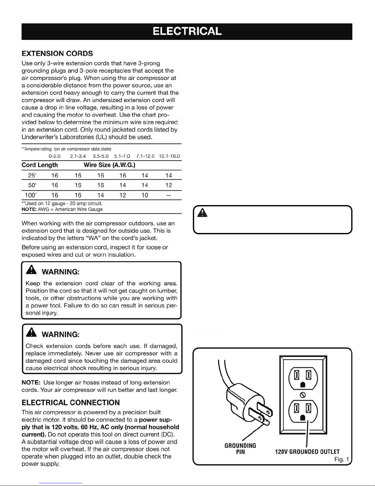
This product is for use on a nominal 120-V circuit and has
a grounding plug similar to the plug illustrated in Figure 1.
Only connect the product to an outlet having the same con-
figuration as the plug. Do not use an adapter with this product.
WARNING:
Improper connection of the equipment-grounding
conductor can result in a risk of electric shock.

9
TOOLS NEEDED
The following tools are needed in order to assemble the wheel kit.
TWO OPEN-END WRENCHES
SCFM (Standard Cubic Feet Per Minute)
A unit of measure of air delivery.
L/min (Liter Per Minute)
A unit of measure of air delivery.
Tank Pressure Gauge
Indicates the pressure in the air tank.
Thermal Overload Switch
Automatically shuts off the compressor if the temperature
of the electric motor exceeds a predetermined limit.
10
FEATURES
PRODUCT SPECIFICATIONS
Running Horsepower................................................1.2 HP
Air Tank Capacity.......................................................11 gal.
Air Pressure....................................................135 PSI max.
Air Delivery......................................... 3.2 SCFM @ 90 PSI
............................................................ 4.2 SCFM @ 40 PSI
Lubrication..............................................................Oil-Free
Gauges....... one gauge 1.5 in., one gauge 2.0 in. diameter
Input............................... 120 V, 60 Hz, AC only, 13.5 Amps
Net Weight (only compressor)................................49.6 lbs.
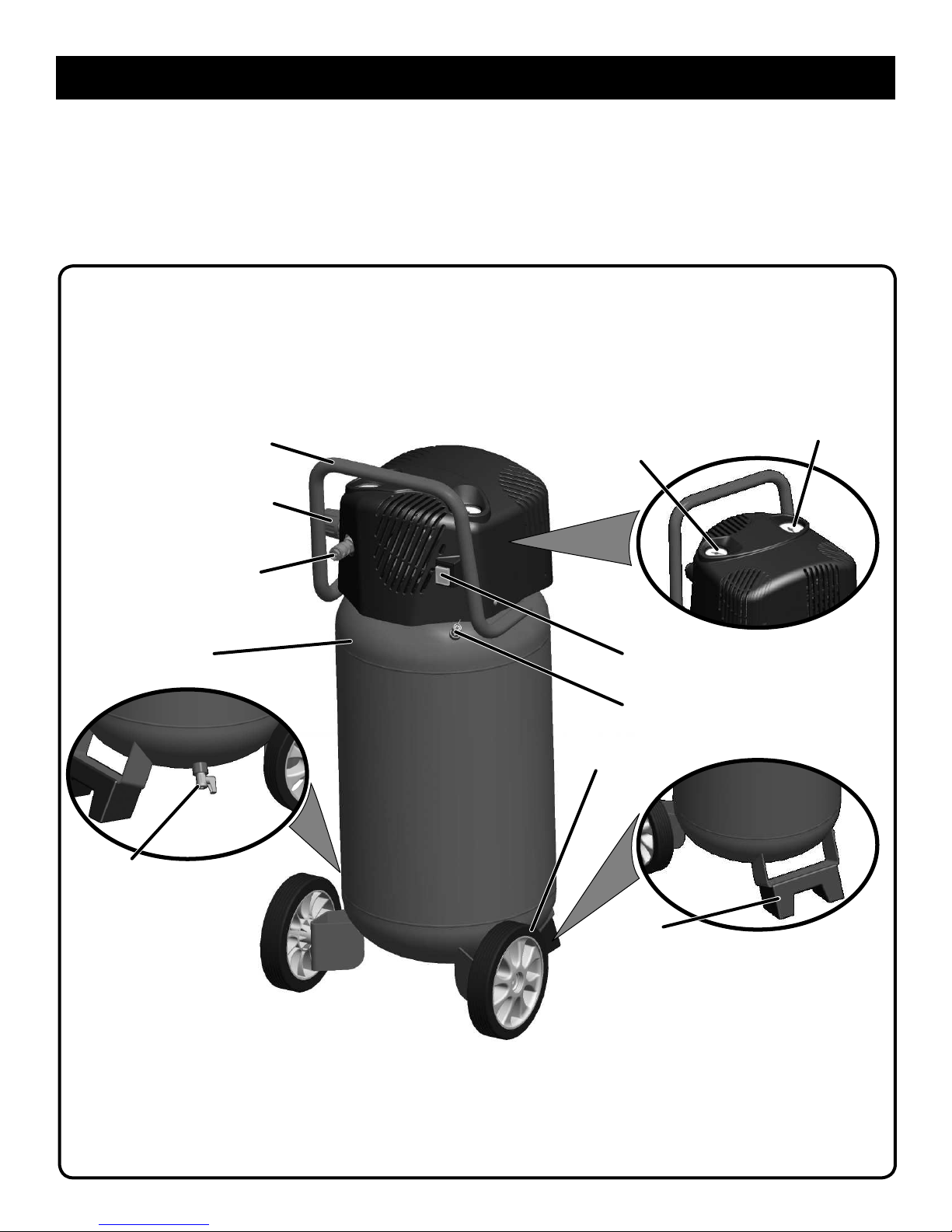
Fig. 2
PRESSURE
REGULATOR
KNOB
SAFETY
VALVE
HANDLE
TANK
WHEEL
MANUAL
ON/OFF
SWITCH
QUICK
COUPLER
RUBBER
FOOT
REGULATOR
PRESSURE
GAUGE
TANK
PRESSURE
GAUGE
DRAIN
VALVE

11
FEATURES
ASSEMBLY
UNPACKING
Carefully remove the compressor from the box. Make
sure that all items listed in the packing list are included.
I
nspect the compressor carefully to make
sure no
breakage or damage occurred during shipping.
Do not discard the packing material until you have
carefully inspected and satisfactorily operated the tool.
If any parts are damaged or missing, please call
1-866-242-4298 for assistance.
PACKING LIST
Air Compressor
Operator’s Manual
Sheet “Do not return to store”
KNOW YOUR AIR COMPRESSOR
See Figure 2.
Before attempting to use this product, familiarize yourself
with all operating features and safety rules.
OIL-FREE UNIVERSAL MOTOR
Your air compressor features permanently lubricated
bearings.
PRESSURE REGULATOR KNOB
Use the pressure regulator knob to adjust the amount of
air being delivered through the hose.
REGULATOR PRESSURE GAUGE
The current line pressure is displayed on the regulator
pressure gauge. This pressure can be adjusted by rotating
the pressure regulator knob.
SAFETY VALVE
The safety valve is designed to automatically release air if
the air receiver pressure exceeds the preset maximum.
TANK PRESSURE GAUGE
The tank pressure gauge indicates the pressure of the air
in the tank.
WARNING:
If any parts are missing do not operate the compressor
or air tools until the missing parts are replaced. Failure
to do so could result in possible serious personal injury.
WARNING:
Do not attempt to modify this tool or create accessories
not recommended for use with this tool. Any such
alteration or modification is misuse and could result
in a hazardous condition leading to possible serious
personal injury.
12
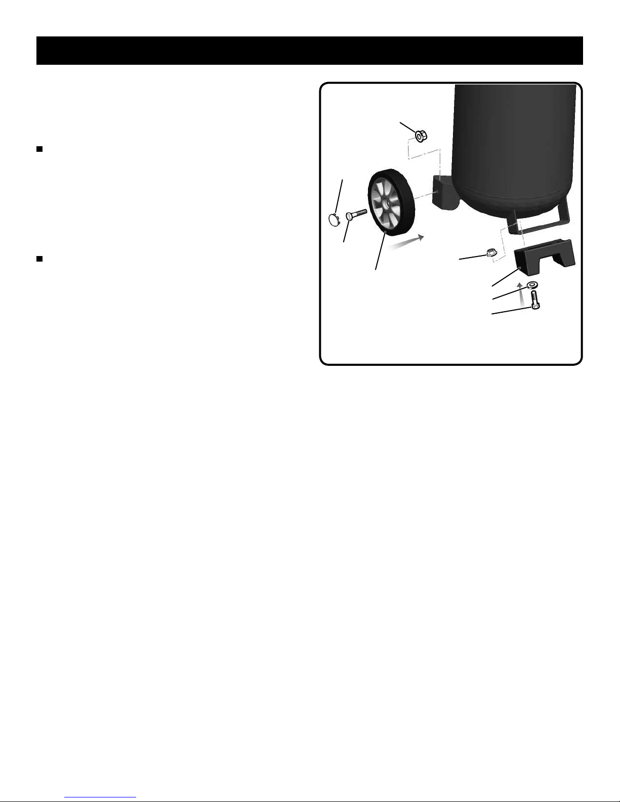
ASSEMBLY
ASSEMBLING THE RUBBER FOOT AND
WHEELS
See Figure 3.
Mount the rubber foot as shown in figure 3.
Tighten firmly with an open-end wrench (not included)
to secure it in position.
Rubber foot packing list:
– Screw 8 mm (2)
– Washer (2)
– Rubber Foot (1)
– Nut 8 mm (2)
Mount the wheels as shown in figure 3.
Tighten firmly with an open-end wrench (not included)
to secure the wheels in position.
Wheel packing list:
– Screw 10 mm (2)
– Wheel (2)
– Nut 10 mm (2)
– Wheel Plug (2) Fig. 3
WHEEL
SCREW
10mm NUT 8mm
NUT 10mm
SCREW 8mm
WHEEL
PLUG
RUBBER FOOT
WASHER

13
ASSEMBLY
WARNING:
Do not attach any tools to the open end of the hose until
start-up has been completed.
ATTACHING HOSE
See Figure 6.
Make sure the air compressor is off and unplugged.
Rotate pressure regulator knob fully counterclockwise.
Insert the hose into the quick coupler already installed
on the compressor (Fig. 6).
Firmly grasp the open end of the hose; hold facing
away from yourself and others.
BREAKING IN THE PUMP
See Figure 4 - 5.
Check and tighten all bolts, fittings, etc.
Turn the pressure regulator knob fully clockwise to
open the air flow.
Place the switch in the OFF (O) position and plug in the
power cord.
Open the drain valve completely.
Turn the air compress ON ( l ) and run the air
compressor for 10 minutes to break in pump parts.
Place the switch in the OFF (O) position.
Close the drain valve.
ASSEMBLY
TANK
PRESSURE
GAUGE
QUICK
COUPLER
PRESSURE
REGULATOR
KNOB
SAFETY
VALVE
ON/OFF
SWITCH
Fig. 4
DRAIN VALVE Fig. 5
QUICK
COUPLER
HOSE
Fig. 6
REGULATOR
PRESSURE
GAUGE

14
OPERATION
Fig. 8
COIL HOSE WITH QUICK
COUPLER ATTACHED
PNEUMATIC
TOOL
(not included)
MALE QUICK-
CONNECT PLUG
WARNING:
Always wear safety goggles or safety glasses with
side shields when operating power tools. Failure to do
so could result in objects being thrown into your eyes
resulting in possible serious injury.
WARNING:
Do not allow familiarity with tools to make you careless.
Remember that a careless fraction of a second is
sufficient to inflict serious injury.
CAUTION:
Do not use in an environment that is dusty or otherwise
contaminated. Using the air compressor in this type of
environment may cause damage to the unit.
WARNING:
Always ensure the switch is in the OFF (O) position and the
regulator pressure gauge reads zero before changing air
tools or disconnecting the hose from the air outlet. Failure
to do so could result in possible serious personal injury.
APPLICATIONS
Air compressors are utilized in a variety of air system
applications. Match hoses, connectors, air tools, and
accessories to the capabilities of the air compressor.
You may use this tool for purposes listed below:
Operating some air-powered tools.
Inflating tires, air beds, sports equipment, etc.
USING THE AIR COMPRESSOR
See Figure 7 - 8.
Ensure tank drain valve is closed (see Fig. 7).
Ensure ON/OFF power switch is in the OFF (O) position
and air compressor is unplugged (see Fig. 7).
Ensure Pressure Regulator Knob is turned fully
counterclockwise (see Fig. 7).
If not already installed, attach hose to compressor.
Connect air powered tools to air hose by inserting the
male quick-connect plug to the quick-coupler at the end
of the coil hose (see Fig. 8).
Connect the power cord to the power supply.
Turn the switch ON (I).
Rotate pressure regulator knob to desired line
pressure. Turning the knob clockwise increases
air pressure at the outlet; turning counterclockwise
reduces air pressure at the outlet.
NOTE:
Before connecting or disconnecting air tools turn
the regulator knob counter-clockwise to stop the flow of air.
Following all safety precautions in this manual and the
manufacturer’s instructions in the air tool manual, you
may now proceed to use your air-powered tool.
If using an inflation accessory with a quick-connect
fitting, control the amount of air flow with the pressure
regulator knob. Turning the knob fully counter-clockwise
will completely stop the flow of air.
NOTE: Always use the minimum amount of pressure
necessary for your application. Using a higher pressure
than needed will drain air from the tank more rapidly
and cause the unit to cycle on more frequently.
When finished, always drain the tank and unplug the unit.
Never leave the unit plugged in and/or running
unattended.
WARNING:
Check the air tool manual to insure the correct air pressure
regulator setting for optimum operation of your air tools. If you
are using an air tool not originally included with the air tool kit
suppliedwiththisaircompressor, your tool may require more air
consumption than this air compressor is designed to supply.
Always read your air tool owner’s manual to match the correct
air supply to your air tool to avoid damage to the tool or risk of
personal injury.
ON/OFF
POWER
SWITCH
PRESSURE
REGULATOR
KNOB
DRAIN
VALVE
Fig. 7
15
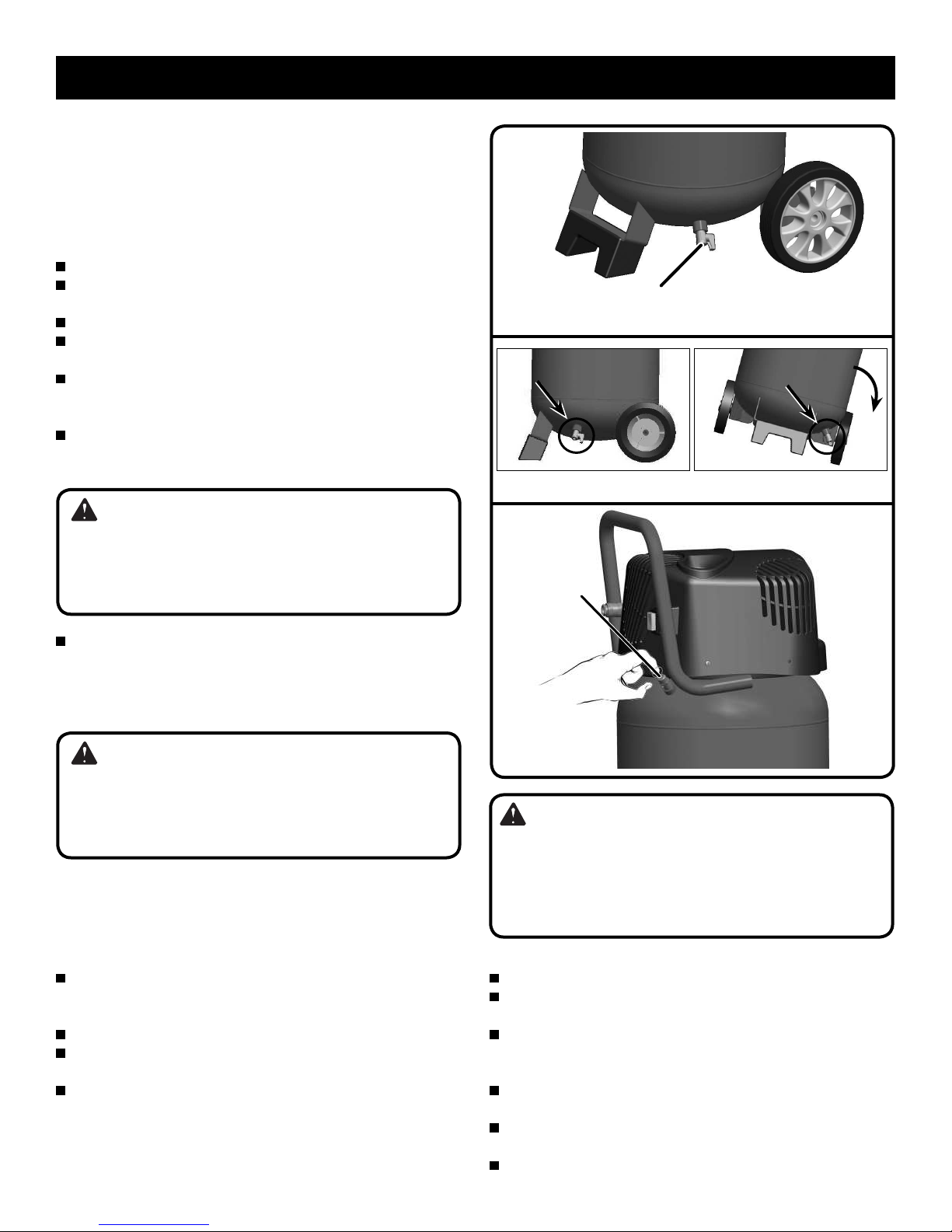
DRAINING THE TANK
See Figure 9 - 10.
To help prevent tank corrosion and keep moisture out of
the air used, the tank of the compressor should be drained
daily.
A correct use of the drain valve:
Verify that the compressor is turned off.
Holding the handle, tilt the compressor toward the drain
valve so that it’s set in a lower position.
Open the drain valve completely.
Keep the compressor tilted (figure 10) until all moisture
has been removed.
Drain moisture from tank into a suitable container.
NOTE: Condensate is a pollution material and should
be disposed of in compliance with local regulations.
If drain valve is clogged, release all air pressure by
pulling the safety valve. Remove and clean valve, then
reinstall.
Turn off drain valve until completely closed.
CHECKING THE SAFETY VALVE
See Figure 11.
The safety valve will automatically release air if the air
receiver pressure exceeds the preset maximum. The valve
should be checked before each day of use by pulling the
ring by hand.
Turn the air compressor on and allow the tank to
fill. The compressor will shut off when the pressure
reaches the preset maximum.
Turn the air compressor off.
Pull the ring on the safety valve to release air for twenty
seconds.
Release the ring. Air will stop escaping when the ring
is released at approximately 20 psi. Any continued
loss of air after releasing the safety valve ring indicates
a problem with the safety valve. Discontinue use
and seek service before continued use of the air
compressor.
OPERATION
WARNING:
Unplug the air compressor and release all air from
the tank before servicing. Failure to depressurize tank
before attempting to remove valve may cause serious
personal injury.
WARNING:
Do not attempt to tamper with safety valve. Anything
loosened from this device could fly up and hit you.
Failure to heed this warning could result in death or
serious personal injury.
SAFETY
VALVE
Fig. 11
DRAIN VALVE Fig. 9
Fig. 10
END OF OPERATION/STORAGE
Turn ON/OFF power switch to the OFF (O) position.
Unplug power cord from wall outlet and wrap around handle
area to prevent damage when not in use.
Wearing safety glasses drain tank of air by pulling the ring on
the safety valve. Use other hand to deflect fast moving air from
being directed toward your face.
Drain tank of condensation by opening drain valve on bottom of
tank. Tank pressure should be below 10 psi when draining tank.
Air hose should be disconnected from compressor and hung
open ends down to allow any moisture to drain.
Compressor and hose should be stored in a cool, dry place.
(Rotate drain valve right to open)
WARNING:
If air leaks after the ring has been released, or if the
valve is stuck and cannot be actuated by the ring,
Do Not use the air compressor until the safety valve
has been replaced. Use of the air compressor in this
condition could result in serious personal injury.

16
WARNING:
When servicing, use only identical Tool Shop
replacement parts. Use of any other parts may create a
hazard or cause product damage.
WARNING:
Always wear safety goggles or safety glasses with side
shields during power tool operation or when blowing
dust. If operation is dusty, also wear a dust mask.
WARNING:
Always release all pressure, disconnect from power
supply, and allow unit to cool to the touch before
cleaning or making repairs on the air compressor.
MAINTENANCE
GENERAL MAINTENANCE
Humidity in the air causes condensate to form in the air
tank. This condensate should be drained daily and/or
every hour, using the instructions found in Draining the
Tank.
The safety valve automatically releases air if the air
receiver pressure exceeds the preset maximum. Check
the safety valve before each use following the instructions
found in Checking the Safety Valve.
Inspect the tank yearly for rust, pin holes, or other
imperfections that could cause it to become unsafe.
Avoid using solvents when cleaning plastic parts. Most
plastics are susceptible to damage from various types of
commercial solvents and may be damaged by their use.
Use clean cloths to remove dirt, dust, oil, grease, etc.
LUBRICATION
All the bearings in this tool are lubricated with a sufficient
amount of high grade lubricant for the life of the unit
under normal operating conditions. Therefore, no further
lubrication of the bearings is required.
WARNING:
Do not at any time let brake fluids, gasoline, petroleum-
based products, penetrating oils, etc., come in contact
with plastic parts. Chemical can damage, weaken or
destroy plastic which may result in serious personal
injury. Electric tools used on fiberglass material, wall-
board, spackling compounds, or plaster are subject
to accelerated wear and possible premature failure
because the fiberglass chips and grindings are highly
abrasive to bearings, brushes, commutators, etc.
Consequently, we do not recommend using this tool for
extended work on these type of materials. However, if
you do work with any of these materials, it is extremely
important to clean the tool using compressed air.
OVERLOAD PROTECTOR
This air compressor is equipped with a thermal overload
device which will turn the air compressor off automatically,
if the air compressor becomes overheated. If the motor
turns OFF repeatedly, check for the following possible
causes first: Low Voltage from the outlet. Lack of proper
ventilation or outside air or room temperature too high.
Extension cord too long or wrong gauge wire used.
To reset the air compressor:
Turn the air compressor off.
Unplug the air compressor, and allow it to cool for 30
minutes.
Plug the air compressor into an approved outlet.
Turn the air compressor on.
OPERATION
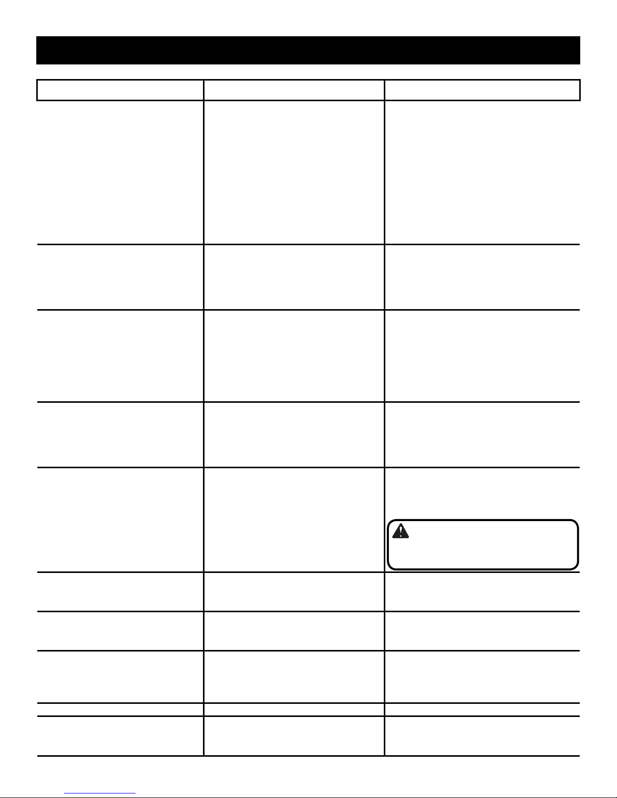
17
Problem Possible Cause Solution
Compressor will not run Tank has sufficient pressure.
No electrical power.
Blown stop/house fuse.
Tripped shop/home breaker.
Thermal overload open.
Loss of power or overheating.
Pressure switch is bad.
Compressor will turn on when tank
pressure drops to cut-in pressure.
Check to be sure unit is plugged in.
Replace shop/house fuse.
Reset shop/home breaker, determine why
problem happened.
First unplugged the compressor and
wait until it becomes cool. After that
compressor can be used.
Check for proper use of extension cord.
Replace pressure switch.
Motor hums but cannot run or runs
slowly Low voltage.
Wrong gauge wire or length of
extension cord.
Shorted or open motor winding.
Defective check valve or unloader.
Check with voltmeter.
Check for proper gauge wire and cord
length.
Take compressor to service center.
Take compressor to service center.
Fuses blow/circuit breaker trips
repeatedly Incorrect size fuse, circuit overload.
Wrong gauge wire or length of
extension cord.
Defective check valve or unloader.
Check for proper fuse, use time-
delay fuse, disconnect other electrical
appliances from circuit or operate
compressor on its own branch circuit.
Check for proper gauge wire and cord
length.
Take compressor to service center.
Thermal overload protector cuts out
repeatedly Low voltage.
Lack of proper ventilation/room
temperature too high.
Wrong gauge wire or length of
extension cord.
Check with voltmeter.
Move compressor to well-ventilated area.
Check for proper gauge wire and cord
length.
Air receiver pressure drops when
compressors shuts off Loose connections (fittings, tubing,
etc.).
Loose drain valve.
Check valve leaking.
Check all connections with soap and
water solution and tighten.
Tighten drain valve.
Take compressor to service center.
Excessive moisture in discharge air Excessive water in air tank.
High humidity. Drain tank.
Move to area of less humidity; use air line
filter.
Air leaking Loose or improperly sealed hose
connection.
Broken or damaged air hose.
Ensure connections are sealed with
thread sealing tape and tightened.
Replace air hose.
Compressor runs continuously Tank drain valve open.
Defective pressure switch.
Excessive usage.
Ensure tank drain valve is closed.
Take compressor to service center.
Decrease air usage; compressor not large
enough for tool’s requirement.
Compressor vibrates Loose mounting bolts. Tighten mounting bolts.
Air output lower than normal Broken inlet valves.
Connections leaking. Take compressor to service center.
Apply thread sealing tape to fitting and
tighten.
WARNING:
Do not disassemble check valve with air
in tank - bleed tank.
TROUBLESHOOTING
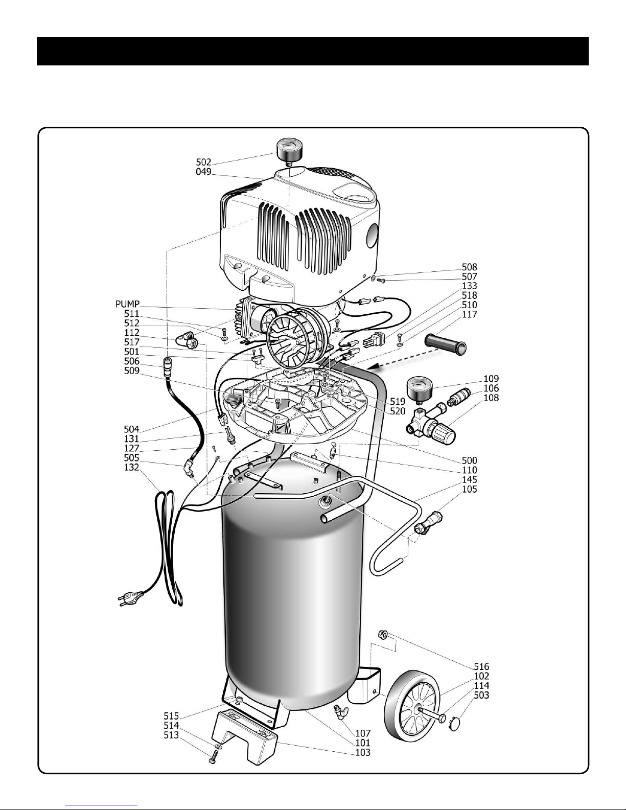
18
REPLACEMENT PARTS LIST
PARTS DIAGRAM − AIR COMPRESSOR

19
REPLACEMENT PARTS LIST
AIR COMPRESSOR PARTS LIST − MODEL NO. TS11OL227
The model number will be found on a plate attached to air tank. Always mention the model number in all
correspondence regarding your PORTABLE AIR COMPRESSOR or when ordering replacement parts.
KEY NO. CODE DESCRIPTION QTY
049 9038571 SEMIPLASTIC COVER UPPER...................................................................1
101 9413382035 TANK 12 GAL VERTICAL.............................................................................1
102 9042039 WHEEL.........................................................................................................2
103 9038481 RUBBER FOOT............................................................................................1
105 9048062 CHECK VALVE .............................................................................................1
106 9047061 QUICK COUPLING.......................................................................................1
107 9047084 DRAIN VALVE ..............................................................................................1
108 9051155 PRESSURE REDUCER ...............................................................................1
109 9052127 GAUGE.........................................................................................................1
110 9049105 SAFETY VALVE............................................................................................1
112 9050521 ELBOW.........................................................................................................1
114 9011049 WHEEL PIN ..................................................................................................2
117 9038408 RUBBER HANDLE .......................................................................................1
127 9270048 RILSAN PIPE........................................................................................... 1,15 ft
131 9063200 PRESSURE SWITCH...................................................................................1
132 9065680 CORD WITH PLUG ......................................................................................1
133 9414765 POWER SWITCH.........................................................................................1
145 9043345 SENDING PIPE ............................................................................................1
500 9038570 SEMIPLASTIC COVER LOWER..................................................................1
501 9064788 LOCK CABLE ...............................................................................................1
502 9414744 GAUGE.........................................................................................................1
503 9038402 WHEEL PLUG ..............................................................................................2
504 9064815 WIRING ........................................................................................................1
505 9050565 ELBOW.........................................................................................................1
506 9050566 CONNECTOR STRAIGHT ...........................................................................1
507 9142803 SCREW PARKER 4,2x22 .............................................................................4
508 9131655 WASHER D5 ................................................................................................4
509 9414746 SCREW M6x20 WITH WASHER..................................................................1
510 9131520 WASHER D6 ................................................................................................3
511 9101976 SCREW M6x15.............................................................................................3
512 9131641 WASHER D6 ................................................................................................3
513 9412230 SCREW M8x50.............................................................................................2
514 9131112 WASHER D8 ................................................................................................2
515 9122333 NUT M8 ........................................................................................................2
516 9122362 NUT M10 ......................................................................................................2
517 9142241 SCREW PARKER 4,2x16 .............................................................................2
518 9101244 SCREW M6x20.............................................................................................3
519 9104024 SCREW M5x16.............................................................................................2
520 9131126 WASHER D5,5 .............................................................................................2
PUMP C700062 PUMP OL227 120/60....................................................................................1

20
REPLACEMENT PARTS LIST
PARTS DIAGRAM − PUMP UNIT
Table of contents
Other Toolshop Air Compressor manuals


