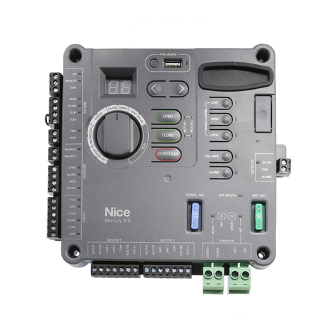
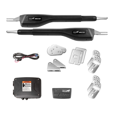
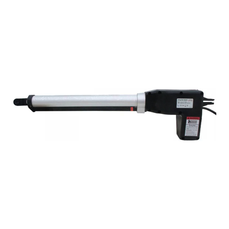
Toors BFT ARGO User manual

INSTALLATION MANUAL
INSTRUCTIONS D’INSTALLATION
MONTAGEANLEITUNG
MONTAGEHANDLEIDING
INSTRUKCJA INSTALACJI
РУКОВОДСТВО ПО МОНТАЖУ
MONTÁŽNÍ NÁVOD
ECO drive
www.loading-systems.com T09-080-20-0051
www.toors.com T09-080-20-0055
BFT ARGO

INSTALLER WARNINGS
Anything that is not explicitly provided for in the installation ma-
nual is not allowed. The operator’s proper operation can only be
guaranteed if the information given is complied with. The Firm shall
not be answerable for damage caused by failure to comply with the
instructions featured herein.
Whilewewillnotaltertheproduct’sessentialfeatures,theFirmreserves
the right, at any time, to make those changes deemed opportune to
improve the product from a technical, design or commercial point of
view, and will not be required to update this publication accordingly.
WARNING! Important safety instructions. Carefully read and comply with
all the warnings and instructions that come with the product as incorrect
installationcancauseinjurytopeopleandanimalsanddamagetoproperty.
Thewarningsandinstructionsgiveimportantinformationregardingsafety,
installation,use andmaintenance. Keephold ofinstructions so that you can
GENERAL SAFETY
This product has been designed and built solely for the purpose indicated herein.
Uses other than those indicated herein might cause damage to the product and
create a hazard.
-Theunitsmakingupthemachineanditsinstallationmustmeettherequirements
of the following European Directives, where applicable: 2014/30/EC, 2014/35/
EC, 2006/42/EC, 2011/305/EC, 99/05/EC and later amendments. For all countries
outside the EEC, it is advisable to comply with the standards mentioned, in ad-
dition to any national standards in force, to achieve a good level of safety.
-The Manufacturer of this product (hereinafter referred to as the“Firm”) disclaims
all responsibility resulting from improper use or any use other than that for
which the product has been designed, as indicated herein, as well as for failure
to apply Good Practice in the construction of entry systems (doors, gates, etc.)
and for deformation that could occur during use.
-
according to EN 12635), in compliance with Good Practice and current code.
-Before installing the product, make all structural changes required to produce
safety gaps and to provide protection from or isolate all crushing, shearing and
dragging hazard areas and danger zones in general in accordance with the
provisions of standards EN 12604 and 12453 or any local installation standards.
Check that the existing structure meets the necessary strength and stability
requirements.
-Before commencing installation, check the product for damage.
-The Firm is not responsible for failure to apply Good Practice in the construction
and maintenance of the doors, gates, etc. to be motorized, or for deformation
that might occur during use.
-Make sure the stated temperature range is compatible with the site in which the
automated system is due to be installed.
-
fumes or gas constitutes a serious safety hazard.
-Disconnect the electricity supply before performing any work on the system.
-Before connecting the power supply, make sure the product’s ratings match the
mains ratings and that a suitable residual current circuit breaker and overcurrent
protection device have been installed upline from the electrical system. Have
thermal-magnetic circuit breaker with a contact separation that provide full
disconnection under overvoltage category III conditions.
-Make sure that upline from the mains power supply there is a residual current
circuit breaker that trips at no more than 0.03A as well as any other equipment
required by code.
-Make sure the earth system has been installed correctly: earth all the metal parts
belonging to the entry system (doors, gates, etc.) and all parts of the system
featuring an earth terminal.
-Installation must be carried out using safety devices and controls that meet
standards EN 12978 and EN 12453.
-Impact forces can be reduced by using deformable edges.
-In the eventimpact forcesexceedthe values laid downbytherelevantstandards,
apply electro-sensitive or pressure-sensitive devices.
-Apply all safety devices (photocells, safety edges, etc.) required to keep the
area free of impact, crushing, dragging and shearing hazards. Bear in mind the
standards and directives in force, Good Practice criteria, intended use, the instal-
lation environment, the operating logic of the system and forces generated by
the automated system.
-Apply all signs required by current code to identify hazardous areas (residual
of standard EN 13241-1.
-Once installation is complete, apply a nameplate featuring the door/gate’s data.
-Thisproductcannotbeinstalledonleavesincorporatingdoors(unlessthemotor
can be activated only when the door is closed).
-If the automated system is installed at a height of less than 2.5 m or is accessible,
the electrical and mechanical parts must be suitably protected.
-For roller shutter automation only
1) The motor’s moving parts must be installed at a height greater than 2.5 m
2)The gearmotor must be installed in a segregated and suitably protected space
so that it cannot be reached without the aid of tools.
-
withindirect sight ofthepart beingcontrolledand,unlessthey are key operated,
must be installed at a height of at least 1.5 m and in a place where they cannot
be reached by the public.
-
attach a Warning sign to the structure.
-Attach a label near the operating device, in a permanent fashion, with informa-
tion on how to operate the automated system’s manual release.
-Make sure that, during operation, mechanical risks are avoided or relevant
crushed, caught or cut between the part being operated and surrounding parts.
-Once installation is complete, make sure the motor automation settings are
correct and that the safety and release systems are working properly.
-Only use original spare parts for any maintenance or repair work. The Firm dis-
claims all responsibility for the correct operation and safety of the automated
system if parts from other manufacturers are used.
-
explicitly authorized by the Firm.
-Instruct the system’s user on what residual risks may be encountered, on the
control systems that have been applied and on how to open the system manu-
ally in an emergency. give the user guide to the end user.
-Dispose of packaging materials (plastic, cardboard, polystyrene, etc.) in accord-
ance with the provisions of the laws in force. Keep nylon bags and polystyrene
out of reach of children.
WIRING
WARNING!For connectiontothemainspowersupply, use: a multicore cable with
a cross-sectional area of at least 5x1.5mm2or 4x1.5mm2when dealing with three-
phase power supplies or 3x1.5mm2for single-phase supplies (by way of example,
type H05RN-F cable can be used with a cross-sectional area of 4x1.5mm2).To con-
nect auxiliary equipment,usewires with across-sectional area of atleast 0.5 mm2.
- Only use pushbuttons with a capacity of 10A-250V or more.
- Wiresmustbesecuredwithadditionalfasteningneartheterminals(forexample,
using cable clamps) in order to keep live parts well separated from safety extra
low voltage parts.
- During installation, the power cable must be stripped to allow the earth wire
to be connected to the relevant terminal, while leaving the live wires as short
as possible. The earth wire must be the last to be pulled taut in the event the
cable’s fastening device comes loose.
WARNING! safety extra low voltage wires must be kept physically separate from
low voltage wires.
live parts.
CHECKING THE AUTOMATED SYSTEM AND MAINTENANCE
work, perform the following checks meticulously:
-Make sure all components are fastened securely.
-Check starting and stopping operations in the case of manual control.
-Check the logic for normal or personalized operation.
-For sliding gates only: check that the rack and pinion mesh correctly with 2 mm
of play along the full length of the rack; keep the track the gate slides on clean
and free of debris at all times.
-For sliding gates and doors only: make sure the gate’s running track is straight
and horizontal and that the wheels are strong enough to take the weight of the
gate.
-For cantilever sliding gates only: make sure there is no dipping or swinging
during operation.
-For swing gates only: make sure the leaves’ axis of rotation is perfectly vertical.
-For barriers only: before opening the door, the spring must be decompressed
(vertical boom).
-Check that all safety devices (photocells, safety edges, etc.) are working properly
and that the anti-crush safety device is set correctly, making sure that the force
of impact measured at the points provided for by standard EN 12445 is lower
than the value laid down by standard EN 12453.
-Impact forces can be reduced by using deformable edges.
-Make sure that the emergency operation works, where this feature is provided.
-Check opening and closing operations with the control devices applied.
-Check that electrical connections and cabling are intact, making extra sure that
insulating sheaths and cable glands are undamaged.
-While performing maintenance, clean the photocells’optics.
-When the automated system is out of service for any length of time, activate the
emergency release (see“EMERGENCY OPERATION”section) so that the operated
part is made idle, thus allowing the gate to be opened and closed manually.
-
If the power cord is damaged, it must be replaced by the manufacturer or their
-
mode, foresee mandatory maintenance at least every six months
-The maintenance described above must be repeated at least once yearly or at
shorter intervals where site or installation conditions make this necessary.
WARNING!
Remember that the drive is designed to make the gate/door easier to use and
will not solve problems as a result of defective or poorly performed installation
or lack of maintenance
SCRAPPING
Materials must be disposed of in accordance with the regulations in
force. Do not throw away your discarded equipment or used batteries
with household waste. You are responsible for taking all your waste
electrical and electronic equipment to a suitable recycling centre.
DISMANTLING
Iftheautomatedsystemisbeingdismantledinordertobereassembledatanother
site, you are required to:
-
-Remove the actuator from the base it is mounted on.
-Remove all the installation’s components.
-See to the replacement of any components that cannot be removed or happen
to be damaged.
DECLARATIONS OF CONFORMITY CAN BE FOUND AT http://www.bft-
automation.com/CE
INSTRUCTIONS FORUSE AND ASSEMBLY CAN BEFOUND INTHEDOWN-
LOAD SECTION.
- 2 -

ATTENTION ! Instructions de sécurité importantes. Veuillez lire et suivre
attentivement tous les avertissements et toutes les instructions fournis
avec le produit sachant qu’une installation incorrecte peut provoquer des
préjudices aux personnes, aux animaux ou aux biens. Les avertissements
fournissentdesindicationsimportantesconcernantlasécurité,l’installation,
l’utilisationetl’entretien.Veuillezconserverlesinstructionspourlesjoindre
au dossier technique et pour d’ultérieures consultations.
SECURITE GÉNÉRALE
Ce produit a été conçu et réalisé exclusivement pour l’usage indiqué dans cette
documentation. Tout usage autre que celui indiqué risque d’endommager le
produit et d’être une source de danger.
-Les éléments qui composent l’appareil et le montage doivent être conformes
aux Directives Européennes suivantes : 2014/30/CE, 2014/35/CE, 2006/42/CE,
-
partenant pas à la CEE, il est conseillé de respecter également les normes ci-
de sécurité.
-Le Fabricant de ce produit (par la suite « le Fabricant ») décline toute respon-
dans la présente documentation, de l’inobservation de la bonne technique de
construction des huisseries (portes, portails, etc.) et des déformations pouvant
apparaître à l’usage. -
nel, conformément à EN12635), dans le respect de la bonne technique et des
normes en vigueur.
-
nécessaires pour réaliser les butées de sécurité et la protection ou ségréga-
tion de toutes les zones présentant un risque d’écrasement, de cisaillement,
d’entraînement ou autre, conformément aux normes EN 12604 et 12453 ou les
-
-Le fabricant décline toute responsabilité en cas d’inobservation de la bonne
technique de construction et d’entretien des huisseries motorisées, ainsi que
de déformations survenant en cours d’utilisation.
-
à l’installation de l’automatisation.
-Ne pas installer ce produit dans une atmosphère explosive: la présence de gaz
-Mettre hors tensions l’installation avant d’accomplir une quelconque interven-
tion. Déconnecter également les batteries tampon éventuellement présentes.
- -
tion correspondent à celles du secteur et s’il y a en amont de l’installation élec-
trique un disjoncteur et une protection adéquats contre la surintensité. Pré-
voyez sur le réseau d’alimentation de l’automatisation un interrupteur ou un
magnétothermique omnipolaire permettant de procéder à une déconnexion
totale dans les conditions de la catégorie de surtension III.
-
ne dépasse pas 0,03A et les prescriptions des règlements en vigueur.
-
toutes les parties métalliques de la fermeture (portes, portails, etc..) et tous les
composants de l’installation munis de borne de terre.
-L’installation doit être équipée de dispositifs de sécurité et de commandes
conformes aux normes EN 12978 et EN12453.
-Les forces de choc peuvent être réduites à l’aide de rebords déformables.
-Si les forces de choc dépassent les valeurs prévues par les normes, appliquer
des dispositifs électrosensibles ou sensibles à la pression.
-Appliquer tous les dispositifs de sécurité (photocellules, linteaux sensibles,
etc..) nécessaires pour protéger la zone contre les risques de choc, d’écrase-
ment, d’entraînement ou de cisaillement. Tenir compte des règlements et des
directives en vigueur, des critères de bonne technique, de l’utilisation, de l’envi-
ronnement de l’installation, de la logique de fonctionnement du système et
des forces développées par l’automatisation.
-Appliquer les signaux prévus par les règlements en vigueur pour indiquer les
zones de danger (risques résiduels). Toutes les installations doivent être identi-
-
portail.
-Ce produit ne peut pas être installé sur des vantaux munis de portes (à moins
que le moteur ne puisse être actionné qu’avec la prote fermée).
bSi l’automatisation est installée à une hauteur inférieure à 2,5 m ou si elle est
accessible, il est indispensable de garantir un degré de protection adapté aux
parties électriques et mécaniques.
-Uniquement pour les automatisations de rideaux
1) Les parties en mouvement du moteur doivent être installées à plus de 2,5
mètres de hauteur au-dessus du sol ou de toute autre niveau servant à y accéder.
2) Le motoréducteur doit être installé dans un espace enfermé et muni de pro-
tection de façon à ce qu’il ne soit accessible qu’avec un outil.
--
sentent pas une source de danger et qu’elles soient éloignées des parties
mobiles. En particulier les commandes à homme présent doivent être visibles
directement de la partie guidée et- à moins qu’il n’y ait une clé, se trouver à 1,5 m
minimum de hauteur de façon à être inaccessibles au public.
-Appliquer au moins un dispositif de signalement lumineux (clignotant) visible,
-Fixer, à proximité de l’organe de manœuvre et de façon permanente, une éti-
quette sur le fonctionnement du déverrouillage manuel de l’automatisation.
-S’assurer que soient évités pendant la manœuvre les risques mécaniques et, en
particulier, l’écrasement, l’entraînement et le cisaillement par la partie guidée
et les parties voisines.
-
Une fois l’installation accomplie, s’assurer que le réglage du moteur est correct et
que les systèmes de protection et de déverrouillage fonctionnement correctement.
-Utiliser exclusivement des pièces détachées originales pour les opérations
d’entretien ou les réparations. Le Fabricant décline toute responsabilité quant
à la sécurité et au bon fonctionnement de l’automatisation en cas d’utilisation
de composants d’autres Fabricants.
- -
tion expresse du Fabricant.
-Informer l’utilisateur de l’installation sur les risques résiduels éventuels, sur les
systèmes de commande appliqués et sur la façon de procéder à l’ouverture
-Eliminer les matériaux d’emballage (plastique, carton, polystyrène, etc.) confor-
Tout ce qui n’est pas expressément prévu dans le manuel de montage
est interdit. Le bon fonctionnement de l’appareil n’est garanti que si
les données indiquées sont respectées. Le Fabricant ne répond pas des
dommages provoqués par l’inobservation des indications données
dans ce manuel.
En laissant inaltérées les caractéristiques essentielles de l’appareil,
-
cations qu’elle jugera opportunes pour améliorer le produit du point
de vue technique, commercial et de sa construction, sans s’engager à
mettre à jour la présente publication.
AVERTISSEMENTS POUR LE MONTEUR
mément aux normes en vigueur. Ne pas laisser les sachets en plastique et la
mousse de polystyrène à la portée des enfants.
CONNEXIONS
ATTENTION ! Pour le branchement sur le secteur, utiliser un câble multipolaire
ayant une section minimum de 5x1,5mm
2
ou de 4x1,5mm
2
pour alimentation tri-
phasée ou de 3x1,5mm
2
pour alimentation monophasée (par exemple, le câble
peut être du type H05RN-F avec une section de 4x1,5mm
2
). Pour le branchement
des auxiliaires, utiliser des conducteurs de 0,5 mm
2
de section minimum.
-Utiliser exclusivement des touches ayant une portée supérieure ou égale à
10A-250V.
-
parties sous tension des parties sous très faible tension de sécurité.
-
-
cher le conducteur de terre sur la borne appropriée en laissant cependant les
conducteurs actifs aussi courts que possibles. Le conducteur de terre doit être
ATTENTION ! Les conducteurs à très faible tension de sécurité doivent être phy-
siquement séparés des conducteurs à basse tension.
-
ties sous tension.
VÉRIFICATION DE L’AUTOMATISATION ET ENTRETIEN
-
ment opérationnelle et pendant les interventions d’entretien:
-
-
manuelle.
-
- -
gnon est correct, avec un jeu de 2 mm le long de toute la crémaillère; le rail de
glissement doit être toujours propre et dépourvu de débris.
-
horizontal et si les roues sont en mesure de supporter le poids du portail.
-
l’absence d’abaissement ou d’oscillation pendant la manœuvre.
-
est parfaitement vertical.
-Uniquement pour les barrières: avant d’ouvrir le portillon le ressort doit être
déchargé (barre verticale).
-
Contrôler le bon fonctionnement de tous les dispositifs de sécurité (photocel-
lules, linteaux sensibles etc..) et le bon réglage du dispositif de sécurité anti-écra-
par la norme EN12445 est inférieure à celle indiquée par la norme EN12453.
-Les forces de choc peuvent être réduites à l’aide de rebords déformables.
-
- -
tifs de commande appliqués.
-
l’état des gaines isolantes et des presse-câbles.
-Pendant les opérations d’entretien, nettoyer les lentilles des photocellules.
-Pendant la période de mise hors service de l’automatisation, activer le déver-
rouillage d’urgence (cf. paragraphe MANŒUVRE D’URGENCE) de façon à libérer
la partie guidée et à pouvoir accomplir l’ouverture et la fermeture manuelles
due portail.
-Silecâbled’alimentationestendommagé,ildoitêtreremplacéparleconstructeur
risque.
-
-L’entretien décrit plus haut doit être répété au moins une fois par an ou plus
fréquemment si les caractéristiques du site ou de l’installation le demandent.
ATTENTION !
Ne pas oublier que la motorisation facilite l’utilisation du portail/de la porte
mais qu’elle ne résout pas les problèmes imputables à des défauts ou à des
erreurs de montage ou encore à l’absence d’entretien.
DÉMOLITION
Eliminez les matériaux en respectant les normes en vigueur. Ne jetez
ni les vieux appareils, ni les piles, ni les batteries usées avec les ordures
-
leur recyclage.
DÉMANTÈLEMENT
Si l’automatisation est démontée pour ensuite être remontée sur un autre site, il faut:
- Couper l’alimentation et débrancher toute l’installation électrique.
- Démonter tous les composants de l’installation.
- Remplacer les composants ne pouvant pas être retirés ou endommagés.
LES DÉCLARATIONS DE CONFORMITÉ PEUVENT ÊTRE CONSULTÉES SUR LE
SITE INTERNET http://www.bft-automation.com/CE
LES INSTRUCTIONS DE MONTAGE ET D’UTILISATION PEUVENT ÊTRE CON-
SULTÉES DANS LA SECTION DOWNLOAD/TÉLÉDÉCHARGEMENT.
- 3 -

ACHTUNG! Wichtige Hinweise zur Sicherheit. Bitte lesen und befolgen Sie
aufmerksam die Hinweise sowie die Bedienungsanleitung, die das Produkt
begleiten, denn eine falsche Installation des Produkts kann zu Verletzungen
von Menschen und Tieren sowie zu Sachschäden führen. Sie liefern wichtige
Hinweise zur Sicherheit, zur Installation, zur Benutzung und zur Wartung.
Bewahren Sie die Anweisungen auf, um sie der technischen Dokumentation
hinzuzufügen und sie später konsultieren zu können.
1) ALLGEMEINE SICHERHEIT
Dieses Produkt wurde ausschließlich für die in der vorliegenden Dokumentation
angegebeneVerwendungkonzipiertundgefertigt.AndereVerwendungenkönnen
zu Beschädigungen des Produkts sowie zu Gefahren führen.
-Die Konstruktionsmaterialien der Maschine und die Installation müssen wo an-
wendbar den folgenden EU-Richtlinien entsprechen: 2014/30, 2014/35, 2006/42,
2011/305, 99/05 sowie den nachfolgenden Abänderungen. In allen Ländern
außerhalb der Europäischen Union sollten außer den geltenden nationalen Be-
stimmungen auch die vorgenannten Normen zur Gewährleistung der Sicherheit
befolgt werden.
-
Die Firma, die dieses Produkt herstellt (im Folgenden die „Firma“) lehnt jegliche
Haftung für Schäden ab, sind zurückzuführen sind auf eine unsachgemäße Be-
nutzung, die von der in der vorliegenden Dokumentation verschieden ist, auf die
Nichtbeachtung des Prinzips der sachgerechten Ausführung bei den Türen, Toren
usw. oder Verformungen, die während der Benutzung auftreten können.
-DieInstallationmussvonFachpersonal(professionellerInstallateurgemäßEN12635)
unter Beachtung der Regeln der guten Technik sowie der geltenden Normen
vorgenommen werden.
-Nehmen Sie vor der Installation des Produkts allen strukturellen Änderungen der
Sicherheitselemente sowie der Schutz. Und Abtrennvorrichtungen aller Bereiche
mit Quetschungs- und Abtrenngefahr sowie allgemeinen Gefahren gemäß den
Bestimmungen der Normen EN 12604 und 12453 oder der eventuellen lokalen
Installationsnormen vor. Stellen Sie sicher, dass die gesamte Struktur die Anfor-
derungen an Robustheit und Stabilität erfüllt..
-Vor der Installation muss die Unversehrtheit des Produkts überprüft werden.
-
Die Firma haftet nicht für die Folgen der Nichtbeachtung der Regeln der gutenTechnik
beiderKonstruktion und derWartungder zu motorisierendenTür-und Fensterrahmen
sowie für Verformungen, die sich während der Benutzung ergeben.
-Stellen Sie bei der Installation sicher, dass das angegebene Temperaturintervall
mit dem Installationsort der Automatisierung kompatibel ist.
-Installieren Sie das Produkt nicht in einer explosionsgefährdeten Umgebung. Das Vor-
handensein von entzündlichen Gasen stellt eine große Gefahr für die Sicherheit dar.
-
-Stellen Sie vor der Ausführung des elektrischen Anschlusses sicher, dass die Daten
auf dem Typenschild mit denen des Stromnetzes übereinstimmen und, dass der
Überstromvorgeschaltetsind.SetzenSieindieStromversorgungderAutomatisie-
rung einen Schalter oder einen allpoligen thermomagnetischen Schalter ein, der
unter Überspannungsbedingungen der Kategorie III die vollständige Trennung
gestattet.
-
Normen entspricht.
-Stellen Sie sicher, dass die Anlage ordnungsgemäß geerdet wird: Schließen Sie
alle Metallteile der Schließvorrichtung (Türen, Tore usw.) und alle Komponenten
der Anlage an, die eine Erdungsklemme aufweisen.
-Die Installation muss unter Verwendung von Sicherheits- und Steuerungsvorrich-
tungenvorgenommenwerden,diederNormEN12978undEN12453entsprechen.
-Die Aufprallkräfte können durch die Verwendung von verformbaren Leisten
reduziert werden.
-
Aufprallkräfte die von den Normen vorgesehenen Werte überschreiten.
-
Wenden Sie alle Sicherheitsvorrichtungen (Fotozellen, Sensoren usw.) an, die zum
SchutzdesGefahrenbereichesgegenAufprall,Quetschung,ErfassungundAbtrennung
von Gliedmaßen erforderlich sind. Berücksichtigen Sie die geltenden Normen und
Richtlinien,dieRegelndergutenTechnik,dieEinsatzweise,dieInstallationsumgebung,
die Betriebsweise sowie die vom System entwickelten Kräfte.
-BringenSiedievondengeltendenNormenzurAusweisungvonGefahrenbereichen
(die Restrisiken) die vorgesehenen Signale an. Alle Installationen müssen wie von
-
Bringen Sie nach Abschluss der Installation einTypenschild an derTür bzw. am Tor an.
-Dieses Produkt kann nicht an Toren installiert werden, in die Türen integriert sind
(es sei denn, der Motor wird ausschließlich bei geschlossener Tür aktiviert).
-Fallsdie Automatisierungauf einer Höhevonweniger als 2,5minstalliert wirdoder
zugänglichist,musseinangemessenerSchutzderelektrischenundmechanischen
Bauteile gewährleistet werden.
-
Nur für Automatisierungen für Schieber
1) Die beweglichen Teile des Motors müssen in einer Höhe von mehr als 2,5 m über
demBodenoder jeder anderenEbeneinstalliert werden, diedenZuganggestatten
kann.
2) Der Getriebemotor in einem abgetrennten und geschützten Raum installiert
werden, der nur mithilfe von Werkzeug zugänglich ist.
-InstallierenSieallefeststehendenBedienelementeso,dasssiekeineGefahrenerzeu-
gen und fern von beweglichen Bauteilen. Insbesondere dieTotmannvorrichtungen
müssen mit direkter Sicht auf den geführten Teil positioniert werden und falls sie
keinenSchlüsselaufweisen,müssensieineinerHöhevonmindestens1,5minstalliert
werden, sodass sie für das Publikum zugänglich sind.
-
BringenSiezumindesteineoptischeAnzeigevorrichtung(Blinkleuchte)ingutsichtbarer
Position an und befestigen Sie außerdem ein Schild Achtung an der Struktur.
-Bringen Sie einen Aufkleber, der die Funktionsweise der manuellen Entsperrung
der Automatisierung angibt, in der Nähe des Manöverorgans an.
-Stellen Sie sicher, dass während des Manövers mechanische Risiken wie Quet-
schung, Abtrennung und Erfassung zwischen dem geführten Bauteil und dem
feststehenden Bauteil vermieden werden.
-Stellen Sie nach der Installation sicher, dass der Motor de Automatisierung richtig
eingestellt worden ist und, dass die Schutzsysteme den Betrieb ordnungsgemäß
blockieren.
-
Verwenden Sie bei allen Wartungs- und Reparaturarbeiten ausschließlich Originaler-
satzteile. Die Firma haftet nicht für die Sicherheit und den ordnungsgemäßen Betrieb
der Automatik, falls Komponenten von anderen Herstellern verwendet werden.
-Nehmen Sie keine Änderungen an den Komponenten der Automatik vor, die von
der Firma nicht ausdrücklich genehmigt werden.
-Unterweisen Sie die Benutzer der Anlage hinsichtlich der angewendeten Steue-
Sie das Handbuch dem Endanwender aus.
-Entsorgen Sie die Verpackungsmaterialien (Plastik, Karton, Styropor usw.) unter
Beachtung der geltenden Bestimmungen. Halten Sie Plastiktüten und Styropor
von Kindern fern.
ANSCHLÜSSE
ACHTUNG! Verwenden Sie für den Anschluss an das Stromnetz: ein mehradriges
zum Beispiel dem Typ H05RN-F mit Querschnitt von 4 x 1,5 mm2entsprechen).
Verwenden Sie für den Anschluss der Zusatzanlage Leiter mit einem Mindest-
querschnitt von 0,5 mm2.
-
Verwenden Sie ausschließlich Tasten mit einer Schaltleistung von mindestens 10 A – 250 V.
-Die Leiter müssen in der Nähe der Klemmen zusätzlich befestigt werden (zum
Beispiel mit Kabelbindern), um die spannungführenden Bauteile von den Bau-
teilen mit niedriger Sicherheitsspannung zu trennen.
DasNetzkabelmussbeiderInstallationsoabisoliertwerden,dassderErdungsleiter
an die entsprechende Klemme angeschlossen werden kann. Dabei sollten die
beiden anderen Leiter so kurz wie möglich gelassen werden. Der Erdungsleiter
muss der letzte sein, der sich löst, falls das Kabel Zug ausgesetzt wird.
ACHTUNG! Die Leiter mit sehr niedriger Sicherheitsspannung müssen von den
Leitern mit niedriger Spannung getrennt verlegt werden.
Der Zugang zu den spannungsführenden Bauteilen darf ausschließlich für Fach-
personal (professioneller Installateur) möglich sein.
ÜBERPRÜFUNG UND WARTUNG DER AUTOMATISIERUNG
Nehmen Sie vor der Inbetriebnahme der Automatisierung sowie während der
-Stellen Sie sicher, dass alle Komponenten sicher befestigt worden sind.
-Überprüfen Sie das Starten und das Anhalten mit manueller Steuerung.
-Überprüfen Sie die normale oder die individuell angepasste Funktionsweise.
-Nur für Schiebetore: stellen Sie sicher, dass die Zahnstange und das Ritzel mit
einem Spiel von 2 mm auf der gesamten Länge der Zahnstange ineinander
greifen; halten Sie die Gleitschiene immer sauber und frei von Schmutz.
-
NurfürSchiebetoreundSchiebetüren:Sicherstellen,dassdieGleitschienedesTors
gerade und horizontal ist und, dass die Räder dem Gewicht desTors angemessen
sind.
-Nur für hängende Schiebetore (Cantilever): Sicherstellen, dass während des
Manövers keine Absenkung und keine Oszillationen vorhanden sind.
-
vollkommen vertikal ist.
- -
tikale Schranke).
-
Überprüfen Sie den ordnungsgemäßen Betrieb aller Sicherheitsvorrichtungen
(Fotozellen,Tastleistenusw.)sowie die richtigeEinstellungder Quetschschutzvor-
richtung; überprüfen Sie dazu, ob derWert der Aufprallkraft, der von der Norm EN
12445 vorgeschrieben wird, unterhalb der Angaben in der Norm EN 12453 liegt.
-Die Aufprallkräfte können durch die Verwendung von verformbaren Leisten
reduziert werden.
-Überprüfen Sie die Funktionsweise des Notfallmanövers, falls vorgesehen.
- -
vorrichtungen.
-Überprüfen Sie die elektrischen Anschlüsse und die Verkabelung sowie insbe-
sondere den Zustand der Isolierungen und der Kabeldurchführungen.
-Nehmen SiewährendderWartungeine Reinigung der Linsen der Fotozellen vor.
-Aktivieren Sie während der Nichtbenutzung der Automatisierung der Notfal-
lentsperrung (siehe Abschnitt “NOTFALLMANÖVER”), um den geführten Teil in
-Falls das Netzkabel beschädigt ist, muss es vom Hersteller, von dessen Kunden-
Risiken zu vermeiden.
-
nicht überprüftem Anschluss wird eine obbligatorischeWartung mit zumindest
halbjährlicher Frequenz vorgeschrieben.
- Die so wie oben beschriebene Wartung muss mit einer mindestens jährlichen
Regelmäßigkeit oder kürzeren Zeitintervallen wiederholt werden, falls die
Eigenschaften des Installationsortes dies verlangen sollten.
ACHTUNG!
Die Motorisierung dient zur Vereinfachung der Benutzung des Tors bzw. der Tür
und sie löst keine Installations- oder Wartungsmängel.
VERSCHROTTUNG
Die Entsorgung der Materialien muss unter Beachtung der geltenden
Normenerfolgen.BittewerfenSieIhrAltgerätoder die leerenBatterien
nicht in den Haushaltsabfall. Sie sind verantwortlich für die ordnungs-
gemäße Entsorgung Ihrer elektrischen oder elektronischen Altgeräte
ENTSORGUNG
Falls die Automatisierung ausgebaut wird, um an einem anderen Ort wieder
eingebaut zu werden, muss Folgendes beachtet werden:
-UnterbrechenSiedieStromversorgungundklemmenSiediegesamteelektrische
Anlage ab.
-Entfernen Sie den Trieb von der Befestigungsbasis.
-Bauen Sie sämtliche Komponenten der Installation ab.
-Nehmen Sie die Ersetzung der Bauteile vor, die nicht ausgebaut werden können
oder beschädigt sind.
Alles,wasimInstallationshandbuchnichtausdrücklichvorgesehenist,ist
untersagt. Der ordnungsgemäße Betrieb des Triebs kann nur garantiert
werden, wenn alle angegebenen Daten eingehalten werden. Die Firma
haftet nicht für Schäden, die auf die Nichtbeachtung der Hinweise im
vorliegenden Handbuch zurückzuführen sind.
Unter Beibehaltung der wesentlichen Eigenschaften des Produktes
vorliegenden Handbuches Änderungen zur technischen, konstruktiven
oder handelstechnischen Verbesserung vornehmen.
HINWEISE FÜR DEN INSTALLATEUR
DIEKONFORMITÄTSERKLÄRUNGENKÖNNENAUFDERWEB-SITEhttp://www.
bft-automation.com/CE konsultiert werden.
DIE ANWEISUNGEN ZUR MONTAGE UND BENUTZUNG KÖNNEN IM DOWN-
LOAD-BEREICH KONSULTIERT WERDEN.
- 4 -

LET OP! Belangrijke veiligheidsinstructies. De waarschuwingen en de instructies
diemethetproduct meegeleverd worden zorgvuldig lezenenvolgen,aangezien
verkeerdeinstallatieschadeaanpersonen,dierenofvoorwerpenkanveroorzaken.
De waarschuwingen en de instructies geven belangrijke aanwijzingen over de
veiligheid, de installatie, het gebruik en het onderhoud. De instructies bewaren
om ze aan de technische folder toe te voegen voor toekomstige raadpleging.
ALGEMENE VEILIGHEID
Dit product is uitsluitend ontworpen en gebouwd voor het gebruik aangegeven
indeze documentatie. Soortengebruikanders dan hetgeenaangegeven,zouden
schade aan het product en gevaar kunnen veroorzaken.
-De constructie-elementen van de machine en de installatie moeten overeenkom-
stig de volgende Europese Richtlijnen zijn, indien toepasbaar: 2014/30/CE, 2014/35/
CE, 2006/42/CE, 2011/305/CE, 99/05/CE en daaropvolgende wijzigingen. Voor alle
landen buiten de EEG is het voor een goed veiligheidsniveau nuttig om naast de
nationaal geldende normen, ook de genoemde normen in acht te nemen.
-Het Bedrijf wijst iedere willekeurige verantwoordelijkheid af voortkomende uit een
verkeerd gebruik of een ander gebruik dan het voorbestemde gebruik en dat aan-
gegeven in deze documentatie, evenals uit het niet in acht nemen van het Goed
Gebruik bij de constructie van de sluitingen (deuren, hekken, etc..) en uit de vervor-
mingen die tijdens het gebruik zouden kunnen optreden.
- -
nele installateur, volgens EN12635), met inachtneming van het Goed Gebruik en de
geldende normen.
-Alvorens het product te installeren, alle structurele wijzigingen aanbrengen betref-
fende de verwezenlijking van de vrijboorden en de beveiliging of afscheiding van
alle zones met gevaar voor pletting, snijden, meeslepen en algemeen gevaar, vol-
gens hetgeen voorgeschreven wordt door de normen EN 12604 en 12453 of even-
tuele plaatselijke installatienormen. Controleren of de bestaande structuur over de
noodzakelijke vereisten beschikt wat betreft stevigheid en stabiliteit.
-
Alvorens te beginnen met de installatie, de goede toestand van het product controleren.
-Het bedrijf is niet verantwoordelijk voor het niet naleven van het Goed Gebruik bij
de constructie en het onderhoud van de te motoriseren kozijnen, en van de vervor-
mingen die zich tijdens het gebruik kunnen voordoen.
-Controleren of het opgegeven temperatuurinterval compatibel is met de plek be-
stemd voor de installatie van het automatiseringssysteem.
-Dit product niet in een explosieve omgeving installeren: de aanwezigheid van gas of
ontvlambare rookgassen vormt een ernstig gevaar voor de veiligheid.
-
De stroomvoorziening uitschakelen vóór wat voor werkzaamheden dan ook aan de
-
Voordat men de elektrische voeding aansluit, moet men controleren of de gegevens
op de plaat overeenstemmen met die van het elektriciteitsnet en of er stroomop-
geschikte bescherming tegen overstroom staat. Op het voedingsnet van het auto-
matiseringssysteem een omnipolaire (magneet)schakelaar voorzien waarmee een
volledige uitschakeling mogelijk is in de omstandigheden van overspanningscate-
gorie III.
-
Controleren of er zich aan het begin van het voedingsnet een aardlekschakelaar bevindt
die de drempel van max. 0,03A en de geldende normen niet overschrijdt.
-Controleren of het aardingssysteem correct is uitgevoerd: alle metalen delen van
de sluiting (deuren, hekken, etc.) en alle onderdelen van de installatie voorzien van
aardingsklemmen aarden.
-De installatie moet worden uitgevoerd met gebruik van veiligheidsinrichtingen en
bedieningen overeenkomstig EN 12978 en EN12453.
-De botsingskrachten kunnen verminderd worden door middel van het gebruik van
vervormbare randen.
-
In het geval dat de botsingskrachten de door de normen voorziene waarden over-
schrijden, inrichtingen aanbrengen die gevoelig zijn voor elektriciteit of druk.
-Alle veiligheidsinrichtingen (fotocellen, gevoelige randen, etc.) aanbrengen die
noodzakelijk zijn om het gebied te beschermen tegen gevaren voor botsing, plet-
ting, meeslepen en snijden. Rekening houden met de geldende normen en richtlij-
nen, de criteria van het Goed Gebruik, het gebruik, de installatieomgeving, de wer-
king van het systeem en de door het automatiseringssysteem ontwikkelde krachten.
-
De door de geldende normen voorziene signalen aanbrengen om de gevaarlijke zo-
nes aan te duiden (de restrisico’s). Iedere installatie moet op zichtbare wijze worden
-
aanbrengen.
-
Dit product mag niet worden geïnstalleerd op vleugels waarin deuren zijn opgeno-
men (tenzij de motor uitsluitend kan worden geactiveerd wanneer de deur dicht is).
-Als het automatiseringssysteem is geïnstalleerd op een hoogte van minder dan 2,5
m of als het toegankelijk is, is het noodzakelijk een passende beschermingsgraad
van de elektrische en mechanische delen te garanderen.
-Alleen voor automatiseringssystemen voor rolluiken
1) De bewegende delen van de motor moeten op een minimale hoogte van 2,5 m
boven de vloer of een ander niveau waar de toegang mogelijk is geïnstalleerd worden.
2) De reductiemotor moet in een afgescheiden ruimte geïnstalleerd worden voorzien
van een beveiliging zodat hij alleen met gebruik van gereedschap toegankelijk is.
-
Iedere willekeurige vaste bediening zo installeren, dat deze geen gevaar vormt en
ver van beweegbare delen is. In het bijzonder de bedieningen bij aanwezige persoon
moeten direct zichtbaar zijn vanaf het geleide deel, en, tenzij het gaat om bedieningen
met sleutel, moeten deze worden geïnstalleerd op een hoogte van minstens 1,5 m en
zodanig dat ze niet toegankelijk zijn voor het publiek.
-Minstens één signaleringsinrichting (knipperend) aanbrengen in een zichtbare posi-
tie, en daarnaast een bordje“Let op”aan de structuur bevestigen.
-Op permanente wijze een etiket aanbrengen met betrekking tot de werking van de
handmatige deblokkering van het automatiseringssysteem en dit in de buurt van de
manoeuvreringsinrichting aanbrengen.
-Zorg ervoor dat tijdens de manoeuvre de mechanische risico’s vermeden en bevei-
ligd worden en dan met name de botsing, de pletting, het meeslepen, het snijden
tussen geleide deel en omliggende delen.
-Na de installatie te hebben uitgevoerd, zich ervan verzekeren dat de instelling van
het automatiseringssysteem van de motor juist is uitgevoerd en dat de beveiligings-
en deblokkeringssystemen juist functioneren.
-
Uitsluitend originele reserveonderdelen gebruiken voor alle onderhouds- of repara-
tiewerkzaamheden. Het Bedrijf wijst iedere willekeurige verantwoordelijkheid af uit
veiligheidsredenen en vanwege de goede werking van het automatiseringssysteem,
als er onderdelen van andere fabrikanten gebruikt worden.
-Geen enkele wijziging uitvoeren aan de componenten van het automatiseringssys-
teem, indien niet uitdrukkelijk door het Bedrijf geautoriseerd.
-
De gebruiker van de installatie instructies geven wat betreft de restrisico’s, de toege-
paste bedieningssystemen en de uitvoering van de handmatige openingsmanoeuvre
in geval van nood: de gebruikershandleiding aan de eindgebruiker overhandigen.
Al hetgeen niet uitdrukkelijk voorzien is in de installatiehandleiding, is
niet toegestaan. De goede werking van de controller is alleen gegaran-
deerd, als de vermelde gegevens in acht worden genomen. Het bedrijf is
niet gehouden zich te verantwoorden voor de schade veroorzaakt door
het niet in acht nemen van de aanwijzingen vermeld in deze handleiding.
Terwijldehoofdkenmerkenvanhetproductongewijzigdblijven,behoudt
het Bedrijf zich het recht voor om op ieder willekeurig moment die wijzi-
gingen aan te brengen die zij geschikt acht om het product technisch,
constructiefencommercieelgezien teverbeteren,zonderdezepublicatie
te hoeven bijwerken.
WAARSCHUWINGEN VOOR DE INSTALLATEUR
-Verpakkingsmaterialen (plastic, karton, polystyrol, etc.) verwerken volgens hetgeen
voorzien is door de geldende normen. Nylon zakjes en polystyrol buiten bereik van
kinderen bewaren.
AANSLUITINGEN
LET OP! Gebruik voor de aansluiting op het netwerk: meeraderige kabel met een
doorsnede van min. 5x1,5 mm2of 4x1,5 mm2voor driefase voeding of 3x1,5 mm2
voor eenfase voeding (de kabel moet bijvoorbeeld van het type H05RN-F met
doorsnede 4x1,5 mm2zijn).Voor de aansluiting van de hulpapparatuur geleiders
gebruiken met een doorsnede van min. 0,5 mm2.
-
Uitsluitend drukknoppen gebruiken met een werkbelasting van min. 10A-250V.
- De geleiders moeten verbonden worden door een extra bevestiging in de buurt
van de klemmen (bijvoorbeeld met behulp van bandjes) om de delen onder
spanning duidelijk gescheiden te houden van de delen met zeer lage veiligheids-
spanning.
- Tijdens de installatie moet de stroomtoevoerkabel van zijn bekleding ontdaan
worden, zodat de aansluiting van de aardgeleider op de geschikte klem mogelijk
wordt, terwijl de actieve geleiders echter zo kort mogelijk gelaten worden. De
aardgeleider moet de laatste zijn die gerekt wordt in geval van losraken van de
bevestigingsinrichting van de kabel.
OPGELET! de geleiders met zeer lage veiligheidsspanning moeten fysiek geschei-
den worden van de geleiders met lage spanning.
De toegang tot de delen onder spanning mag uitsluitend mogelijk zijn voor het
CONTROLEVAN HET AUTOMATISERINGSSYSTEEM EN ONDERHOUD
Alvorens het automatiseringssysteem in werking te stellen, en tijdens de onder-
houdswerkzaamheden, nauwgezet het volgende nagaan:
-controleren of alle onderdelen stevig zijn bevestigd;
-
de opstart- en stophandelingen in het geval van de handmatige besturing controle-
ren;
-de normale of gepersonaliseerde werking controleren.
-Alleen voor schuifhekken: de correcte ineengrijping tandheugel-rondselas met
een speling van 2 mm over de hele tandheugel controleren; de looprail altijd
schoon houden en vrij van afval.
-Alleen voor schuifhekken en –deuren: controleren of de glijrail recht en horizon-
taal is en of de wielen geschikt zijn voor het gewicht van het hek.
-Alleen voor hangende schuifhekken (Cantilever): controleren of het hek niet zakt
of trilt tijdens de manoeuvre.
-Alleen voor vleugelpoorten: controleren of de rotatie-as van de vleugels perfect
verticaal is.
-Alleen voor slagbomen: alvorens het deurtje te openen, moet de veer ontladen
zijn (slagboom verticaal).
-
De juiste werking van alle veiligheidsinrichtingen controleren (fotocellen, gevoe-
lige randen, etc.) en de correcte afstelling van de antibeklemmings-veiligheidsin-
richting door te controleren of de waarde van de botsingskracht gemeten in de
punten voorzien door de norm EN12445, lager is dan hetgeen aangegeven in de
norm EN 12453.
-De botsingskrachten kunnen verminderd worden door middel van het gebruik
van vervormbare randen.
-De functionaliteit van de noodmanoeuvre controleren, indien aanwezig.
-De openings- of sluitingshandeling met de aangebrachte bedieningsinrichtin-
gen controleren.
-De goede toestand van de elektrische aansluitingen en van de bekabelingen
controleren, met name de status van de isolatiekousen en de kabelleiders.
-Tijdens het onderhoud de reiniging van de optieken van de fotocellen uitvoeren.
-Voor de periode waarin het automatiseringssysteem buiten bedrijf is, de nood-
deblokkering activeren (zie paragraaf “NOODMANOEUVRE”) om het geleide deel
los te maken en zo de handmatige opening en sluiting van het hek mogelijk te
maken.
-Indien de voedingskabel beschadigd is, moet deze vervangen worden door de
fabrikant of door diens technische assistentiedienst of alleszins door een persoon
-Als er inrichtingen type “D” geïnstalleerd worden (zoals ged ieerd door
voorschrijven.
- Het onderhoud dat hierboven is beschreven moet minstens eenmaal per jaar of
vaker als de plaats of de installatie dit vereist, worden verricht.
LET OP!
Vergeet niet dat de motoraandrijving een gemak is bij het gebruik van het hek /
de poort en geen oplossing biedt voor problemen door defecten en installatiege-
breken of gebrek aan onderhoud.
SLOOP
De materialen moeten verwijderd worden met inachtneming van de
geldende normen. Uw niet meer gebruikte apparaat, de lege batterijen
of accu’s niet bij het huisvuil weggooien. U bent er verantwoordelijk voor
al uw afval van elektrische of elektronische apparatuur weg te brengen
naar een inzamelpunt voor de recycling ervan.
ONTMANTELING
In het geval dat het automatiseringssysteem gedemonteerd wordt om op een an-
dere plek opnieuw gemonteerd te worden, is het nodig:
-
De stroomvoorziening uit te schakelen en de hele elektrische installatie los te kop-
pelen.
-De actuator van de bevestigingsbasis te verwijderen.
-Alle onderdelen van de installatie te demonteren.
-In het geval dat enkele onderdelen niet verwijderd kunnen worden of bescha-
digd blijken te zijn, deze vervangen.
DE CONFORMITEITSVERKLARINGEN KUNNEN WORDEN INGEZIEN OP DE
WEBSITE http://www.bft-automation.com/CE
DE MONTAGE- EN GEBRUIKSAANWIJZINGEN KUNNEN WORDEN INGEZIEN
IN HET DEEL DOWNLOAD.
- 5 -

OSTRZEŻENIA DLA MONTERA
Wszelkie zagadnienia, które nie zostały wyraźnie przedstawione w
instrukcji montażu należy uznać za niedozwolone. Prawidłową pracę
urządzenia zapewnia wyłącznie przestrzeganie przedstawionych
danych. Producent nie odpowiada za szkody spowodowane nieprze-
strzeganiem zaleceń zawartych w niniejszej instrukcji.
Producent zastrzega sobie prawo do wprowadzenia w każdym mo-
konstrukcyjneihandloweproduktu,pozostawiającniezmienionejego
cechypodstawowe,bezkonieczności aktualizacjininiejszejpublikacji.
UWAGA! Ważne informacje dotyczące bezpieczeństwa. Należy przeczytać
i dokładnie stosować się do zaleceń oraz do instrukcji dołączonych do pro-
duktu,ponieważnieprawidłowaeksploatacjamożespowodowaćobrażenia
osób, zwierząt oraz uszkodzenie przedmiotów. Dostarczają one ważnych
wskazówek dotyczących bezpieczeństwa, montażu, eksploatacji oraz kon-
serwacji.Instrukcjenależy zachować w celuichdołączeniadodokumentacji
technicznej oraz do wglądu w przyszłości.
BEZPIECZEŃSTWO OGÓLNE
Niniejszy produkt został zaprojektowany i wykonany wyłącznie w celach użyt-
kowych przedstawionych w niniejszej dokumentacji. Sposoby eksploatacji
inne, niż omówione mogą być przyczyną uszkodzenia produktu oraz zagrażać
bezpieczeństwu.
-Elementy konstrukcyjne urządzenia oraz instalacja muszą spełniać wymogi
poniższych Dyrektyw Europejskich (jeżeli znajdują one zastosowanie): 2014/30/
WE,2014/35/WE,2006/42/WE,2011/305/WE,99/05/WEzpóźniejszymizmianami.
W celu zachowania odpowiedniego poziomu bezpieczeństwa stosowanie wy-
mienionych norm, oprócz obowiązujących przepisów krajowych, jest zalecane
również we wszystkich krajach nie należących do EWG.
-Producent niniejszego produktu (dalej „Producent”) uchyla się od wszelkiej
odpowiedzialności w przypadku nieprawidłowego lub niezgodnego z prze-
znaczeniem użytkowania opisanego w niniejszej dokumentacji, jak również w
przypadku niestosowania się do Zasad Technicznych podczas wykonywania
zamknięć (drzwi, bramy, itp.) oraz w przypadku deformacji, które mogą pojawić
się podczas eksploatacji.
-Montaż należy powierzyć osobom o odpowiednich umiejętnościach (zawodo-
wy monter, zgodnie z wymogami normy EN12635), które stosują się do Zasad
Technicznych oraz do obowiązujących przepisów.
- -
strukcyjne związane z wykonaniem zabezpieczeń oraz z ochroną lub oddziele-
niem wszystkich stref zagrażających zmiażdżeniem, przecięciem, wciągnięciem
i zagrożeniami ogólnymi, w myśl norm EN 12604 i 12453 lub ewentualnych,
miejscowych norm montażowych. Sprawdzić, czy istniejąca struktura spełnia
wymogi z zakresu wytrzymałości i stabilności.
-
Przed rozpoczęciem montażu należy sprawdzić, czy produkt nie jest uszkodzony.
-Producent nie ponosi odpowiedzialności za niestosowanie Zasad Techniki
podczas wykonywania i konserwacji napędzanych silnikowo zawiasów, ani za
odkształcenia, które mogą się pojawić podczas eksploatacji.
-Sprawdzić, czy zadeklarowany przedział temperatur jest zgodny z warunkami
panującymi w miejscu przeznaczonym do montażu automatyki.
-Nie instalować w środowisku wybuchowym: obecność gazu lub łatwopalnych
oparów stanowi poważne zagrożenie bezpieczeństwa.
-Przed przystąpieniem do wykonywania jakichkolwiek czynności na urządzeniu
należy odłączyć zasilanie elektryczne. Wyjąć również ewentualne baterie zapa-
sowe, jeżeli są.
-Przed podłączeniem zasilania elektrycznego sprawdzić, czy dane z tabliczki
znamionowej są zgodne z danymi sieci elektrycznej, oraz czy przed wejściem do
instalacjielektrycznejznajdujesięwyłącznikróżnicowo-prądowyorazodpowied-
nie zabezpieczenie przed przetężeniami. Sieć zasilająca automat powinna być
wyposażona w przełącznik lub wyłącznik instalacyjny umożliwiający całkowite
odłączenie w przypadku przepięcia kategorii III.
-Sprawdzić,czyprzedwejściemdosiecizasilaniaznajdujesięwyłącznikróżnicowo-
-prądowy o progu zadziałania nie wyższym niż 0,03A oraz spełniający wymogi
obowiązujących przepisów.
-Sprawdzić,czyuziemieniejestwykonanewprawidłowysposób:połączyćwszyst-
kie metalowe części zamknięcia (drzwi, bramy, itp.) oraz wszystkie komponenty
instalacji wyposażone w zacisk uziemiający.
-Podczas instalacji należy wykorzystać zabezpieczenia i sterowniki spełniające
wymogi norm EN 12978 i EN12453.
-Siłę uderzenia można zredukować przy pomocy odkształcających się listewek.
-Jeżeli siła uderzenia przekracza wartości przewidziane w przepisach, należy
zastosować elektroczułe lub wykrywające nacisk urządzenia.
-Zastosowaćwszystkiezabezpieczenia(fotokomórki,czułelistwy,itp.)niezbędne
doochronydanegoobszaru przeduderzeniem, przygnieceniem,wciągnięciem,
przecięciem.Należyuwzględnićobowiązująceprzepisyidyrektywy,zasadytech-
niczne, sposób eksploatacji, otoczenie montażowe, zasadę działania urządzenia
oraz siły wytwarzane przez automatykę.
-Zainstalowaćprzewidzianeobowiązującymprawemoznakowaniawyznaczające
strefyniebezpieczne(orazryzykoresztkowe).Każdeurządzenienależyoznakować
w sposób widoczny, zgodny z zaleceniami normy EN13241-1.
-
-
Tego produktu nie można instalować na skrzydłach, w których są wbudowane
przejścia (chyba że silnik jest uruchamiany wyłącznie przy zamkniętym przejściu).
-Jeżeli automatyczne urządzenie jest zainstalowane niżej niż 2,5 m, lub jeżeli
pozostaje dostępne, należy zapewnić odpowiedni stopień ochrony części elek-
trycznych i mechanicznych.
-Tylko bramy rolowane
1) Ruchome części silnika należy zainstalować na wysokości ponad 2,5 m od
chodnika lub od poziomu, z którego można uzyskać do nich dostęp.
2) Motoreduktor należy zainstalować w oddzielnym, zabezpieczonym miejscu,
tak aby dostęp do niego możliwy był tylko z użyciem narzędzi.
-Wszystkie nieruchome sterowniki należy zainstalować w takim miejscu, aby nie
stwarzać zagrożenia oraz z dala od ruchomych mechanizmów. W szczególności
sterowniki uruchamiane wyłącznie przez człowieka należy umieścić w miejscu
widocznym z miejsca obsługi i, z wyjątkiem sytuacji gdy są one wyposażone w
klucz, należy je zainstalować na wysokości co najmniej 1,5 m oraz tak, aby nie
były dostępne dla osób postronnych.
-Wwidocznymmiejscunależyzainstalowaćconajmniejjedensygnalizatorświetlny
(migający), a ponadto przymocować do struktury tabliczkę z napisem Uwaga.
-Po zakończeniu instalacji upewnić się, iż ustawienia pracy silnika są wykonane
prawidłowo, oraz iż systemy ochronne i odblokowujące działają prawidłowo.
-Podczas konserwacji i napraw należy stosować wyłącznie oryginalne części
zamienne. W przypadku zastosowania części innych producentów, Producent
uchyla się od wszelkiej odpowiedzialności z zakresu bezpieczeństwa i prawidło-
wego działania automatyki.
-
wyraził na to zgody.
-Przeszkolić użytkownika urządzenia w zakresie zastosowanych systemów ste-
rowania oraz z ręcznego otwierania awaryjnego. Przekazać instrukcję obsługi
użytkownikowi ostatecznemu.
-Materiałyopakowaniowe(plastik,karton,styropian,itp.)należyutylizowaćzgod-
nie z obowiązującymi przepisami. Nie zostawiać foliowych toreb ani styropianu
w miejscach dostępnych dla dzieci.
POŁĄCZENIA
UWAGA! W celu podłączenia do sieci należy zastosować kabel wielobiegunowy
o minimalnym przekroju 5x1,5mm2lub 4x1,5mm2dla zasilania trójfazowego lub
3x1,5mm2dla zasilania jednofazowego (przykładowo, może to być kabel typu
H05RN-F o przekroju 4x1.5mm2).W celu podłączenia obwodów pomocniczych
należy zastosować przewody o minimalnym przekroju 1mm2.
-Stosować wyłącznie przyciski o parametrach nie przekraczających 10A-250V.
-Przewody należy dodatkowo zamocować w pobliżu zacisków (na przykład przy
pomocy chomątek), aby wyraźnie rozdzielić części pod napięciem od części pod
najniższym napięciem bezpieczeństwa.
Podczas instalacji z kabla zasilającego należy ściągnąć osłonę, aby można było
połączyć przewód uziemiający z odpowiednim zaciskiem, a przewody robocze
powinnybyćjaknajkrótsze.Wprzypadkupoluzowaniamocowanakablaprzewód
uziemiający powinien naprężać się jako ostatni.
UWAGA!
odłączone od przewodów niskiego napięcia.
Dostęp do części pod napięciem mogą mieć wyłącznie osoby o odpowiednich
uprawnieniach (zawodowy monter).
PRZEGLĄD AUTOMATYKI I KONSERWACJA
Przed ostatecznym uruchomieniem automatyki oraz podczas wykonywania
czynności konserwacyjnych należy dokładnie wykonać poniższe czynności:
-Sprawdzić, czy wszystkie części są dokładnie umocowane.
-
Sprawdzić jak przebiega uruchamianie i zatrzymywanie w przypadku obsługi ręcznej.
-Sprawdzić kolejność działania w trybie zwykłym i z zastosowaniem ustawień
osobistych.
-Tylko w przypadku bram przesuwnych: sprawdzić, sprawdzić, czy zębatka pra-
widłowo zazębiła się z kołem zębatym, przy czym wzdłuż całej zębatki powinien
być luz ok. 2 mm; szynę przesuwną należy utrzymywać w czystości i usuwać
wszelkie zanieczyszczenia.
-Tylko dla bram i drzwi przesuwnych: sprawdzić, czy szyna prowadząca bramy
jest prosta, ustawiona poziomo, i czy kółka wytrzymają ciężar bramy.
-Tylkodlabramprzesuwnychzawieszanych(samonośnych):sprawdzić,czypodczas
wykonywania cyklu brama się nie obniża ani nie wykonuje ruchu wahadłowego.
-Tylko dla bram skrzydłowych: sprawdzić, czy oś obrotu skrzydeł jest idealnie
pionowa.
- Dotyczy szlabanów: przed otwarciem drzwiczek sprężyna nie powinna być
napięta (ramię ustawione pionowo).
-Sprawdzić, czy wszystkie zabezpieczenia działają prawidłowo (fotokomórki,
czułe listwy, itp.) oraz czy zabezpieczenie chroniące przed przygnieceniem jest
właściwie wyregulowane. W tym celu sprawdzić, czy siła uderzenia, zmierzona
wmiejscach przewidzianychnormą EN12445nie przekraczawartości podanych
w normie EN 12453.
-Siłę uderzenia można zredukować przy pomocy odkształcających się listewek.
-Sprawdzić, czy ręczne sterowanie awaryjne przebiega bez problemów (jeżeli
takie zastosowano).
-Sprawdzićotwieranieizamykanieprzy pomocy przeznaczonychdotegopilotów
sterujących.
-Sprawdzić integralność połączeń elektrycznych oraz okablowania, w szczegól-
ności osłon izolujących oraz przepustów kablowych.
-Podczas wykonywania konserwacji wyczyścić układy optyczne fotokomórek.
-Naczas wyłączeniaautomatyki zużytkuwłączyćręczneodblokowanieawaryjne
(patrz podrozdział“CYKL AWARYJNY), aby część ruchoma nie była zablokowana.
Dzięki temu bramę można będzie otwierać i zamykać ręcznie.
-Jeśli kabel zasilający jest uszkodzony, powinien zostać wymieniony przez pro-
zapobiec potencjalnemu zagrożeniu.
-Jeżeli są instalowane urządzenia typu„D” (w myśl normy EN12453), połączone
najmniej raz na pół roku.
- Opisane powyżej czynności serwisowe należy powtarzać co najmniej raz w
roku lub częściej, jeżeli warunki panujące na miejscu lub parametry instalacji
tego wymagają.
UWAGA!
Należypamiętać,iżnapęd silnikowystanowiułatwienieeksploatacji bramy/drzwi
i nie rozwiązuje problemów związanych z wadami i błędami montażu, ani też z
brakiem serwisowania.
ROZBIÓRKA
Wszelkiemateriałynależyusuwaćzgodniezobowiązującymizasadami.
Zużytegourządzenia,akumulatorkówiwyczerpanychbateriinienależy
wyrzucaćwrazzodpadamidomowymi.Użytkownikodpowiedzialnyjest
za dostarczenie wszystkich odpadów elektrycznych i elektronicznych
do stosownych punktów zbiórki i recyklingu.
DEMONTAŻ
W przypadku demontażu automatyki w celu jej późniejszego montażu w innym
miejscu, należy:
-Odłączyć zasilanie i całą instalację elektryczną.
-Ściągnąć siłownik z podstawy montażowej.
-Ściągnąć wszystkie komponenty urządzenia.
-Jeżeli jakieś części nie mogą zostać ściągnięte lub są uszkodzone, należy je
wymienić.
DEKLARACJE ZGODNOŚCI MOŻNA ZNALEŹĆ NA STRONIE INTERNETOWEJ
http://www.bft-automation.com/CE
INSTRUKCJEMONTAŻUIUŻYTKOWANIASĄDOSTĘPNEWSEKCJIDOWNLOAD.
- 6 -

ПРЕДУПРЕЖДЕНИЯ И РЕКОМЕНДАЦИИ ДЛЯ УСТАНОВЩИКА
Все, что прямо не предусмотрено в настоящем руководстве, не
разрешено. Исправная работа исполнительного механизма
гарантируется только при соблюдении указаний, приведенных в
данном руководстве. Компания не несет ответственности за ущерб,
причиненный в результате несоблюдения указаний, приведенных в
данном руководстве.
Оставляя неизменными существенные характеристики изделия,
Компанияоставляетзасобойправовлюбоймоментпособственному
усмотрению и без предварительного уведомления вносить в
изделие надлежащие изменения, улучшающие его технические,
конструктивные и коммерческие свойства.
ВНИМАНИЕ! Важные инструкции по технике безопасности. Прочитайте и
внимательнособлюдайтевсемерыпредосторожностииинструкции,сопрово-
ждающие изделие, поскольку неправильная установка может причинить вред
людям,животнымилиимуществу.Врекомендациях иинструкциях приведены
важныесведения,касающиесятехникибезопасности,установки,эксплуатации
и технического обслуживания. Храните инструкции в папке с технической до-
кументацией, чтобы можно было проконсультироваться с ними в будущем.
ОБЩИЕ ПРАВИЛА ПО ТЕХНИКЕ БЕЗОПАСНОСТИ
Данное изделие было спроектировано и изготовлено исключительно для типа
эксплуатации, указанного в данной документации. Использование изделия не по
назначению может причинить ущерб изделию и вызвать опасную ситуацию.
-
Конструктивные элементы машины и установка должны осуществляться в соответ-
ствии со следующими европейскими директивами, где они применимы: 2014/30/CEE,
2014/35/CEE,2006/42/CEE,
2011/305
/CEE,99/05/CEE иих последующимиизменениями.
Что касается стран, не входящих в ЕЭС, то, помимо действующих национальных норм,
дляобеспечениянадлежащегоуровнятехникибезопасности,такжеследуетсоблюдать
вышеуказанные нормы.
-Компания,изготовившая данное изделие (далее «компания»), снимает ссебявсякую
ответственность, происходящую в результате использования не по назначению или
использования, отличного от того, для которого предназначено изделие и которое
указано в настоящем документе, а также в результате несоблюдения надлежащей
технической практики при производствезакрывающихконструкций(дверей, ворот
и т.д.), и деформаций, которые могут возникнуть в ходе эксплуатации.
-Установка должна осуществлять квалифицированным персоналом
(профессиональнымустановщиком,согласностандартуEN12635)ссоблюдением
надлежащей технической практики и действующего законодательства.
-
Передустановкойизделияпровестивсеструктурныеизменения,касающиесясозда-
ния границ безопасности и защиты или изоляции всех зон, в которых есть опасность
раздавливания, разрубания,захватаи опасных зонвцелом,согласно предписаниям
стандартов EN 12604 и 12453 или возможных местных норм по монтажу. Проверить,
что существующая конструкция отвечает необходимым требованиям прочности и
устойчивости.
-Перед началом установки проверьте целостность изделия.
-Компания не несет ответственность за несоблюдение надлежащей технической
практики при создании и техобслуживании подлежащих моторизации переплетов,
а также за деформации, которые могут произойти при эксплуатации.
-Проверить, чтобы заявленный интервал температуры был совместим с местом,
предназначенным для установки автоматического устройства.
-Запрещаетсяустанавливатьэтоизделиевовзрывоопаснойатмосфере: присутствие
легковоспламеняющегося газа или дыма создает серьезную угрозу безопасности.
-Перед проведением любых работ с оборудованием отключите подачу электро-
энергии. Отсоедините также буферные батареи, если таковые имеются.
-Передподключениемэлектропитанияубедиться,чтоданныенапаспортнойтабличке
соответствуют показателям распределительной электросети, а также что выше по
линии электроустановки имеется дифференциальный выключатель и защита от
токовыхперегрузокподходящей мощности. В сетипитания автоматикинеобходимо
предусмотреть прерыватель или многополюсный термомагнитный выключатель,
обеспечивающий полное отключение в условиях категории перенапряжения III.
-Проверьте,чтобыдосетипитаниябылустановлендифференциальныйвыключательс
порогом,непревышающим0,03А,исинымихарактеристиками,предусмотренными
действующим законодательством.
-Проверьте,чтобызаземлениебылосделаноправильно:заземлитьвсеметаллические
части закрывающегося устройства (двери, ворота и т.д.), а также все компоненты
оборудования, снабженные заземляющими зажимами.
-Установку необходимо выполнять с использованием предохранительных и управ-
ляющих устройств, соответствующих стандартам EN 12978 и EN12453.
-
Сила импульса может быть уменьшена путем использования деформируемых кромок.
-В случае, если сила импульса превышает значения, предусмотренные законода-
тельством, применяйте электрочувствительные или чувствительные к давлению
приборы.
-Используйте все предохранительные устройства (фотоэлементы, чувствительные
кромки и т.д.), необходимые для защиты участка от опасности удара, раздавлива-
ния, захвата, разрубания. Учитывайте действующее законодательство и директивы,
принципы надлежащей технической практики, тип эксплуатации, помещение, в
котором осуществляется установка, логику работы системы и силы, порождаемые
автоматическим оборудованием.
-Установите знаки, предусмотренные действующим законодательством, чтобы обо-
значитьопасныезоны(остаточныериски).Каждаяустановкадолжнабытьобозначена
заметным образом согласно предписаниям стандарта EN13241-1.
- По окончании установки прикрепить идентификационную табличку двери/ворот.
-Это изделие не может быть установлено на створках, в которые встроены двери (за
исключением случаев, когда двигатель приводится в действие исключительно при
закрытой двери).
-При установке автоматики на высоте менее 2,5 м или при наличии к ней свободного
доступа, необходимо обеспечить надлежащую степень защиты электрических и
механических компонентов.
-Только для автоматики для рулонных ворот
1) Движущиеся компоненты двигателя должны устанавливаться на высоту более
2,5 м над уровнем пола или над другим уровнем, чтобы можно было позволить
осуществить к нему доступ.
2) Редукторныйдвигательдолженустанавливатьсяв изолированном пространстве,
оснащенном защитным ограждением для того, чтобы доступ к нему был возможен
только при использовании инструментов.
-
Установить любой стационарный привод вдали от подвижных частей в таком поло-
жении, чтобы это не могло создавать опасность. В особенности приводы, работаю-
щие в режиме «присутствия человека», должны быть расположены так, чтобы была
непосредственно видна управляемая часть, и, за исключением приводов, которые
закрываются на ключ, должны быть установлены на минимальной высоте 1,5 м и так,
чтобы посторонние лица не имели к ним доступ.
-
Установитьнахорошовидном месте, по крайней мере,односветовоесигнальное (мигающее)
устройство, а также прикрепить к корпусу табличку с надписью“Внимание”.
-Прикрепитьпостояннуюэтикеткусинформациейоработеручногоразблокирования
автоматической установки, поместив ее вблизи привода.
-
Убедиться, что во время операции не будет механических рисков или что была предусмо-
трена защита от них, в особенности таких, как опасность удара, раздавливания, захвата и
разрубания между ведомой частью и окружающими частями.
-
Послеосуществленияустановкиубедитесь,чтодвигательавтоматикинастроеннадлежащим
образом и что системы защиты и разблокирования правильно работают.
-При проведении любых работ по техническому обслуживанию или ремонту ис-
пользуйте только фирменные запасные части. Компания снимает с себя всякую
ответственность, связанную с безопасностью и правильным функционированием
автоматики, в случае использования компонентов других производителей.
-Нельзя вносить никакие изменения в компоненты автоматики, не получив явного
разрешения от Компании.
-Проинструктируйте пользователя оборудования о возможных остаточных рисках,
установленных системах управления и осуществлении операции открытия вруч-
ную при аварийной ситуации: передайте руководство по эксплуатации конечному
пользователю.
-Утилизацияупаковочныхматериалов(пластика, картона,полистиролаит.д.)должна
выполнятьсясогласнодействующимнормам. Не оставляйтенейлоновыеи полисти-
роловые пакеты в доступном для детей месте.
СОЕДИНЕНИЯ
ВНИМАНИЕ! Для подключения к сети используйте: многожильный кабель с мини-
мальным сечением 5 х 1,5 мм2или 4 х 1,5 мм2для трехфазного питания или 3 х 1,5
мм2для однофазного питания (например, допускается использование кабеля типа
H05RN-F с сечением 4 x 1,5 мм2). Для подключения вспомогательного оборудования
следует использовать провода с минимальным сечением 0,5 мм2.
-
Необходимоиспользоватьтолькокнопкиспропускнойспособностьюнеменее10A-250В.
-Провода должны быть связаны дополнительным креплением у клемм (например,
с помощью хомутов) для того, чтобы четко отделить части, находящиеся под на-
пряжением, от частей с безопасным сверхнизким напряжением.
-
Во время установки токоподводящий кабель должен быть освобожден от оболочки
такимобразом,чтобыпозволитьсоединитьзаземляющийпроводссоответствующей
клеммой, оставив при этом активные провода как можно более короткими. В случае
ослабления крепления кабеля провод заземления следует натягивать в последнюю
очередь.
ВНИМАНИЕ! провода с безопасным сверхнизким напряжением должны быть фи-
зически разобщены от проводов с низким напряжением.
Доступ к частям, находящимся под напряжением, должен предоставляться ис-
ключительноквалифицированному персоналу(профессиональному установщику).
ПРОВЕРКА АВТОМАТИКИ И ТЕХОБСЛУЖИВАНИЕ
Перед окончательным вводом автоматики в эксплуатацию и в ходе операций по
техобслуживанию тщательно проверяйте следующие пункты:
-Проверить, чтобы все компоненты были прочно закреплены;
-Проверить операцию по запуску и остановке в случае ручного привода.
-Проверить логическую схему стандартной работы или работы в особом режиме.
-Толькодля раздвижныхворот: проверитьправильность сцеплениязубчатойрейки
и шестерни с зазором 2 мм вдоль всей зубчатой рейки; всегда содержать ходовой
рельс в чистоте, без детритов.
-Только для раздвижных ворот и дверей: проверить, чтобы путь скольжения ворот
был линейным, горизонтальным, и чтобы колеса были пригодны для того, чтобы
выдержать вес ворот.
-Толькодляподвешенныхраздвижныхворот(Cantilever):проверить, чтобывовремя
маневра не было провисания и вибраций.
-Только для распашных ворот: проверить, чтобы ось вращения створок была со-
вершенно вертикальной.
- Только для шлагбаумов: перед тем как открыть люк, пружина должна быть раз-
ряжена (вертикальная стрела).
-Проверить правильность функционирования всех предохранительных устройств
(фотоэлементы, чувствительные кромки и т.д.) и правильность регулировки
устройства, предохраняющего от раздавливания, проконтролировав, чтобы сила
импульса, измеренная в точках, предусмотренных стандартом EN 12445, была
меньше предусмотренной стандартом EN 12453.
-
Сила импульса можетбытьуменьшена путемиспользования деформируемыхкромок.
-Проверить функциональность аварийного управления, если есть.
-Проверить операции открытия и закрытия с установленными управляющими
устройствами.
-
Проверить целостность электрических соединений и кабельных проводок, в осо-
бенности состояние изолирующих оболочек и уплотнительных кабельных вводов.
-В ходе техобслуживания очистить оптические элементы фотоэлементов.
-
На период нахождения автоматики в нерабочем состоянии необходимо включить
аварийное разблокирование (см. параграф «АВАРИЙНОЕ УПРАВЛЕНИЕ») с тем, чтобы
поставитьнахолостойходведомую частьипозволитьоткрыватьили закрывать ворота
вручную.
-Если силовой кабель поврежден, егоследуетзаменитьу изготовителя иливслужбе
технической поддержки, либо силами персонала, имеющего соответствующую
квалификацию, чтобы не допустить возникновения каких-либо рисков.
-Если устанавливаются устройства типа “D” (согласно определению стандарта
EN12453), соединенные в непроверенном режиме, предписывать проведение
обязательноготехобслуживанияспериодичностью,покрайнеймере,развполгода.
-Описанноевышетехобслуживаниедолжноповторятьсяпокрайнеймереежегодно
или через меньшие интервалы времени в случае, если характеристики места
установки этого требуют.
ВНИМАНИЕ!
П
омнить, что механизация необходима для упрощения эксплуатации ворот/двери
и не разрешает проблем, вызванных дефектами и неисправностями в результате
установки или отсутствием техобслуживания.
УТИЛИЗАЦИЯ
Уничтожение материалов должно осуществляться в соответствии с
действующими нормами. Не выбрасывайте ваш бракованный прибор,
использованные батарейки или аккумуляторы вместе с бытовыми
отходами. Вы несете ответственность за возврат всех ваших отходов от
электрических или электронных приборов, оставляя их в пункте сбора,
предназначенном для их переработки.
УТИЛИЗАЦИЯ
В случае если автоматическое оборудование демонтируется для того, чтобы быть
смонтированным в другом месте, необходимо:
-Отключить электропитание и отсоединить все электрооборудование.
-Снять исполнительный механизм с крепежного основания.
-Снять с установки все компоненты.
-В случае, если некоторые компоненты не могут быть сняты или оказались повреж-
денными, их следует заменить.
ЗАЯВЛЕНИЯ О СООТВЕТСТВИИ МОЖНО ПОСМОТРЕТЬ НА ВЕБ-САЙТЕ ПО
АДРЕСУ: http://www.bft-automation.com/CE
РУКОВОДСТВА ПО МОНТАЖУ И ЭКСПЛУАТАЦИИ ДОСТУПНЫ В РАЗДЕЛЕ
ЗАГРУЗКИ.
- 7 -

UPOZORNĚNÍ PRO INSTALAČNÍHO TECHNIKA
Vše, co není výslovně uvedeno v návodu k instalaci, není dovoleno.
Správná činnost systému je zaručena, pouze pokud se dodržují uve-
dené údaje. Výrobce neodpovídá za škody způsobené nedodržením
pokynů uvedených v této příručce.
Při neměnnosti základních vlastností výrobku si výrobce vyhrazuje
právoprovéstkdykoliúpravy,kterépovažujezavhodnéprotechnické,
konstrukční a obchodní zlepšení výrobku, aniž by musel upravovat
tuto publikaci.
POZOR! Důležité bezpečnostní pokyny. Pozorně si přečtěte a dodržujte
všechna upozornění a pokyny, které doprovázejí tento výrobek, protože
nesprávná instalace může způsobit škody na lidech, zvířatech nebo věcech.
Upozorněnía pokynyposkytují důležitéinformace obezpečnosti, instalaci,
používáníaúdržbě.Návodkobsluzesiuchovejteapřiložtejejdotechnického
svazku pro budoucí použití.
BEZPEČNOST OBECNĚ
Tento výrobek byl projektován a vyroben výlučně pro používání uvedené v této
dokumentaci. Jiná používání, než je uvedeno, by mohla být příčinou poškození
výrobku a vyvolat nebezpečí.
-Konstrukční prvky stroje a instalace musí být ve shodě s těmito evropskými
směrnicemi,kdejelzepoužít:2014/30/ES,2014/35/ES,2006/42/ES,2011/305/ES,
99/05/ES a jejich následnými úpravami. Ve všech zemích mimo Evropskou unii
se kromě platných národních předpisů musí pro udržení bezpečnosti dodržovat
i výše uvedené evropské normy.
-
vyplývající z nesprávného používání nebo používání jiného, než pro jaké byl
výrobekurčenanežjeuvedenovtétodokumentaci,jakožinedodrženímsprávné
technické praxe při konstrukci uzávěrů (dveří, bran atd.) a z deformací, k nimž
by mohlo dojít během používání.
-
podle EN 12635) s dodržením správné technické praxe a platných norem.
-Před instalací výrobku proveďte všechny konstrukční úpravy týkající se realizace
bezpečnostních opatření a zakrytí nebo ohraničení všech oblastí s nebezpečím
stlačení,ustřižení,zachyceníaobecněnebezpečnýchpodleustanovenínoremEN
12604 a 12453 nebo případných místních norem ve věci instalace. Zkontrolujte,
zda stávající konstrukce má potřebnou pevnost a stabilitu.
-Před zahájením instalace zkontrolujte neporušenost výrobku.
-Firma není zodpovědná za nedodržení dobré technické praxe při konstrukci a
údržbě rámů, na které se má instalovat motorový pohon, a za jejich deformace,
k nimž může dojít při používání.
-Zkontrolujte, zda rozsah uváděných teplot je v souladu s místem určeným pro
instalaci automatického systému.
-Tento výrobek neinstaluje ve výbušném prostředí. Přítomnost hořlavého plynu
nebo kouře představuje vážné nebezpečí pro bezpečnost.
-Před zahájením jakýchkoli prací na zařízení odpojte elektrický proud. Odpojte i
případné vyrovnávací baterie, pokud jsou instalované.
-Před připojením přívodu elektrického proudu se ujistěte, že údaje na štítku od-
povídají hodnotám v elektrické rozvodné síti a že před elektrickým zařízením je
nainstalován vhodný diferenciální jistič a ochrana před nadproudem. Rozvodná
síť, z níž je automatické zařízení napájeno, musí být vybavena spínačem nebo
více-pólovým elektrickým jističem, které umožní celkové odpojení zařízení,
pokud dojde k přepětí kategorie II.
-Zkontrolujte, zda je před přívodem elektrické sítě diferenciální jistič s prahovou
hodnotou ne vyšší než 0,03 A a podle platných norem.
-Zkontrolujte,zdajezemnicízařízeníprovedenosprávně:připojtenazemvšechny
kovovéčástizavíracíhosystému(vrata,mřížeatd.)sevšemikomponentysystému
majícími zemnicí svorku.
-Instalace se musí provádět s použitím bezpečnostních zařízení a ovládání podle
EN 12978 a EN 12453.
-Sílu systému lze snížit použitím deformačních lišt.
-V případě kdy síla systému překročí hodnoty uvedené v normách, použijte
elektrická snímací zařízení nebo zařízení citlivá na tlak.
-Zajistěte všechna bezpečnostní zařízení (fotobuňky, bezpečnostní lišty atd.)
nutné pro ochranu prostoru před nebezpečím nárazu, stlačení, tažení, ustřižení.
Respektujteplatnénormyasměrnice,kritériasprávnétechnicképraxe,používání,
prostředí pro instalaci, logiku činnosti systému a síly vyvíjené automatickým
systémem.
-Použijte signály uvedené v platných předpisech pro označení nebezpečných
oblastí (zbytková nebezpečí). Každá instalace musí být viditelně označena podle
předpisu normy EN13241-1.
-
-Tento výrobekse nesmí instalovatnakřídla vrat,v nichž jsoudveře(pokud motor
nelze zapnout pouze se zavřenými dveřmi).
-
Pokudjeautomatickýsystéminstalovánvevýšcemenšínež2,5mneboje-lipřístupný,
musí se zaručit přiměřený stupeň ochrany elektrických a mechanických součástí.
-
Pouze pro automatiku pro rolety
1)Pohyblivéčástimotorumusíbýtinstaloványvevýšcevětšínež2,5m nadpodlahou
nebo nad jinou plochou, která by moha umožnit přístup k motoru.
2)Převodovýmotormusíbýtinstalovánvizolovanémprostorustakovýmzajištěním,
že je přístupný pouze s použitím nástrojů.
-Pevnéovládacíprvkyinstalujtevtakovévýšce,abynemohlypředstavovatnebez-
pečí a daleko od pohyblivých částí. Zvláště pak ovládání s přítomností člověka
musí být umístěno v přímé viditelnosti ovládané části a, pokud nejsou vybavena
klíčem, musí být ve výšce minimálně 1,5 m a umístěno takovým způsobem, aby
nebylo přístupné veřejnosti.
-Použijte alespoň jedno zařízení pro světelnou signalizaci (blikač) ve viditelné
poloze, na konstrukci kromě toho připevněte štítek s upozorněním.
-Připevněte trvale etiketu označující činnost ručního odjištění automatického
systému a umístěte ji v blízkosti pohybujícího se mechanismu.
-Ujistěte se, že během pohybu jsou vyloučena nebo zakryta mechanická nebez-
pečí, zvláště pak nebezpečí nárazu, stlačení, tažení, ustřižení mezi vedenou částí
a okolními částmi.
-Ujistěte se, že během pohybu jsou vyloučena nebo zakryta mechanická nebez-
pečí, zvláště pak nebezpečí nárazu, stlačení, tažení, ustřižení mezi vedenou částí
a okolními částmi.
Po provedení instalace se ujistěte, že motor automatického systému byl správně
nastaven a že ochranné a odjišťovací systémy pracují správně.
-Projakoukoliúdržbu neboopravy používejte pouze originálnídíly. Firma odmítá
jakoukoliodpovědnostzabezpečnostasprávnoučinnostautomatickéhosystému,
pokud se používají komponenty jiných výrobců.
-Neprovádějte žádné úpravy součástí automatického systému, pokud nejsou
výslovně schváleny výrobcem.
-Poučteuživatelezařízeníomožnémzbytkovémnebezpečí,použitýchsystémech
ovládáníaprováděníručníhootevřenívpřípaděnouze:předejtenávodkobsluze
konečnému uživateli.
-Obalový materiál (plast, kartón, polystyrén atd.) likvidujte podle platných před-
pisů. Silonové a polystyrénové sáčky nenechávejte v dosahu dětí.
PŘIPOJENÍ
POZOR!
mm2nebo 4x1,5 mm2pro trojfázové napájení nebo 3x1,5 mm2pro jednofázové
2). Pro
připojení ovládacích obvodů použijte vodiče s minimálním průřezem 0,5 mm2.
-Používejte pouze tlačítka s výkonem minimálně 10 A - 250 V.
-Vodiče musí být uchyceny dalším připevněním v blízkosti svorek (například
pomocí instalačních pásek), aby se jasně oddělily části vedoucí napětí od částí
s velmi nízkým bezpečným napětím.
-
Přívodní elektrický kabel se během instalace musí odizolovat tak, aby umožnil připo-
jení zemnicího vodiče do příslušné svorky a fázové vodiče byly co nejkratší. Zemnicí
vodič se v případě uvolnění připevňovacího prvku smí napnout jako poslední.
POZOR! zabezpečovací vodiče velmi nízkého napětí musí být fyzicky oddělené
od vodičů nízkého napětí.
(profesionální instalační technik).
KONTROLA AUTOMATICKÉHO SYSTÉMU A ÚDRŽBA
pečlivě zkontrolujte následující:
-Zkontrolujte, zda všechny komponenty jsou pevně připojeny;
-Zkontrolujte činnost spouštění a zastavení v případě ručního ovládání.
-Zkontrolujte normální a individuálně upravenou činnost logiky.
-Pouze pro posuvná vrata: zkontrolujte správný záběr ozubené tyče a pastorku s
vůlí 2 mm podél celé ozubené tyče; pojezdovou kolejnici stále udržujte v čistotě
a bez nečistot.
-Pouze pro posuvná vrata a dveře: zkontrolujte, zda kolejnice pro posuv vrat je
rovná, vodorovná a kolečka jsou vhodná pro hmotnost vrat.
-Pouze pro zavěšená posuvná vrata (Cantilever): zkontrolujte, zda při pohybu
nedochází k poklesu nebo oscilacím.
-Pouze pro křídlová vrata: zkontroluje, zda osa otáčení křídel je dokonale svislá.
-Pouze pro závory: před otevřením dvířek musí být pružina povolená (ráhno
svislé).
-Zkontrolujte správnou činnost všech bezpečnostních zařízení (fotobuňky, bez-
pečnostní lišty atd.) a správné nastavení ochrany proti stlačení a zkontrolujte,
jestli hodnota nárazu měřeného v místech stanovených normou EN 12445 je
menší, než je uvedeno v normě EN 12453.
-Sílu systému lze snížit použitím deformačních lišt.
-Zkontrolujte činnost nouzového ovládání, pokud existuje.
-Zkontrolujte činnosti otvírání a zavírání s aplikovanými dálkovými ovladači.
-Zkontrolujte neporušenost elektrického připojení a kabeláže, zvláště pak stav
izolací a kabelových průchodek.
-Během údržby kontrolujte čistotu optiky fotobuněk.
-Proobdobí, kdy je automatický systémmimoprovoz,aktivujtenouzovéodjištění
(viz odstavec “NOUZOVÉ OVLÁDÁNÍ”), aby vedená část byla volná a umožnila
tak ruční otvírání a zavírání vrat.
-Pokud je přívodní kabel poškozený, musí jej vyměnit výrobce nebo jeho opráv-
jakémukoli riziku.
-
za půl roku.
- Údržba, jak je popsáno výše, musí být opakována nejméně jednou ročně nebo
v intervalech ještě kratších, pokud to charakteristika daného místa nebo zařízení
vyžadují.
POZOR!
Nezapomeňte, že motorový pohon usnadňuje používání vrat/dveří, ale nevyřeší
problémyzpůsobenézávadounebochybnouinstalací čineprováděnouúdržbou.
LIKVIDACE
Materiál se smí likvidovat pouze s dodržením platných předpisů.
Vyřazenázařízení,baterieneboakumulátorynevyhazujtedosměsného
komunálního odpadu. Máte povinnost odevzdat všechny odpady z
elektrických a elektronických zařízení ve sběrných místech určených
pro jejich recyklaci.
DEMONTÁŽ
V případě, kdy se automatický systém demontuje pro opětovnou montáž na
jiném místě, je zapotřebí:
-Vypnout elektrické napájení a odpojit veškerou elektrickou instalaci.
-Odpojit spouštěcí prvek od základny.
-Demontovat všechny komponenty instalace.
-V případě některých komponent, které nelze odstranit nebo jsou poškozené,
zajistěte jejich náhradu.
PROHLÁŠENÍO SHODĚ JSOUNAINTERNETOVÝCH STRÁNKÁCHhttp://www.
bft-automation.com/CE
NÁVODY K MONTÁŽI A POUŽITÍ JSOU K DISPOZICI V SEKCI DOWNLOAD.
- 8 -

ENGLISH DEUTSCH POLSKI ČEŠTINA
FRANÇAIS
NEDERLANDS
PУCCKИЙ
5
6
7
8
3
PHOT
230Volt
M
1
5 mm
10 mm
10 mm
1
2
V1
20 mm
V2
V1
V2
(Fig. C4)
B C
A
2
5.356.35
63.5
A
6.358.4
63.5
1,5x45°
B
4
QUICK INSTALLATION-INSTALLATION RAPIDE - SCHNELLINSTALLATION- SNELLE INSTALLATIE
SZYBKA INSTALACJA - БЫСТРАЯ УСТАНОВКА - RYCHLÁ INSTALACE
a) Before commencing installation, make sure you read the warnings.
a) Avant de commencer l’installation lisez les avertissements.
a) Vor der Installation müssen die Hinweise gelesen werden.
a)Voor met de installatie te beginnen moet u de waarschuwingen lezen.
a)
Przed przystąpieniem do montażu należy przeczytać ostrzeżenia.
a)
Прежде чем начать установку, необходимо прочитать инструкции.
a) Před zahájením instalace si přečtěte upozornění.
b) Außer den Abbildungen müssen die Angaben im entsprechenden Abschnitt auf Seite 31 befolgt werden.
b)
Należy zwrócić uwagę nie tylko na rysunki, ale i na wskazówki podane w odpowiednim punkcie na str. 39.
b) Помимо рисунков необходимо следовать указаниям, приведенным в соответствующем параграфе на стр. 43.
b) Kromě obrázku je třeba dodržovat pokyny uvedené v příslušném odstavci na str. 47.
REMOVING THE COVER
DÉMONTAGE DU CARTER
ABBAU DER VERKLEIDUNG
DEMONTAGE CARTER
DEMONTAŻ OSŁONY
ДЕМОНТАЖ КАРТЕРА
DEMONTÁŽ KRYTU
TUBE ARRANG EMENT, INSTALLATION DES TUBES ,VORBEREITUNG DER LEITUNGEN,
VOORINSTELLING BUIZEN , PRZYGOTOWANIE PRZEWODÓW RUROWYCH,
РАСПОЛОЖЕНИЕ ТРУБ, PŘÍPRAVA TRUBEK
- 9 -

Connettore programmatore palmare,
Palmtop programmer connector,
Connecteur programmateur de poche,
Steckverbinder Palmtop-Programmierer,
Conector del programador de bolsillo,
Luce di cortesia,
Courtesy lamp,
Lampe de courtoisie,
Hilfsbeleuchtung,
Luz interior,
16
1234567
8
9
10
11
12
13
14
15
17
Display + tasti programmazione
Display plus programming keys
Afficheur et touches de programmation
Display und Programmierungstasten
Pantalla más botones de programación
Display meerdere toetsen programmeur
Modulo opzionale SCS-I0, Optional SCS-IO module
Module en option SCS-IO, Optional module SCS-IO
Módulo opcional SCS-IO, Zusatzmodul SCS-IO
Led presenza alimentazione,
Power ON LED,
Voyant LED présence d'alimentation,
Led Vorhandensein Stromversorgung,
Led Presencia de Alimentación,
Led Aanwezigheid voeding
Connettore scheda opzionale
Optional board connector
Connecteur carte facultative
Steckverbinder Zusatzkarte
Conector de la tarjeta opcional
D
1 2 3 4 5 6 7
OUT PROG 2 (NO)
SCA / 2CH (NO)
FAULT PHOT
FAULT BAR
1 2 3 4 5 6 7 8 9 10 11 12 13 14 15 16 17
24VSafe MAX 180mA
OUT PROG 1 (NO)
PARZ./CLOSE
24V MAX 180mA
24V MAX 25W
ANT
SHIELD
START / OPEN
BAR
E
REGOLAZIONE FINECORSA, ADJUSTING THE LIMIT SWITCHES
RÉGLAGE DE LA FIN DE COURSE, EINSTELLUNG DER ENDSCHALTER
REGULACIÓN DE LOS FINALES DE CARRERA,REGELING EINDAANSLAGEN
Fusibile,
Fuse,
Fusible,
Schmelzsicherung,
Fusible,
1,6 AT
Zekering.
Hulplicht.
Connector programmeerbare palmtop. Connector optionele kaart.
ADJUSTING THE LIMIT SWITCHES - RÉGLAGE DE LA FIN DE COURSE
EINSTELLUNG DER ENDSCHALTER-REGELING EINDAANSLAGEN
REGULACJA WYŁĄCZNIKA KRAŃCOWEGO- НАЛАДКА КОНЦЕВОГО ВЫКЛЮЧАТЕЛЯ
SEŘÍZENÍ KONCOVÝCH SPÍNAČŮ
Fuse,
Fusible,
Schmelzsicherung,
Zekering,
Bezpiecznik,
Плавкий предохранитель,
Pojistka
Power ON LED,
Voyant LED présence d’alimentation,
Led Vorhandensein Stromversorgung,
Led Aanwezigheid voeding
Dioda sygnalizująca zasilanie,
Светодиод наличия питания,
Led přítomnosti napájecího napětí.
Courtesy lamp,
Lampe de courtoisie,
Hilfsbeleuchtung,
Luz interior,
Światło boczne,
Осветительная лампа,
Prodleva zhasnutí
Display plus programming keys
Display und Programmierungstasten
Display meerdere toetsen programmeur
Wyświetlacz z przyciskami programowania,
Дисплей + кнопки для программирования,
Displej a programovací tlačítka
Palmtop programmer connector,
Connecteur programmateur de poche,
Steckverbinder Palmtop-Programmierer,
Connector programmeerbare palmtop,
Разъем для подключения карманного
программирующего устройства,
Konektor mobilního programovacího. přístroje.
Optional board connector
Connecteur carte facultative,
Steckverbinder Zusatzkarte
Connector optionele kaart
Łącznik karty opcjonalnej,
Разъем для подключения дополнительной платы,
Konektor volitelné přídavné karty.
Optional SCS-IO module,Module en option SCS-IO, Optio-
nal module SCS-IO, Zusatzmodul SCS-IO,
Moduł opcjonalny SCS-I0,
Дополнительный модуль SCS-IO, Volitelný modul SCS-I0
- 10 -

ENGLISH DEUTSCH POLSKI ČEŠTINA
FRANÇAIS
NEDERLANDS
PУCCKИЙ
F
A
B
PArAM
adjouter start-
zufueg.start
hidden button
touche cachee
release
relache
loslassen
end
desidered button
touche desiree
gevue taste
OK x 2
OK
x 2
8888
+
OK
logic
radio
OK
G
C
D
o 01
OPENING-CLOSING TORQUE AUTOSETTING
RÉGLAGE AUTOMATIQUE COUPLE OUVERTURE-FERMETURE
AUTOSET DREHMOMENT ÖFFNUNG-SCHLIESSUNG
AUTOSET DRAAIMOMENT OPENING - SLUITING.
AUTOMATYCZNE USTAWIANIE SIŁY OTWIERANIA-ZAMYKANIA
АВТОМАТИЧЕСКАЯ НАСТРОЙКА ОТКРЫТИЯ-ЗАКРЫТИЯ
SAMONASTAVENÍ MOMENTU OTVÍRÁNÍ - ZAVÍRÁNÍ
MEMORIZING REMOTE CONTROLS
MÉMORISATION DE LA RADIOCOMMANDE
ABSPEICHERUNG DER FERNBEDIENUNG
MEMORISEREN AFSTANDSBEDIENING
WPROWADZANIE DO PAMIĘCI STEROWANIA RADIOWEGO
ЗАНЕСЕНИЕ В ПАМЯТЬ РАДИОУПРАВЛЕНИЯ
UKLÁDÁNÍ RÁDIOVÉHO DÁLKOVÉHO OVLÁDÁNÍ DO PAMĚTI
- 11 -

0
50
100
150
200
250
300
350
400
1 1,5 2 2,5 3 3,5 4 4,5 5 5,5 6
I
J
H
Diametro medio puleggia [mm], Average pulley diameter [mm],
Diamètre moyen poulie [mm], Mittlerer Durchmesser Riemenscheibe [mm],
Diámetro promedio polea[mm], Gemiddelde diameter katrol [mm]
[Numero manovre / giorno]
[Number of operations/day]
[Nombre manœuvres / jour]
[Anzahl Manöver / Tag]
[Número maniobras / día]
[Aantal manoeuvres / dag]
Altezza porta [m], Door height [m]
Hauteur porte [m], Höhe Tür [m]
Altura puerta [m], Hoogte deur [m]
ø 250
ø 225
ø 200
ø 175
ø 150
ø 125
ø 100
Ingresso cavi dall'alto,
Cable entry from above,
Entrée câbles du haut,
Kabeleingang von oben,
Entraa cables desde arriba,
Ingang kabels van de hoogte
Ingresso cavi dalla parete,
Cable entry from wall,
Entrée câbles du réseau,
Kabeleingang von Wand,
Entrada cables desde la pared,
Ingang kabels van de wand
Ingresso cavi dal basso,
Cable entry from below,
Entrée câbles du bas,
Kabeleingang von unten,
Entrada cables desde abajo,
Ingang kabels van beneden 230V
24V
APERTURA (inv.mot.=OFF)
TO OPEN (change mot. =OFF)
OUVERTURE(inv.mot.=OFF)
ÖFFNUNG (mot.tausch =OFF)
APERTURA (inv.mot.=OFF)
OPENING (change mot. =OFF)
115
351
226.5
59292
77
22
86
378
65.5 min.
226.5 min
86
180 max
341 max
Cable entry from above,
Entrée câbles du haut,
Kabeleingang von oben,
Ingang kabels van de hoogte,
Wejście kabli z góry,
Вход кабеля сверху,
Vstup kabelů shora.
Cable entry from wall,
Entrée câbles du réseau,
Kabeleingang von Wand,
Ingang kabels van de wand
Wejście kabli ze ściany,
Вход кабеля со стороны стены,
Vstup kabelů ze stěny.
Cable entry from below,
Entrée câbles du bas,
Kabeleingang von unten,
Ingang kabels van beneden,
Wejście kabli z dołu,
Вход кабеля снизу,
Vstup kabelů zespod.
TO OPEN (change mot. =OFF)
OUVERTURE (inv.mot.=OFF)
ÖFFNUNG (mot.tausch =OFF)
OPENING (change mot. =OFF)
OTWIERANIE (change mot. =OFF)
ОТКРЫТИЕ (change mot. =OFF)
OTVÍRÁNÍ(change mot. =OFF)
Average pulley diameter [mm], Diamètre moyen poulie [mm],
Mittlerer Durchmesser Riemenscheibe [mm], Gemiddelde diameter katrol [mm]
Średnia średnica koła pasowego [mm], Средний диаметр шкива [мм],
Střední průměr řemenice [mm]
[Number of operations/day]
[Nombre manœuvres / jour]
[Anzahl Manöver / Tag]
[Aantal manoeuvres / dag]
[Ilość cykli / dzień]
[Количество операций/день]
[Počet cyklů / den]
Door height [m], Hauteur porte [m],
Höhe Tür [m], Hoogte deur [m],
Wysokość bramy [m],
Высота ворот [м], Výška vrat [m].
- 12 -

M
L
K
Reeds gememoriseerde afstandsbediening Reeds gememoriseerde afstandsbediening Te memoriseren afstandsbediening Te memoriseren afstandsbediening
PROGRAMMAZIONE TRASMETTITORI REMOTA, REMOTE TRANSMITTER PROGRAMMING,
PROGRAMMATION ÉMETTEURS A DISTANCE, FERNPROGRAMMIERUNG DER SENDER,
PROGRAMACION DE TRANSMISORES REMOTA, REMOTE PROGRAMMERING TRANSMITTERS
Connessione Seriale Mediante Scheda Scs1 ,Serial Connection Via Scs1 Card,Connexion Série ÀTravers La Carte Scs1, Serielle Verbindung Mit Karte Scs1,
Conexión Serial Mediante Tarjeta Scs1, Seriële Verbinding Middels Kaart Scs1
1 2 3 4 5 6 7 8 9 10 11 12 13 14 15 16 17 1 2 3 4 5 6 7
COM
PHOT
BAR
FAULT BAR
24V~ (+)
24V~ (-)
FAULT PHOT
SCS - IO
VSAFE (+)
VSAFE (-)
FOTOCELLULE
FOTOZELLEN PHOTOCELLS
FOTOCÉLULAS PHOTOCELLULES
FOTOCELLEN COSTE
LEISTEN SAFETY EDGES
CANTOS LINTEAUX
RANDEN
1
2
1
2
3
4
5
10
11
10
11
3
6
TX1 RX1
1-PHOT
1
2
1
2
3
4
5
12
13
10
11
3
6
TX1 RX1
1-PHOT
1-BAR
Bar 1
1
2
3
4
5
6
10
11
7
10
11
3
12
7
3
Bar 1
1
2
4
5
6
2-BAR
1
2
1
2
3
4
5
12
13
10
11
3
6
TX1 RX1
2-PHOT
1
2
1
2
3
4
5
12
13
10
11
2 SCS-IO
3
TX2 RX2
Bar 1
1
2
3
4
5
6
10
11
3
7
12
Bar 2
1
2
3
4
5
6
10
11
3 SCS-IO
3
12
Combinazioni possibili, Possible combinations, Combinaisons possibiles, Mögliche Kombinationen, Combinaciones posibles, Mogelijke combinaties
TEST PHOT = ON
TEST PHOT= OFF
TEST BAR= OFF
TEST BAR = ON
1
A B C A B C A B C
11 1 22 2 33 3
2
3
A
B
C
FOTOCELLULE
FOTOZELLEN
PHOTOCELLS
FOTOCÉLULAS
PHOTOCELLULES
FOTOCELLEN
COSTE
LEISTEN
SAFETY EDGES
CANTOS
LINTEAUX
RANDEN
31-BAR
REMOTETRANSMITTER PROGRAMMING, PROGRAMMATION ÉMETTEURS A DISTANCE, FERNPROGRAMMIERUNG DER SENDER,
REMOTE PROGRAMMERING TRANSMITTERS, ZDALNE PROGRAMOWANIE NADAJNIKA, ДИСТАНЦИОННОЕ ПРОГРАММИРОВАНИЕ ПЕРЕДАТЧИКОВ,
DÁLKOVÉ PROGRAMOVÁNÍ VYSÍLAČŮ
Radio transmitter already memorised,
Radiocommande déjà mémorisée,
Bereits gespeicherte Funksteuerung,
Reeds gememoriseerde afstandsbediening,
Sterowanie drogą radiową już wprowadzone do pamięci,
Радиоуправление в памяти системы,
Rádiové ovládání již uložené do paměti
Radio transmitter already memorised,
Radiocommande déjà mémoriséè,
Bereits gespeicherte Funksteuerung,
Reeds gememoriseerde afstandsbediening,
Sterowanie drogą radiową już wprowadzone do pamięci,
Радиоуправление в памяти системы,
Rádiové ovládání již uložené do paměti
Radio transmitter to memorise,
Radiocommande à mémoriser,
Zu speichernde Funksteuerung,
Te memoriseren afstandsbediening,
Sterowanie drogą radiową do wprowadzenia do pamięci,
Радиоуправление требующее занесения в память системы,
Rádiové ovládání k uložení do paměti.
Radio transmitter to memorise,
Radiocommande à mémoriser,
Zu speichernde Funksteuerung,
Te memoriseren afstandsbediening,
Sterowanie drogą radiową do wprowadzenia do pamięci,
Радиоуправление требующее занесения в память системы,
Rádiové ovládání k uložení do paměti.
Possible combinations, Combinaisons possibiles, Mögliche Kombinationen, Mogelijke combinaties, Możliwe kombinacje, Возможные комбинации, Možné kombinace
Serial Connection Via Scs1 Card, Connexion Série À Travers La Carte Scs1, Serielle Verbindung Mit Karte Scs1, Seriële Verbinding Middels Kaart Scs1,
Połączenie szeregowe za pomocą karty Scs1, Серийное подключение через плату Scs1, Sériové připojení pomocí karty Scs1
SAFETY EDGES, LINTEAUX
LEISTEN , RANDEN
LISTWY , КРОМКИ
BEZPEČNOSTNÍ LIŠTY
PHOTOCELLS, FOTOCÉLULAS,
FOTOZELLEN, PHOTOCELLULES
FOTOCELLEN, ФОТОЭЛЕМЕНТЫ
FOTOBUŇKY
- 13 -

param. 1
param. 2
param. . . .
logic. 1logic
logic. 2
logic. . . .
PRG
ITA
FRA
DEU
ENG
esp
OK
OK
OK
OK
OK
-+
-+
-+
-+
add. start
hidden butto n
release desired button
PRG.
read
erase 64
COD RX
1A9 C
OK
22F D
OK
0 1
OK
Add. 2ch
+/-
01 t1
See PARAMETERS MENU
See LOGIC MENU
See RADIO MENU
radio
ACCESS TO MENUS
Cancel/return to main menu
Scroll up
end
end
end
end
end
end
end
language
default
autoset
Scroll down
Description
PED partial opening input activated
STRe START input activated
STOP STOP input activated
PHOT PHOT input activated
BAR SAFETY EDGE input activated
CLOS CLOSE input activated
OPEN OPEN input activated
Suo opening limit switch activated
Suc closing limit switch activated
photocell test error
safety edge test error
Set
ER01
ER02
ER10
reverse due to obstacle
autoset function is running
WARNING! Obstacle detection function is not active
Logic
35.40
Set torque threshold %
Maximum motor torque %
ER11
ER21
ER40
ER50
mosfet test error
shunt test error
encoder test error
thermal cutout error
optional module communication error
(Fig. F)
LIMIT SWITCH ADJUSTMENT
Control unit software version
N. total manoeuvres (in tens)
N. manoeuvres since latest maintenance (in tens)
N. radio control devices memorised
Press the OK key
hidden butto n
release desired button
v
l.sw adj
o 01
o 01
A P
T
T
T
ATTENTION: when the control unit shows this error, the motor cannot
perform any manoeuvres for a set time. During this time, power to the
device MUST NOT be disconnected otherwise the deactivation time will be
prolonged.
- 14 -

INSTALLATION MANUAL
2) GENERAL INFORMATION
Actuator for motorizing residential and industrial sectional doors.
Its compact design and mounting versatility mean the drive can be applied in
3) TECHNICAL SPECIFICATIONS
Power supply: 220-230V 50/60Hz (*)
Max. power input: 240W
Limit switch: Electronic ENCODER model
Output shaft MAX. 18 rpm
Operating temperature range: -15°C / +55°C
Max. door size: 12 m2
Max. torque: 55 Nm
Max output rpm: 30 min-1
Lubrication: Lifetime greased
Manual operation: Knob-operated mechanical release
Protection rating: IP 40
Sound pressure: <70dbA
Operator weight: 10 kg
Dimensions: See Fig. H
Accessories power supply: 24V~ (180 mA)
Flashing light connection: 24V max 25W
Fuses: See Fig. D
Built-in Rolling-Code radio-receiver: frequency 433.92MHz
(*) Special supply voltages to order.
Usable transmitter versions:
All ROLLING CODE transmitters compatible with .
4) REMOVING THE COVER Fig. A
5) TUBE ARRANGEMENT Fig. B
6) INSTALLING THE OPERATOR Fig. C
7) CABLE ENTRY FIG. I
8) MANUAL RELEASE (See USER GUIDE -FIG. 1-).
----------------------------------------------------------
9) WIRING
TERMINAL
DESCRIPTION
JP2
Transformer wiring
JP10
Motor wiring
1-2
Antenna input for built-in radio-receiver board (1:BRAIDING 2: SIGNAL)
3-4
START/OPEN INPUT (N.O.)
3-5
STOP input (N.C.) If not used, leave jumper inserted
3-6
PHOTOCELL input (N.C.) If not used, leave jumper inserted
3-7
SAFETY EDGE input (N.C.) If not used, leave jumper inserted
8-9
10-11
24V~max. 180mAoutput-powersupplytophotocellsor otherdevices.
12-13
24V~ Vsafe max. 180mA output - power supply to transmitters
photocells with test.
14-15
(NO contact) / Output 1 height programmable
16-17
PARTIAL OPENING/CLOSE input (N.O.)
1-2 (SCS-IO)
PHOT-FAULT input (NO). Input for photocells equipped with NO test contact.
1-3 (SCS-IO)
BAR-FAULT input (NO). Input for safety edges equipped with NO
test contact.
4-5 (SCS-IO)
(NO contact) / Output 2 Height programmable
6-7 (SCS-IO)
Gate open light/2nd radio channel output (NO contact)
9.1) SAFETY DEVICES
When using the SCS-IO board with the photocell test feature, the Fault must
be connected.
Note: only use receiving safety devices with free changeover contact.
1-A: Connection of 1 untested device (photocell or safety edge).
Fig. L2-B: Connection of 1 tested device (photocell or safety edge).
Fig. L3-C: Connection of 2 tested devices (photocells or safety edges). This con-
nection is made possible via the SCS-IO optional module only.
10) ADJUSTMENTS
RECOMMENDED ADJUSTMENT SEQUENCE:
Adjusting the limit switches (Fig. E)
Autoset (Fig. F)
Programming remote controls (Fig. G)
Setting of parameters/logic, where necessary
10.1) PARAMETERS MENU param
(TABLE “A” PARAMETERS)
10.2) LOGIC MENU logic
(TABLE “B” LOGIC)
RADIO
Logic Description
add start Add Start Key
associates the desired key with the Start command
add 2ch Add 2ch Key
associates the desired key with the 2nd radio channel command
read
Read
Checks a key of a receiver and, if memorized, returns the
number of the receiver in the memory location (from 01 to
64) and number of the key (T1-T2-T3 or T4).
erase 64
Erase List
WARNING! Erases all memorized remote controls from
the receiver’s memory.
cod RX Read receiver code
Displays receiver code required for cloning remote controls.
uk
ON = Enablesremote programmingofcardsvia apreviouslyme-
morizedWLINKtransmitter.Itremainsenabledfor3minutes
from the time the W LINK remote control is last pressed.
OFF=W LINK programming disabled.
- IMPORTANT NOTE: THE FIRST TRANSMITTER MEMORIZED MUST BE
IDENTIFIED BY ATTACHING THE KEY LABEL (MASTER).
KEY CODE: this code is required to subsequently clone the radio transmitters.
The Clonix built-in on-board receiver also has a number of important advanced
features:
•
•Cloning to replace transmitters already entered in receiver
•Transmitter database management
•Receiver community management
To use these advanced features, refer to the universal handheld programmer’s
instructions and to the CLONIX Programming Guide, which come with the uni-
versal handheld programmer device.
language
Used to set the programmer’s language on the display.
default
Restores the controller’s default factory settings.
10.6) AUTOSET MENU Autoset ig
•Move the door to the closed position.
•Launch an autoset operation by going to the relevant menu on the VENERE
D panel.
•As soon as you press the OK button, the “.... .... ....” message is displayed and
the control unit commands the door to perform a full cycle (opening followed
by closing), during which the minimum torque value required for the door to
move is set automatically.
During this stage, it is important to avoid breaking the photocells’beams and
not to use the START and STOP commands or the display.
Once this operation is complete, the control unit will have automatically set
the optimum torque values. Check them and, where necessary, edit them as
described in the programming section.
WARNING: Check that the force of impact measured at the points
provided for by standard EN 12445 is lower than the value laid down
by standard EN 12453.
Warning!!Whiletheautosetfunctionisrunning,theobstacledetection
function is not active. Consequently, the installer must monitor the
automatedsystem’s movementsandkeeppeopleandpropertyoutof range
ENGLISH
- 15 -

INSTALLATION MANUAL
of the automated system.
10.7) LIMIT SWITCH ADJUSTMENT MENU L.SW ADJ ig
Limit switch adjustment procedure:
1)
2) The display reads CLOSE. Use the UP and DOWN keys to move the door to the
3) Ifpromptedbythedisplay,turntheadjustmentring:anticlockwiseifthedisplay
reads UP; clockwise if the display reads DOWN. Once you have reached the
reads PRG.
4) The display reads OPEN. Use the UP and DOWN keys to move the door to the
If the display reads KO, it means adjustment was not successful.
This may be caused by:
- the ESC key being pressed before adjustment was completed
- stored travel being too short
11) SCS OPTIONAL MODULES
11.1) SERIAL CONNECTION VIA SCS1 CARD (Fig. O)
The VENERE D control panel’s special serial inputs and outputs (SCS1) make the
centralizedconnectionofanumberofautomateddevicespossible.Thatway,allthe
automated devices connected can be opened or closed with a single command.
Connect all VENERE D control panels using twisted pair cabling only, proceeding
as shown in the diagram in Fig. O.
When using a telephone cable with more than one pair, it is essential to use wires
from the same pair.
The length of the telephone cable between one unit and the next must not
be greater than 250 m.
starting by entering a MASTER control panel that will have control over all the
others, which therefore have to be set as SLAVE units (see logic menu).
Also set the Zone number (see parameters menu) in the range 0 to 127.
Thezonenumberallowsyoutocreategroupsofautomateddevices,eachofwhich
answers to the Zone Master. Each zone can have only one Master: the Master of
zone 0 also controls the Slaves of the other zones.
11.2) Interface with WIEGAND systems via SCS-WIE module.
Refer to the SCS-WIE module’s instructions.
11.3) Expanding inputs and outputs via the SCS-IO optional module.
The SCS-IO optional module can be used to add 2 inputs and 2 outputs to the
VENERE-D board (Fig. D).
To activate the connection between SCS-IO andVENERE-D, you need to plug the
SCS-IO module into the relevant connector and then set the ZONE parameter
to 129.
Atthispoint,the2 boardsaresynchronizedand theSCS-IOboard’sinputs/outputs
are managed by the VENERE-D board.
- PARAM
Logic min. max. default Description
tca 0 120 40 Automatic Closing Time Automatic closing time [s]
op. t 1 99 75 Opening motor torque
Opening torque [%]
Sets sensitivity to obstacles during opening (1=max., 99=min.) The autoset
feature sets this parameter automatically to a value of 10%. The user can edit
this parameter based on how sensitive the door needs to be to obstacles.
cls. t 1 99 75 Closing motor torque
Closing torque [%]
Sets sensitivity to obstacles during closing (1=max., 99=min.) The autoset
feature sets this parameter automatically to a value of 10%. The user can
edit this parameter based on how sensitive the door needs to be to ob-
stacles.
op speed 10 99 99 Speed during opening
Running speed during opening [%]
Sets the running speed that the door must reach during opening, as a per-
centage of the maximum speed the actuator can reach. Should this para-
meter be edited, it will be followed by a complete opening/closing cycle for
setting purposes (reported by the message“SET”appearing on the display),
during which obstacle detection is not enabled.
cl speed 10 99 99 Speed during closing
Running speed during closing [%]
Sets the running speed that the door must reach during closing, as a per-
centage of the maximum speed the actuator can reach. Should this para-
meter be edited, it will be followed by a complete opening/closing cycle for
setting purposes (reported by the message“SET”appearing on the display),
during which obstacle detection is not enabled.
dist.sloud 1 99 5 Slow-down distance Slow-down distance [%]
Sets the approach distance to reach the travel limit. This distance is travel-
led at low speed.
partial
opening 10 99 40 Partial opening Partial opening [%]
Adjusts partial opening percentage compared to total opening in “Partial
open” mode.
zone 0 129 0 Zone
Zone []
Sets the zone number of the door included in the serial connection for
commands via central controllers. Zona=128 not used.
Zone=129 Use of optional SCS -I0 module.
mov. sw. 0 2 1 Movement to limit
switch
0 Logic not enabled
1-2
Causes the movement to be reversed when it stops on the closing limit switch
(2 = Greater movement)
rev.dis.space 0 200 0 Reverse disabling space
Disables obstacle/curb detection near the limit stop in closing
0 = no disabling 200 = disabling Maximum
requirements are met with the set value (*). Install anti-crush safety devices
where necessary.
out prog 1 1 99 50 Output 1 height
programmable
The output between terminals 14-15 is activated when the door exceeds
the opening percentage set with this parameter (1% = door closed, 99%
= door open).
out prog 2 1 99 50 Output 2 height
programmable
Theoutputbetweenterminals4-5ontheSCS-IOoptionalmoduleisactivated
when the door exceeds the opening percentage set with this parameter (1%
= door closed, 99% = door open).
(*) In the European Union, apply standard EN 12453 for force limitations, and standard EN 12445 for measuring method.
- 16 -

INSTALLATION MANUAL
- logic
Logic min. max. default Description
tca --- --- OFF Automatic
Closing Time
ON Switches automatic closing on
OFF
ibl. open --- --- OFF Block Pulses ON
OFF
3 step --- --- OFF 3 Step
ON
door closed: opens
door open: closes
during closing: stops and opens again
OFF
door closed: opens
during opening:
door open: closes
during closing: stops and does not switch on tca (stop)
pre-alar --- --- OFF Pre-alarm ON
OFF
hold-to-run
--- --- OFF Deadman
ON Deadman mode during closing: opening operation performed in automatic mode;
closing operation continues as long as the control key is held down. (CLOSE).
OFF Pulse operation (standard)
photoc. open
--- --- OFF Photocells
during opening
ON:
closing, movement is reversed immediately.
OFF: When beam is broken, photocells are active during both opening and closing. When
beam is broken during closing, movement is reversed only once the photocell is clea-
red.
test phot --- --- OFF Photocell test
ON Switches photocell testing on
OFF
If disabled (OFF), it inhibits the photocell testing function, enabling connection of
devices not equipped with supplementary test contacts.
test bar --- --- OFF Safety edge
testing
ON Switches safety edge testing on
OFF
If disabled (OFF), it inhibits the safety edge testing function, enabling connection of
devices not equipped with supplementary test contacts
aster --- --- OFF Master/Slave ON Control panel is set up as the Master unit in a centralized connection system.
OFF Control panel is set up as a Slave unit in a centralized connection system.
e--- --- OFF Fixed code ON
OFF
radio prog --- --- ON Remote control
programming
ON Enables wireless memorizing of transmitters: (Fig. K)
1- Press in sequence the hidden key (P1) and normal key (T1-T2-T3-T4) of a transmitter
that has already been memorized in standard mode via the radio menu.
2- Press within 10 sec. the hidden key (P1) and normal key (T1-T2-T3-T4) of a transmitter
to be memorized.
The receiver exits programming mode after 10 sec.: you can use this time to enter other
new transmitters.
This mode does not require access to the control panel.
OFF Disables wireless memorizing of transmitters.
Transmitters are memorized only using the relevant Radio menu.
sca-2ch --- --- OFF Gate open light or
2nd radio channel
ON The output between terminals 6-7 on the optional SCS-10 module is set as Gate
open light: in this case, the 2nd radio channel controls pedestrian opening.
OFF The output between terminals 6-7 on the optional SCS-10 module is set as 2nd radio
channel
start-open
--- --- ON Selection
START - OPEN
ON Input between terminals 3-4 works as OPEN.
OFF Input between terminals 3-4 works as START
ped-close --- --- ON
Selection
PEDESTRIAN -
CLOSE
ON Input between terminals 16-17 works as CLOSE.
OFF Input between terminals 16-17 works as PEDESTRIAN
total.
reverse.obst --- --- OFF
Partial or total
reversal after
obstacle while
closing
ON Total reversal after obstacle while closing.
Following an obstacle, automatic closing is disabled.
OFF Partial reversal (about 1 second) after obstacle while closing.
Following an obstacle, automatic closing is disabled.
change ot. --- --- OFF Reversing motion
- 17 -

param. 1
param. 2
param. . . .
logic. 1logic
logic. 2
logic. . . .
PRG
ITA
FRA
DEU
ENG
esp
OK
OK
OK
OK
OK
-+
-+
-+
-+
adj start
touche cachee relacher touche desiree
PRG.
lire
COD RX
1A9 C
OK
22F D
OK
0 1
OK
adj 2ch
+/-
01 t1
Voir MENU PARAMÈTRES
Voir MENU LOGIQUES
Voir MENU RADIO
radio
ACCES AUX MENUS
Annuler/revenir au menu principal
cheur
Monter
langue
default
autoset
Descendre
Description
PED activation entrée ouverture partielle
STRe activation entrée START
STOP activation entrée STOP
PHOT activation entrée PHOT
BAR activation entrée COSTA
CLOS activation entrée CLOSE
OPEN activation entrée OPEN
Suo
Suc
erreur test photocellule
set
ER01
ER02
ER10
inversion pour obstacle
réglage automatique
Attention!Fonction dedétection des obstaclesn’étant pas active
Logique
35.40
Seuil de couple réglée %
Couple maximal moteur %
Version logiciel de la centrale
N° manoeuvres totales (en dizaines)
N° manoeuvres depuis le dernier entretien (en dizaines)
N° commandes radio mémorisées
ER11
ER21
ER40
ER50
erreur test barre palpense
erreur test mosfet
erreur test shunt
erreur test encodeur
erreur thermique
erreur communication avec module en option
RÉGLAGE FIN DE COURSE
(Fig. F)
Appuyer sur la touche OK
touche cachee relacher touche desiree
v
regl. fc
o 01
o 01
A P
T
T
T
ATTENTION : lorsque la centrale signale cette erreur le moteur ne peut pas
accomplir la manœuvre pendant un certain temps. Pendant ce laps de
temps IL NE FAUT EN AUCUN CAS mettre hors tension le dispositif, car en
cas contraire la désactivation dure plus longtemps.
- 18 -

MANUEL D’INSTALLATION
2) GÉNÉRALITÉS
Actionneur pour motorisation de portes résidentielles et industrielles.
modes de motorisation.
3) CARACTÉRISTIQUES TECHNIQUES
Alimentation : 220-230V 50/60Hz (*)
Puissance max. absorbée: 240W
Fin de course : Electronique à ENCODEUR
MAX 18 tours arbre de sortie
Température de fonctionnement: -15°C / +55°C
Dimensions max. vantail: 12 m2
Couple max.: 55 Nm
Nombre maxi de révolutions de l’arbre de sortie:
30 min-1
Graisse permanente
Manœuvre manuelle:
Déblocage mécanique à poignée
Degré de protection: IP 40
Pression acoustique: <70dbA
Poids opérateur: 10 kg
Dimensions: Voir Fig. H
Alimentation des accessoires: 24V~ (180 mA)
Branchement clignotant: 24V max 25W
Fusibles: Voir Fig. D
Récepteur radio rolling code intégré: Fréquence 433,92MHz
(*) Tensions d’alimentation spéciales sur demande.
Versions des transmetteurs utilisables :
Tous les transmetteurs ROLLING CODE compatibles .
4) DÉMONTAGE DU CARTER Fig. A
5) INSTALLATION DES TUBES Fig. B
6) INSTALLATION OPÉRATEUR Fig. C
7) ENTRÉE CÂBLES FIG. I
8) DÉBLOCAGE MANUEL (Voir MANUEL D’UTILISATION -FIG.1-).
----------------------------------------------------------
9) BRANCHEMENTS
BORNE
DESCRIPTION
JP2 Câblage transformateur
JP10 Câblage moteur
1-2 intégrée (1:TRESSE. 2: SIGNAL)
3-4 Entrée START / OPEN (N.O.)
3-5
Entrée STOP (N.C.) Si elle n’est pas utilisée, laisser le pontet inséré.
3-6 Entrée PHOTOCELLULE (N.C.) Si elle n’est pas utilisée, laisser le
pontet inséré.
3-7
Entrée LINTEAU (N.C.) Si elle n’est pas utilisée, laisser le pontet inséré.
8-9 Sortie 24 V~ pour lumière clignotante (25 W max)
10-11
Sortie 24V~ 180mA max - alimentation photocellules ou autres dispositifs.
12-13 Sortie 24V~ Vsafe 180mA max - alimentation transmetteurs pho-
14-15 (Contact NO) / Sortie 1 programmable en hauteur
16-17 Entrée OUVERTURE PARTIELLE / CLOSE (N.O.)
1-2 (SCS-IO)
Entrée FAULT-PHOT (NO). Entrée pour photocellules équipées
1-3 (SCS-IO)
Entrée FAULT-BAR (NO). Entrée pour linteaux équipés de contact
4-5 (SCS-IO)
(Contact NO) / Sortie 2 programmable en hauteur
6-7 (SCS-IO)
Sortie voyant portail ouvert/ 2 canal radio (contact NO)
9.1) DISPOSITIFS DE SÉCURITÉ
Si vous utilisez la carte SCS-IO pendant le contrôle de la photocellule,
branchez le Fault.
Remarque: utiliser uniquement les dispositifs de sécurité récepteurs avec
contact en libre échange.
Fig. L2-B:
Fig. L3-C: -
ment est rendu possible uniquement à travers le module en option SCS-IO.
10) RÉGLAGES
SÉQUENCE DE RÉGLAGES CONSEILLÉE:
Réglage automatique (Autoset) (Fig. F)
Programmation de la radiocommande (Fig. G)
Réglages éventuels des paramètres / logiques
10.1) MENU PARAMÈTRES param
(TABLEAU “A” PARAMÈTRES)
10.2) MENU LOGIQUES logic
(TABLEAU “B” LOGIQUES)
RADIO
Logique Description
adj start Ajouter Touche Start
associe la touche voulue à la commande Start
adj 2ch Ajouter Touche 2ch
associe la touche voulue à la commande 2° canal radio
lire
Lire
le numéro du récepteur dans l’emplacement de la mémoire
64
Eliminer Liste
ATTENTION! Elimine complètement de la mémoire
du récepteur toutes les radiocommandes mémorisées.
cod RX Lecture code récepteur
uk
ON=
un transmetteur W LINK précédemment mémorisé.
Cette activation reste active 3 minutes à compter de la
dernière pression de la radiocommande W LINK.
OFF= Programmation W LINK désactivée.
- REMARQUEIMPORTANTE:MARQUERLEPREMIERÉMETTEURMÉMORISÉ
AVEC LE TIMBRE CLÉ (MASTER).
Enprogrammationmanuelle,lepremierémetteurattribueleCODECLÉ DURÉCEPTEUR;
ce code est nécessaire pour accomplir ensuite le clonage des émetteurs radio.
Le récepteur de bord intégré Clonix dispose également de quelques fonction-
nalités avancées importantes:
•
•Clonage par substitution de transmetteurs déjà insérés dans le récepteur
•Gestion base de données transmetteurs
•Gestion communauté de récepteurs
Pour l’utilisation de ces fonctionnalités avancées, se référer aux instructions du
programmateur palmaire universel et au guide à la programmation CLONIX,
fournies avec le dispositif du programmateur palmaire universel.
lingua
default
Il reporte la centrale aux valeurs réglées par défaut.
10.6) MENU RÉGLAGE AUTO Autoset ig
•Mettre le vantail en position de fermeture
•Démarrer une opération de réglage automatique en allant dans le menu de
la centrale VENERE D.
•
commandeunemanoeuvred’ouverturesuivied’unemanœuvredefermeture,
pendantlaquellelavaleurminimumdecouplenécessairepourle mouvement
du vantail est automatiquement réglée.
Pendant cette phase, il est important d’éviter d’obscurcir les photocellules et
Autermedecetteopération,lacentraledecommandeauraautomatiquement
échéant, comme décrit dans la programmation.
points prévus par la norme EN12445 est inférieure à celle indiquée
dans la norme EN 12453.
FRANÇAIS
- 19 -

MANUEL D’INSTALLATION
des obstacles n’étant pas active, le monteur doit contrôler le mouve-
ment et empêcher que des personnes ou des choses ne s’approchent ou ne
restent dans le rayon d’action de l’automatisation.
10.7) MENU RÉGLAGE FIN DE COURSE Reg fc ig
1)
2)
PRG.
3)
indique PRG.
4)
PRG.
Les causes peuvent être les suivantes :
- course mémorisée trop courte
11) MODULE EN OPTION SCS
11.1) CONNEXION SÉRIE ÀTRAVERS LA CARTE SCS1 (Fig. O)
LetableaudecommandeVENEREDpermet,àtraverslesentréesetlessortiessérie
Cela permet d’accomplir, avec une seule commande, l’ouverture ou la fermeture
de toutes les automatisations connectées.
En suivant le schéma de la Fig. O, connecter tous les tableaux de commande
VENERE D, en utilisant exclusivement une boucle téléphonique.
Si un câble téléphonique avec plusieurs paires est utilisé, il est indispensable
La longueur du câble téléphonique entre un appareil et le suivant ne doit
pas dépasser les 250 m.
VENERED,enréglantavanttoutunecentraleMASTER,quiauralecontrôledetoutes
les autres, nécessairement réglées en tant que SLAVES (voir menu logiques).
Régler un numéro de zone (voir menu paramètre) compris entre 0 et 127.
Le numéro de zone permet de créer des groupes d’automatisation, chacun
d’eux répond au Master de Zone. Chaque zone peut avoir un seul MASTER. Le
master de la zone 0 contrôle aussi les Slaves des autres zones.
11.2) Interface avec système WIEGAND à travers le module SCS-WIE.
Se référer aux instructions du module SCS-WIE.
11.3) Expansion d’entrée et sorties travers le module en option SCS-IO.
VENERE-D (Fig. D).
PouractiverlaconnexionentreSCS-IOetVENERE-Dinsérerle moduleSCS-IOdans
- PARAM
Logique min. max. default Description
tca 0 120 40 Temps fermeture
automatique Temps de fermeture automatique [s]
c. ouv 1 99 75 Couple moteurs
ouverture
Couple ouverture [%]
Règle la sensibilité à l’obstacle pendant l’ouverture (1=max., 99=min.) La
fonction autoset règle automatiquement ce paramètre à une valeur de
de sensibilité à l’obstacle.
c. ferv 1 99 75 Couple moteurs
fermeture
Couple fermeture [%]
Règle la sensibilité à l’obstacle pendant la fermeture (1=max., 99=min.)
La fonction autoset règle automatiquement ce paramètre à une valeur
-
sités de sensibilité à l’obstacle.
vit ouv 10 99 99 Vitesse à l’ouverture
Vitesse en régime à l’ouverture [%]
Règle la vitesse que la porte doit atteindre en régime à l’ouverture, en
pourcentage à la vitesse maximale atteignable par l’actuateur. La mo-
-
-
connaissance de l’obstacle n’est pas active.
vit fer 10 99 99 Vitesse en fermeture
Vitesse en régime à la fermeture [%]
Règle la vitesse que la porte doit atteindre en régime à la fermeture,
en pourcentage à la vitesse maximale atteignable par l’actuateur. La
reconnaissance de l’obstacle n’est pas active.
esp. ral 1 99 5 Espace ralentissement Espace ralentissement [%] -
tué à vitesse faible.
ouV.
partielle 10 99 40 Ouverture partielle Ouverture partielle [%]
Règle le pourcentage d’ouverture partielle par rapport à l’ouverture tota-
le en fonctionnement“ouverture partielle”.
zone 0 129 0 Zone
Zone []
Règle le numéro d’une zone de la porte insérée dans la connexion série
par commandes centralisées. Zona=128 n’est utilisée.
Zone=129 Utilisation du module en option SCS -I0.
mov. sv. 0 2 1 course 1-2
(2=mouvement plus important)
espace
desact
invers. 0 200 0 Espace
désactivation inversion
la fermeture
0= aucune désactivation 200= désactivation maximum
(*) Installer au besoin des dispositifs de sécurité antiécrasement.
out prog 1
1 99 50 Sortie 1 programmable
en hauteur
La sortie entre les bornes 14-15 s’active lorsque la porte dépasse le
pourcentage d’ouverture réglé dans ce paramètre (1% = porte fermée,
99% = porte ouverte).
out prog 2
1 99 50 Sortie 2 programmable
en hauteur
Lasortieentrelesbornes4-5 dumoduleenoptions’activelorsquelaporte
dépasse le pourcentage d’ouverture réglé dans ce paramètre (1% = porte
fermée, 99% = porte ouverte).
(*) Dans l’Union européenne appliquer la EN12453 pour les limites de force et la EN12445 pour la méthode de mesure.
- 20 -
Table of contents
Languages:
Popular Gate Opener manuals by other brands

Chamberlain
Chamberlain MotorLift HC100 Installation and use
Beninca
Beninca DU.IT14NV Operating instructions and spare parts catalogue
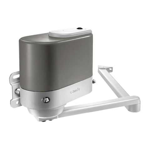
SOMFY
SOMFY AXOVIA MULTIPRO installation instructions
Viking
Viking X-9S Installation instructions and safety information
Chamberlain
Chamberlain SLY300E Mechanical installation
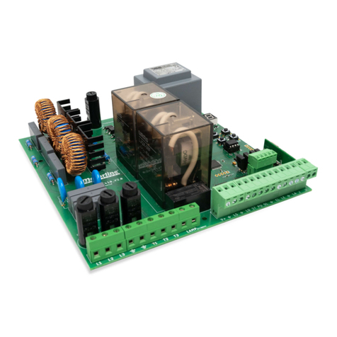
Motorline
Motorline MC410 installer and user manual
