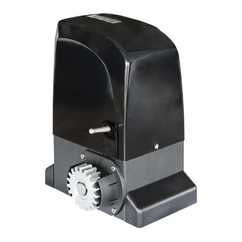
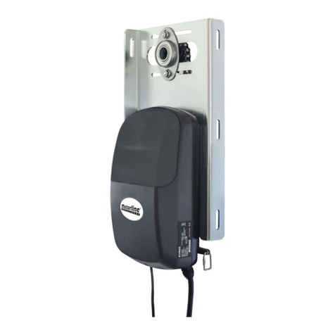
Motorline MC410 Operation and installation manual

F1
F2
F3
L1 L2 V+
L3 T1 LAMPT2 T3 LS LO OL CL LE LAST PU
LS LO ST PU OL LS LE LA
R G B Y V+
v1.2
REV. 03/2021
MC410MC410 EN
INSTALLER AND USER’S MANUAL

1A 1B
1B
4A
4A
4B
5A
6A
7A
7B
8B
8A
10A
8B
10B
9A
11A
11B
12A
12B
13A
14A
13B
ENEN
00. CONTENT
INDEX
TECHNICAL SPECIFICATIONS
LEDs
CONNECTORS
. SAFETY INSTRUCTIONS
INSTALLATION MAP (STARK)
INSTALLATION MAP (KVM105-KVM110-KVM115)
BASE INSTALLATION PROCESS
. INSTALLATION
. THE CONTROL BOARD
PROGRAMMING AND DELETE TRANSMITTERS
. PROGRAMMING
MENUS P
P1 - P2 - P3 - P4
P0 | AUTOMATIC PROGRAMMING
P7 - P8 - P9
MENUS E
P5 - P6
P0 | SEMI-AUTOMATIC PROGRAMMING
E0 - E1 - E2
E3 - E5 - E6 - E7
E8 - E9
DISPLAY INDICATIONS
. FUNCTIONS
FINAL CONSUMERS INSTRUCTIONS AND SPECIALIZED INSTALLERS
ERL ERRORS
. TROUBLESHOOTING
. COMPONENTS TEST
ATTENTION:
01. SAFETY INSTRUCTIONS
This product is certified in accordance with European
Community (EC) safety standards.
This product complies with Directive 2011/65/EU of the
European Parliament and of the Council, of 8 June 2011, on
the restriction of the use of certain hazardous substances
in electrical and electronic equipment and with Delegated
Directive (EU) 2015/863 from Commission.
(Applicable in countries with recycling systems).
This marking on the product or literature indicates that the
product and electronic accessories (eg. Charger, USB cable,
electronic material, controls, etc.) should not be disposed
of as other household waste at the end of its useful life. To
avoid possible harm to the environment or human health
resulting from the uncontrolled disposal of waste, separate
these items from other types of waste and recycle them
responsibly to promote the sustainable reuse of material
resources. Home users should contact the dealer where
they purchased this product or the National Environment
Agency for details on where and how they can take these
items for environmentally safe recycling. Business users
should contact their vendor and check the terms and
conditions of the purchase agreement. This product and
its electronic accessories should not be mixed with other
commercial waste.
This marking indicates that the product and electronic
accessories (eg. charger, USB cable, electronic material,
controls, etc.) are susceptible to electric shock by direct or
indirect contact with electricity. Be cautious when handling
theproductandobserveallsafetyproceduresinthismanual.

2A EN
GENERAL WARNINGS
•This manual contains very important safety and usage information.
very important. Read all instructions carefully before beginning the
installation/usage procedures and keep this manual in a safe place
that it can be consulted whenever necessary.
•This product is intended for use only as described in this manual. Any
other enforcement or operation that is not mentioned is expressly
prohibited, as it may damage the product and put people at risk causing
serious injuries.
•This manual is intended firstly for specialized technicians, and does not
invalidate the user’s responsibility to read the “User Norms” section in
order to ensure the correct functioning of the product.
•The installation and repair of this product may be done by qualified
and specialized technicians, to assure every procedure are carried
out in accordance with applicable rules and norms. Nonprofessional
and inexperienced users are expressly prohibited of taking any action,
unless explicitly requested by specialized technicians to do so.
•Installations must be frequently inspected for unbalance and the
wear signals of the cables, springs, hinges, wheels, supports and other
mechanical assembly parts.
•Donotuse the product ifitisnecessaryrepair or adjustmentisrequired.
•When performing maintenance, cleaning and replacement of parts, the
product must be disconnected from power supply. Also including any
operation that requires opening the product cover.
•The use,cleaning and maintenanceof this product may becarried out by
any persons aged eight years old and over and persons whose physical,
sensorial or mental capacities are lower, or by persons without any
knowledge of the product, provided that these are supervision and
instructions given by persons with experienced in terms of usage
of the product in a safe manner and who understands the risks and
dangers involved.
•Children shouldn’t play with the product or opening devices to avoid
the motorized door or gate from being triggered involuntarily.
WARNINGS FOR TECHNICIANS
•Before beginning the installation procedures, make sure that you have
all the devices and materials necessary to complete the installation of
the product.
•You should note your Protection Index (IP) and operating temperature
to ensure that is suitable for the installation site.
•Provide the manual of the product to the user and let them know how
to handle it in an emergency.
•If the automatism is installed on a gate with a pedestrian door, a door
locking mechanism must be installed while the gate is in motion.
•Do not install the product “upside down” or supported by elements do
not support its weight. If necessary, add brackets at strategic points to
ensure the safety of the automatism.
•Do not install the product in explosive site.
•Safety devices must protect the possible crushing, cutting, transport
and danger areas of the motorized door or gate.
•Verify that the elements to be automated (gates, door, windows,
blinds, etc.) are in perfect function, aligned and level. Also verify if the
necessary mechanical stops are in the appropriate places.
•The central must be installed on a safe place of any fluid (rain, moisture,
etc.), dust and pests.
•You must route the various electrical cables through protective tubes,
to protect them against mechanical exertions, essentially on the power
supply cable. Please note that all the cables must enter the central
from the bottom.
•If the automatism is to be installed at a height of more than 2,5m from
the ground or other level of access, the minimum safety and health
requirements for the use of work equipment workers at the work of
Directive 2009/104/CE of European Parliament and of the Council of 16
September 2009.
01. SAFETY INSTRUCTIONS

3A EN
•Attach the permanent label for the manual release as close as possible
to the release mechanism.
•Disconnect means, such as a switch or circuit breaker on the electrical
panel, must be provided on the product’s fixed power supply leads in
accordance with the installation rules.
•If the product to be installed requires power supply of 230Vac or
110Vac, ensure that connection is to an electrical panel with ground
connection.
•The product is only powered by low voltage satefy with central (only
at 24V motors)
WARNINGS FOR USERS
•Keep this manual in a safe place to be consulted whenever necessary.
•If the product has contact with fluids without being prepared, it must
immediately disconnect from the power supply to avoid short circuits,
and consult a specialized technician.
•Ensure that technician has provided you the product manual and
informed you how to handle the product in an emergency.
•Ifthesystemrequiresanyrepairormodification,unlocktheautomatism,
turn off the power and do not use it until all safety conditions have
been met.
•In the event of tripping of circuits breakers of fuse failure, locate
the malfunction and solve it before resetting the circuit breaker or
replacing the fuse. If the malfunction is not repairable by consult this
manual, contact a technician.
•Keep the operation area of the motorized gate free while the gate in in
motion, and do not create strength to the gate movement.
•Do not perform any operation on mechanical elements or hinges if the
product is in motion.
RESPONSABILITY
•Supplier disclaims any liability if:
•Product failure or deformation result from improper installation
use or maintenance!
•Safety norms are not followed in the installation, use and
maintenance of the product.
•Instructions in this manual are not followed.
•Damaged is caused by unauthorized modifications
•In these cases, the warranty is voided.
01. SAFETY INSTRUCTIONS
SYMBOLS LEGEND:
• Important safety
notices
• Useful information
• Programming
information
• Potentiometer
information
• Connectors
information
• Buttons
information

4A 4B
F1
F2
F3
L1 L2 V+
L3 T1 LAMPT2 T3 LS LO OL CL LE LAST PU
LS LO ST PU OL LS LE LA
R G B Y V+
ENEN
• Power Supply 400V 3~ ±10% (50Hz-60hz)
• Flashing light’s output (NO) 230Vac (1000W máx)
• RGB Lightbulb’s output 24Vdc (100mA máx)
• Motor’s output 400Vac (1500W máx)
• Auxiliary accessories output 24Vdc (325mA máx)
• Working temperature -25°C a +55°C
• Incorporated Radio Receptor 433,92 Mhz
• OP Transmitters 12bits or Rolling Code
• Maximum Memory Capacity 100 (full opening)
100 (pedestrian opening)
• Control board Dimensions 172 x 184 mm
• Fuse F1-F2-F3 T 8A 250V
• Fuse F4 T 63ma 250V retardo
. CONTROL BOARD
TECHNICAL SPECIFICATIONS
The MC is a three-phase electronic control board (V phases) with a soft start and
stop system, developed mainly to equip the engines STARK (sliding gates) and KVM
(sectional gates) of the Motorline brand.
The soft start and stop functions enable more precise operation, thus saving all mechanical
components of the gate and operator, as well as protection against exponential current
increase when starting AC motors.
Soft stopping also reduces the likelihood that the doors will be blocked when closing, as well
as reducing noise when closing the door.
. CONTROL BOARD
CONNECTORS
CN1
01 (L1) • Input Phase 1 - 400V
02 (L2) • Input Phase 2 - 400V
03 (L3) • Input Phase 3 - 400V
Power Supply 400Vac
04 (Ground) • Grounding connection
05 (Ground) • Grounding connection Motor and power ground connection
06 (T1) • Motor Output Phase 1 - 1500W máx.
07 (T2) • Motor Output Phase 2 - 1500W máx.
08 (T3) • Motor Output Phase 3 - 1500W máx.
Power Supply 110/230Vac
09 (LAMP1) • Flashing light Output - 1000W
10 (LAMP2) • Flashing light Output - 1000W
Courtesy light or Flashing light: This output
allows the connection of a courtesy light or a
Flashing light.
CN2
11 (V+) • Power supply 24Vdc 325mA max.
12 (GND) • Power supply 24Vdc 325mA max. 24Vdc Auxiliary Power Supply
13 (LS) • Full Pulsing Input (NA)
14 (GND) • Common
15 (LO) • Pedestrian Pulsing Input (NA)
Pushbuttons: This circuit allows the connection
of pushbuttons for full or pedestrian opening
16 (ST) • Button STOP Input (NC)
17 (PU) • Sequential Pushbutton (NA)
ST: This circuit allows the connection of a button
stop. Its operation depending on the
P6 configuration (check page 9A).
18 (OL) • Opening limit-switch (NC)
19 (GND) • Common
20 (CL) • Closing limit-switch (NC)
Limit switches: 03 and 04: The control unit requires
the connection of limit switches when opening
and closing (both in NC). The activation of any of
the limit switches causes the movement to stop
immediately. The activation of the limit switches is
visible on the display by OP (opening limit switch
activated) and CL (closing limit switch activated),
as well as on the OL and CL leds.
21 (LE) • Photocells 1 (NC)
22 (GND) • Common
23 (CL) • Photocells 2 (NC)
Safety circuits: This circuit allows the connection
of photocells. Its operation depending
on the configuration of the P5 and P6 menus
(check page 9A).
24 (GND) • Common
25 (ANT) • Antenna
LEDs
LEDs
+24V • LED On indicates that the line for V+ output is OK.
+5V • LED On indicates that the line for 5V is OK.
LS • LED On when the Pedestrian Pushbutton is pressed.
LO • LED On when the Total Pushbutton is pressed.
ST • LED On when the ST circuit is closed.
PU • LED On when the Sequential Pushbutton is pressed.
OL • LED On indicates limit switch opening in closed state. That is, it is not within limits.
CL • LED On indicates limit switch Closing in closed state. In other words, it is not within the
limits.
LE • LED On when the
↓ LE
circuit
is closed.
LA • LED On when the
↓ LA circuit is closed.

5A
V+
LAMP LS LO OL CL LE LAST PU
LS LO ST PU OL LS LE LA
+
1 2
-
+
1 2
-
+
1 2
-
COM
3 4
NC
NO
+
1 2
-
COM
3 4
NC
NO
F1
F2
F3
LS LO ST PU OL LS LE LA
L1 L2 L3 T1 LAMPT2 T3 V+ LS OL CL LE LASTLO PU
R G B Y V+
~ ~
TX RX
TX RX
R G B Y V+
F2
F3
L1 L2 L3 T1 LAMPT2 T3
V+ LS LO OL CLST PU
~ ~
~ ~
EN
. INSTALLATION
INSTALLATION MAP (STARK)
Pedestrian
or Close
Pushbutton
Motor connection
Total or Open
Pushbutton
Step by step
Pushbutton
Flashlight
(Example)
Circuit
Circuit
Limit switch
Antenna
Ground
Ground
Power Supply
(- Phase cable)
OPEN
CLOSE
STOP
Button
FLASHLIGHT RGB
STARK
SCMV OPTIONAL

6A
F1
F2
F3
LS LO ST PU OL LS LE LA
L1 L2 L3 T1 LAMPT2 T3 V+ LS LO OL CL LE LAST PU
R G B Y V+
F2
F3
L1 L2 L3 T1 LAMPT2 T3
V+ LS LO OL CLST PU
AB COM FE FO FC S1 S1
(1) (2) (3) (4) (5) (6) (7) (8)
(1) (2) (3) (4) (5) (6) (7) (8)
+
1 2
-+
1 2
-COM
3 4
NC
NO
TX RX
910
10
9
~
~
~
~
1 2 3 11 4 65
11
8
7
1 2 3 5 6 4 7 8
EN
. INSTALLATION
INSTALLATION MAP (KVM-KVM-KVM)
Connections
(Motor)
Pushbutton
Flashlight
(Example)
Control Board
Loading dock
Antenna
Ground (Green/Yellow)
Power Supply
(- Phase cable)
Photocells
SCMV OPTIONAL
Control
Board Inside
Black
Blue
Brown
White
Green
Grey
Orange
Red
-wire cable
Black
Blue
Brown
Red
Green
White
Orange
Grey

7A 7B
ENEN
01 • Make connections for all accessories according to the wiring diagram (page 5A).
02 • Connect the control board to a 400V 3 ~ phase power supply (terminals L1, L2, L3)
03 • Check that the movement of the gate matches the one shown on the display:
. INSTALLATION
BASE INSTALLATION PROCESS
. PROGRAMMING
PROGRAMMING AND DELETE TRANSMITTERS
O processo de instalação, assume que o portão já tem as chapas de fim de curso instaladas.
Para mais informações consulte o manual do motor.
02 • Select [SU]
use
UP or DW
.
05 • Press cmd for 3 sec
and the location will be
empty.
The display will blink
and the position will
be free.
02 • The display will show [SU].
03 • [SU] will flash.
04 • [LU] flashes, confirming that all
commands have been deleted.
01 • Press the cmd button for 10 sec.
01 • Press the
cmd button for
3 sec.
TRANSMITTER PROGRAMMING FOR TOTAL OPENING
TRANSMITTER PROGRAMMING FOR PEDESTRIAN OPENING.
02 • Select [SU]
use
UP or DW
.
03 • Press cmd
once to confirm. 04 • Use
UP or DW
to select the
transmitter
location you want
to delete.
04 • The first free
position appears.
05 • Press the command
button you want to
program. The display will
blink and move to the
next free location.
03 • Press cmd
once to confirm.
01 • Press the
cmd button for
3 sec.
• PROGRAMMING TRANSMITTERS
• ERASE ALL THE TRANSMITTERS
• ERASE TRANSMITTERS
• If you do not press any key for 10 sec.
the control board will return to standby.
CLOSING OPENING
In case the display does not match the movement
of the gate, disconnect the control panel from
the power supply and change the wires T1 and T2
and check if it is correct with OP and CL.
04 • Check the limit switches so that the CL LED goes out when the closing limit switch is
activated and the OP LED goes out when the opening limit switch is activated.
05 • Make an automatic or semi-automatic programming of the course - menu [P0] (page 9A).
06 • If necessary, adjust the gate slowing time at the opening and in the closing - menu [P1]
(page 10A).
07 • Adjust the force - menu [P2] (page 10A).
08 • Enable or disable the use of photocells in the [P5] menu (page 10B).
09 • Enable or disable the use of photocells 2 in the [P6] menu (page 10B)
10 • Program a command (page 7B).
The control board is now fully configured!
Check the pages of the menu programming if you want to configure other features of the
Control board.

8A 8B
ENEN
• We can only enter programming with the gate stopped (electrically).
• To access the P MENU press the MENU for sec.
• To access the E MENU press the MENU for sec.
• Use UP or DW to navigate through the menus
• Press MENU when you want to confirm access to a menu.
• Press UP or DW simultaneously to exit programming
MENUS P
. FUNCTIONS . FUNCTIONS
MENUS E
MENU FUNCTION MÁX. MIN.
PROGRAMÁVEIS STATE FACTORY
VALUE OL FACTORY
VALUE SE
Programação do curso -Prog. automatic
Prog. semi automatic --
Deceleration time adjustment Slowing down at opening
Slowing down on closing
Force adjustment Force adjustment 06
Pedestrian Course time Time adjustment in pedestrian
course
Pause time
Adjusting the pause time
total opening
Adjusting the pause time
pedestrian opening
Photocell Circuit
(activation and management of
the operating mode)
Disables
Ative
In Opening
In Closing
Invert
Stop
Invert 2 sec. and Stop
Photocell Circuit
(activation and management of
the operating mode)
Disables
Ative
In Opening
n Closing
Invert
Stop
Invert 2 sec. and Stop
Disables the ST
emergency button
Activates the ST
emergency button
Operating logic
Automatic mode function
01
Step by step mode function
Condominium mode function
Flashing light
Flashing (opening and
closing)
00
Step by step mode function
Courtesy light
Remote programming Distance PGM OFF 9B
Distance PGM ON
0 1
min. max.
0 2
min. max.
0 2
min. max.
0 2
min. max.
0 1
min. máx.
0 1
min. max.
0 1
min. máx.
0 2
min. max.
0 1
min. max.
0 1
min. max.
99s
0s
min. max.
99s
0s
min. max.
45s
0s
min. max.
0 9
min. max.
MENU FUNCTION MAX. MIN.
PROGRAMMABLE STATE FACTORY
VALUE
OL
FACTORY
VALUE SE
Present Man
Deactivates present man
Activates present man
Activates present man - Close 00
Disables push buttons mode
Activates push buttons mode
Soft start Desactivates Soft start 03
Activates Soft start
Courtesy light time Courtesy light time adjustment (min) 03
Follow me -
Desactivates follow me 00
Activates follow me (Open gate)
Electronic brake Adjusting the electric brake power 00
Deceleration Speed Deceleration Speed adjustment 06
Manuevers counter -Shows the number of maneuvers --
Reset - Select version Reset - Sliding Motor 00
Reset - Sectional Motor
RGB Output -
Continued output 01
Intermittent output
TRANSMITTER
Transmitter programming for total opening. B
Transmitter programming for pedestrian opening. B
0 1
min. max.
0 4
min. max.
0 9
min. max.
0 9
min. max.
99m
0m
min. max.
0 2
min. max.

9A 9B
ENEN
. FUNCTIONS
P | SEMI-AUTOMATIC PROGRAMMINGP | AUTOMATIC PROGRAMMING
. FUNCTIONS
This menu allows automatic programming of the engine and slowdown.
Note • This mode requires the use of limit switches.
During automatic programming, the engine performs the following maneuvers:
1 • Slowly close the gate until it reaches the closing limit switch
2 • Opens slowly for approximately 10 seconds
3 • Close slowly until closing limit switch is reached
4 • Opens gate at normal speed until reaching the opening limit switch
5 • Close the gate at normal speed until it reaches the closing limit switch
Steps 2 and 3 are only performed if [P2-Fd] is set to a value equal to or greater than 1.
If [P2-Fd] is set to 0 (zero), you will only do steps 1, 4 and 5.
03 • Appears
[AU]. Press MENU
for 1 second to
start automatic
programming.
01 • Press MENU for 3
seconds. 02 • Appears [P0].
Press MENU for 1
second.
04 • When
programming is
complete, the display
returns to the initial
state [--].
This menu allows you to program the engine's working time in a semi-automatic way, allowing you to
manually define the moment when the slowdowns start.
In this way, we automatically set the value of Menu [P1] as well as reducing the inertia of the door
when it reaches the limit switches in programming.
If you do not press MENU at any time, a
automatic programming without Relanty during the course.
03 • Appears [AU].
Press UP 1 time to
show MA.
01 • Press MENU for 3
seconds. 02 • Appears [P0].
Press MENU for 1
second.
04 • When [MA]
appears, press MENU
for 1 second.
The engine will initiate
a slow door close.
05 • When the closing limit switch is
reached or pressing the remote, it will
open automatically.
06 • Press MENU or another controller
as the command, when you want to
start the slowdown at the opening.
07 • When the closing limit switch is
reached or pressing the remote, it will
close automatically.
08 • Press MENU or another controller
as the command, when you want to
start the slowdown at the closing.

10A 10B
ENEN
P - P
. FUNCTIONS
P1 - P - P - P
. FUNCTIONS
TIME ADJUSTMENT
This menu allows you to define the slowdown time for each sheet when
opening and closing.
Note • Whenever there is a reversal of the direction of travel, the preset
deceleration time is increased by 2 sec. up to a maximum of 25 sec.
DEFAULT
VALUE MIN
VALUE MAX
VALUE
03 00 45
01 • Press MENU until it appears [dA].
02 • Use UP or DW to navigate the parameters [dA] and [dF].
03 • Press MENU to edit the value.
04 • Use UP and DW to change the value.
05 • Press MENU for 2sec. to save the new value.
FORCE ADJUSTMENT
This menu allows you to define the force that is injected into the engine when
it moves at normal speed.
DEFAULT
VALUE MIN
VALUE MAX
VALUE
06 00 09
01 • Press MENU until it appears [F0].
02 • Press MENU to edit the value.
03 • Use UP and DW to change the value.
04 • Press MENU for 2sec. to save the new value.
PEDESTRIAN COURSE TIME
This menu allows you to set the pedestrian travel time. DEFAULT
VALUE MIN
VALUE MAX
VALUE
10 00 99
01 • Press MENU to edit the value.
02 • Use UP and DW to change the value.
03 • Press MENU for 2sec. to save the new value.
PAUSE TIME
Allows to set the pause time at total opening.
Allows to set the pause time at the pedestrian opening.
DEFAULT
VALUE MIN
VALUE MAX
VALUE
10 00 99
01 • Press MENU until it appears [AF].
02 • Use UP or DW to navigate the parameters.
03 • Press MENU to edit the value.
04 • Use UP and DW to change the value.
05 • Press MENU for 2sec. to save the new value.
PHOTOCELLS 1 PROGRAMMING
This menu allows you to program the LE safety behavior (photocell 1).
Enable or disable photocells
Define whether this security will act when opening or closing the gate.
(00 - acts on closing / 01 - acts on opening)
Define the behavior that the gate will have when this security is activated.
When safety is activated, the direction of movement of the gate is
reversed
When the security is activated, the movement of the gate stops.
When security is activated, the movement of the gate reverses for 2 sec.
is for. The movement is not resumed automatically.
LE
DEFAULT
VALUE
LE
OFF LE
ON
00 00 01
HC
DEFAULT
VALUE
HC
CLOSE HC
OPEN
00 00 01
HL
DEFAULT
VALUE
FUNCTIONS
HL
00 00 | 01 | 02
01 • Press MENU until it appears [LE].
02 • Use UP or DW to navigate the parameters.
03 • Press MENU to edit the value.
04 • Use UP and DW to change the value.
05 • Press MENU for 2sec. to save the new value.
PHOTOCELLS 2 PROGRAMMING
This menu allows you to program the LA safety behavior (photocell 2).
Enable or disable photocells 2.
Define whether this security will act when opening or closing the gate.
(00 - acts on closing / 01 - acts on opening)
Define the behavior that the gate will have when this security is activated.
When safety is activated, the direction of movement of the gate is
reversed
When the security is activated, the movement of the gate stops.
When security is activated, the movement of the gate reverses for 2 sec.
is for. The movement is not resumed automatically.
Enable or disable the Stop push button function
LA
DEFAULT
VALUE
LA
OFF LA
ON
00 00 01
HC
DEFAULT
VALUE
HC
OFF HC
ON
01 00 01
HL
DEFAULT
VALUE
FUNCTIONS
HL
02 00 | 01 | 02
HE
DEFAULT
VALUE
HE
OFF HE
ON
00 00 01
01 • Press MENU until it appears [LA].
02 • Use UP or DW to navigate the parameters.
03 • Press MENU to edit the value.
04 • Use UP and DW to change the value.
05 • Press MENU for 2sec. to save the new value.

11A 11B
ENEN
E - E1 - E2
. FUNCTIONS
P- P - P
. FUNCTIONS
OPERATING LOGIC
This menu allows to set the operating logic of the automation
Automatic Mode - Whenever there is an order, the movement is reversed.
Step-by-step mode - Logic opens / stops / closes / stops.
Note • Stopping movement during closing disables automatic closing.
Condominium mode - Does not respond to orders during opening and
pause time.
DEFAULT
VALUE
AUTOMATIC
STEP BY STEP
CONDOMINIUM
00 00 01 02
01 • Press MENU to edit the value.
02 • Use UP and DW to change the value.
03 • Press MENU for 2sec. to save the new value.
REMOTE PROGRAMMING
This menu allows you to enable/disable remote programming. DEFAULT
VALUE
PGM Á
DISTÂNCIA
OFF
PGM Á
DISTÂNCIA
ON
00 00 01
01 • Press MENU to edit the value.
02 • Use UP and DW to change the value.
03 • Press MENU for 2sec. to save the new value.
FLASHING LIGHT
This menu allows you to define the mode of operation of the firefly (LAMP).
The default value is 0 (flashing).
Flashing (opening and closing) - In the 2-second intermittent opening, in the
1-second intermittent closing. At pause time it remains on.
Step by step mode - In the opening and closing movement, the firefly is
permanently on. When stopped it remains off.
In the opening and closing movement the firefly is permanently on. When in
pause time it remains on.
When stopped or closed, the time defined in E2 remains on.
DEFAULT
VALUE
FLASHING
STEP BY STEP
FLASHING/STOP
00 00 01 02
01 • Press MENU to edit the value.
02 • Use UP and DW to change the value.
03 • Press MENU for 2sec. to save the new value.
Remote Programming Operation (PGM ON):
• Press the keys indicated in the image simultaneously for 10 seconds
and the flashing light will flash (the 1st free position appears in the display).
Each time you store 1 command, the control board will exit remote
programming. If you want to memorize more commands, you will
always have to repeat the process of pressing the command keys
simultaneously for 10 seconds for each new command.
PRESENT MAN
Enable or disable man present.
Present inactive man mode
Present man active - It is necessary to be constantly pressing the entrance
panel to open and close the door.
Present man active on closing - It is necessary to be constantly pressing
the entrance panel to close the door. The opening operation is performed
automatically with just a click on the entrance panel.
Note • With the present man active, the RF commands do not work
DEFAULT
VALUE VMIN
VALUE MAX
VALUE
00 00 02
Activate the operation in entrance panel mode, LS (Full opening), LO (Full
closing).
The default value is 0 (disabled), LS (Full aperture) LO (Pedestrian aperture).
DEFAULT
VALUE OFF ON
00 00 00
01 • Press MENU until it appears [HP] .
02 • Use UP or DW to navigate the parameters.
03 • Press MENU to edit the value.
04 • Use UP and DW to change the value.
05 • Press MENU for 2sec. to save the new value.
SOFT START
This menu allows you to activate the soft start.
The higher the selected value, the longer the soft start duration.
The maximum value is 4.
DEFAULT
VALUE MIN
VALUE MAX
VALUE
03 00 04
01 • Press MENU to edit the value.
02 • Use UP and DW to change the value.
03 • Press MENU for 2sec. to save the new value.
COURTESY LIGHT TIME
This menu allows you to adjust the courtesy light time for the closed, open and
stopped gate.
The maximum time is 99 minutes.
Note • This parameter is only activated if option 2 is selected in P8.
DEFAULT
VALUE MIN
VALUE MAX
VALUE
03 00 99
01 • Press MENU to edit the value.
02 • Use UP and DW to change the value.
03 • Press MENU for 2sec. to save the new value.

12A 12B
ENEN
E - E
. FUNCTIONS
E - E - E - E
. FUNCTIONS
FOLLOW ME
Disabled
The control board, when in the open position, gives a closing order of 5 sec. after
the safety device detects the passage of an object / user
The control panel, when in the open or in the open position, gives a closing order
of 5 sec. after the safety device detects the passage of an object / user.
DEFAULT
VALUE MIN
VALUE MAX
VALUE
00 00 02
01 • Press MENU to edit the value.
02 • Use UP and DW to change the value.
03 • Press MENU for 2sec. to save the new value.
BRAKE/LOCK/PUSH
Activate the electronic brake.
This menu can be programmed between the values 0 and 9, where 0 means
the softstart is off and 9 means more brake time.
Note • The higher the set value, the greater the engine heating.
DEFAULT
VALUE MIN
VALUE MAX
VALUE
00 00 09
01 • Press MENU until it appears [00].
02 • Use UP or DW to navigate the parameters.
03 • Press MENU to edit the value.
04 • Use UP and DW to change the value.
05 • Press MENU for 2sec. to save the new value.
DECELERATION SPEED
This menu allows you to adjust the deceleration speed.
DEFAULT
VALUE MIN
VALUE MAX
VALUE
06 00 09
01 • Press MENU to edit the value.
02 • Use UP and DW to change the value.
03 • Press MENU for 2sec. to save the new value.
MANUEVERS COUNTER
This menu allows you to view the number of maneuvers performed.
01 • Press MENU to view.
RESET – SELECT VERSION
This menu allows you to reset the factory values for the two existing
versions:
Reset Sectional Doors to factory settings
Reset Sliding Gates to factory settings
DEFAULT VALUE RESET
(SECTIONAL) RESET
(SLIDING)
00 01 02
01 • Press MENU to edit the value.
02 • Use UP and DW to change the value to [01] or [02].
03 • Press MENU for 2sec. to save the new value.
RGB OUTPUT
This menu allows you to set the operation mode of RGB outputs.
DEFAULT
VALUE CONTINUOUS
OUTPUT INTERMITTENT
OUTPUT
01 00 01
01 • Press MENU to edit the value.
02 • Use UP and DW to change the value.
03 • Press MENU for 2sec. to save the new value.

13A 13B
ENEN
ERL ERRORS
. COMPONENTS TEST
If the display shows the error ERL, , it means that one of the input phases is missing or
that the motor connections are incorrect.
Check all connections and try again.
To remove errors from the display you just need to click on any button on the control panel
or in charge.
NOTES:
• This control board was developed only to work with Motorline motors, however if you
want to work with motors from other manufacturers make sure that this motor is in star
configuration and that it is a 400V motor that does not exceed 1500W.
INDICAÇÕES DO DISPLAY
. FUNCTIONS
IN STOP POSITION, FULLY OPEN
IN STOP POSITION, MIDDLE POSITION
IN STOP POSITION, FULLY CLOSED
TOTAL OPENING BUTTON PRESSED
PEDESTRIAN OPENING BUTTON PRESSED
CONTROL BOARD RUNNING OPENING COURSE
CONTROL BOARD RUNNING CLOSING COURSE
END OF OPENING COURSE TIME
END OF CLOSING COURSE TIME
ALL TRASMITTERS DELETED
TRANSMITTER ADDED IN THE INDICATED POSITION
OBSTRUCTED PHOTOCELL
OBSTRUCTED PHOTOCELL 2
IN PAUSE TIME
IN PEDESTRIAN PAUSE TIME
EMERGENCY BUTTON PRESSED
NO LIMIT-SWITCHES INSTALL
PHASE 1 OR MOTOR FAILURE
PHASE 2 OR MOTOR FAILURE
PHASE 3 OR MOTOR FAILURE

14A EN
. TROUBLESHOOTING
FINAL CONSUMERS INSTRUCTIONS AND SPECIALIZED INSTALLERS
Anomaly Procedure Behavior Procedure II Discovering the origin of the problem
• Motor
doesn’t
work.
• Make sure you
have power supply
connected to control
board and if it is
working properly.
• Still not working. • Consult a qualified
MOTORLINE technician.
• Motor
doesn’t
move but
makes
noise.
• Unlock motor
and move the gate
by hand to check
for mechanical
problems on the
movement.
• Is the gate stuck? • Consult a qualified gates
technician.
1 • Check all motion axis and associated motion systems related with the gate and automatisme (rails, pulleys, bolts, hinges, etc) to find out what is
the problem.
• The gate moves
easily?
• Consult a qualified
MOTORLINE technician.
• Motors
open but
doesn’t
close.
• Unlock motor(s)
and move the roller
by hand to closed
position. Block
the motor again
and turn off power
supply for 5 seconds.
Reconnect it and
send order to open
gate using remote
control.
• Gate opened but
didn’t close again.
1 • Check if there is any
obstacle in front of the
photocells;
2 • Check if any of the
control devices (Key
Selector, Pushbutton, Video
Intercom, etc.) are stucked
and sending permanent
signal to control board;
3 • Consult a qualified
MOTORLINE technician.
• Motor
doesn’t
make
complete
course.
• Unlock motor
and move gate
by hand to check
for mechanical
problems on the
gate.
• Encountered
problems?
• Consult an experienced
gates expert.
1 • Check all motion axis and associated motion systems related with the gate and automatisme (rails, pulleys, bolts, hinges, etc) to find out what is
the problem.
• The gate moves
easily?
• Consult a qualified
MOTORLINE technician.
1 • Open control box and check if
it has 230V power supply;
2 • Check input fuses;
3 • Disconnect motors from
control board and test them by
connecting directly to power
supply in order to find out if they
have problems (see page 11B).
4 • If the motors work, the
problem is on the control board.
Pull it out and send it to our
MOTORLINE technical services
for diagnosis;
5 • If the motors don’t work,
remove them from installation
site and send to our MOTORLINE
technical services for diagnosis.
1 • Check capacitors, testing
operator with new capacitor;
2 • If capacitors are not the
problem, disconnect motors
from control board and it them
by connecting directly to power
supply in order to find out if it has
problems (see page 11B).
3 • f the motors work, the problem
is from control board. Pull it out
and send it to our MOTORLINE
technical services for diagnosis;
4 • If the motors don’t work,
remove them from installation
site and send to our MOTORLINE
technical services for diagnosis.
1 • Check capacitors, testing with
new capacitors;
2 • If capacitors are not the
problem, disconnect motor
from control board and test it
by connecting directly to power
supply in order to find out if it is
broken;
3 • If the motor(s) doesn’t work,
remove it from installation site
and send to our MOTORLINE
technical services for diagnosis.
4 • If motor work well and move
gate at full force during the entire
course, the problem is from
controller. Set force using trimmer
on the board. Make a new working
time programming, giving suffient
time for opening and closing with
appropriate force (consult control
board manual).
5 • If this doesn’t work, remove
control board and send it to
MOTORLINE technical services.
NOTE:
Setting force of the controller
should be suficiente to make
the gate open and close without
stopping, but should stop and
invert with a little effort from a
person. In case of safety systems
failure, the gate shall never cause
physical damaged to obstacles
(vehicles, people, etc.).
All control boards MOTORLINE have LEDs that
easily allow to conclude which devices are
with anomalies. All safety devices LEDs (Le)
in normal situations remain On. All "START"
circuits LEDs in normal situations remain Off.
If LEDs devices are not all On, there is some
security systems malfunction (photocells,
safety edges). If "START" circuits LEDs are turn
(Op and Cl), there is a control device sending
permanent signal.
A) SECURITY SYSTEMS:
1 •Close with a shunt all safety systems
on the control board (check manual of the
control board in question). If the automated
system starts working normally check for
the problematic device.
2 • Remove one shunt at a time until you find
the malfunction device.
3 • Replace it for a functional device and
check if the motor works correctly with all
the other devices. If you find another one
defective, follow the same steps until you find
all the problems.
B) START SYSTEMS:
1 • Disconnect all wires connected to the
START connector.
2 • If the LED turned OFF, try reconnecting one
device at a time until you find the defective
device.
NOTE:
In case procedures described in sections A)
and B) don’t result, remove control board and
send to our MOTORLINE technical services for
diagnosis.
Table of contents
Other Motorline Gate Opener manuals