TOP CAT 36G-2 Instructions for use

General Operators Instructions
and
Maintenance Manual
36G Series
Die Grinders
Top Cat ® Air Tools, Manufactured by T.C. Service Co.
38285 Pelton Road, Willoughby, OH 44094 U.S.A.
Ph: (440) 954-7500 or (800) 321-6876 ● Fax: (440) 954-7118 or (877) 800-3589
E-Mail: [email protected] ● Web Site: www.tcservice.com
Read Safety Recommendations Before Operating Tool
Model
Number
Exhaust
Direction
Throttle
Type
Rated
Speed
Power
Output
Case
Material
Weight Overall
Length Diameter Working Air
Consumption
Collet
Size
Aluminum Steel
36G-2 (F) Front
or
Side
(L) Lever
or
(K) Safety
Lever
30000
R.P.M.
0.6 H.P.
(450 W)
Steel
or
Aluminum
0.8 lb.
(0.4 Kg.)
1.0 lb.
(0.5 Kg).
5.2 Inches
(133 mm) 1.3 Inches
(33 mm)
20 cfm
(9.4 L/S)
1/4”
36G-4 5.3 Inches
(135 mm)
1/8”, 3/16”,
1/4”, 3 mm,
or 6 mm
*The use of type 1 or 27 wheels is not within the design of this pneumatic tool.
36GL
36G Series Die Grinders
Capacity*
● Burrs and Mounted Stones

This is meant to highlight sections of safety standards published by the American National Standards
Institute and the Occupational Safety and Health Administration. This is not meant to replace those
standards but only highlight certain areas.
When care is taken to ensure that the right tool is operated properly, and safety and maintenance
procedures are followed, accidents can be avoided. Read and follow all instructions and directions.
Comply with all rules governing the use of power tools, personal protective equipment and equipment
guards.
Remember - machines, attachments and accessories must be used only for the purpose for which
they were designed. Safety reasons and product liability prohibit any modifications to tools. Any
attachments or accessories must be agreed to in advance with an authorized technical representative
of T.C. Service Co.
The grinding equipment must be approved
for the rated speed of the machine. The rated
speed, marked on the machine, should not be
exceeded. Be sure to learn the proper handling
and storage of abrasive wheels and inserted
tooling.
Inspect the wheel guard for any signs of wear
and that it is properly mounted to the tool. Any
guard showing signs of wear such as bends,
chips, nicks, or cracks should be replaced.
Always wear eye and hearing protection, and when
necessary, other personal protective equipment
such as gloves, an apron, and helmet. Properly
fitted protective clothing cushions the operator from
vibration exposure and help prevent minor scrapes
that might occur as a result of guiding the tool along
the work piece.
Additional information on eye protection is available
in the following national regulatory standards.
1) Federal OSHA Regulations 29 CFR, Section
1910.133 (Eye and Face Protection)
2) ANSI Z87.1 (Occupational and Educational Eye
and Face Protection)
Check hose size and air pressure. The air pressure at the tool shall not
exceed 90 psi (6.2 bar). All hoses should be inspected regularly and kept
away from heat, oil and sharp edges. Be sure the tool is secured to the air
hose.
Measure the speed of grinders every 20 hours of actual use or once per
week, whichever comes first.
Tachometers must be checked and calibrated on a regular basis according
to the manufacturers recommendations
Measure speed of all types of grinders after maintenance or repair,
whenever a grinder is issued from the tool crib and at each wheel change.
Several readings should be taken.
This form of inspection should be made with the grinding wheel or tooling
removed.
Operators Instructions and Safety Precautions

Proper mounting of grinding wheels
and inserted tooling is crucial to
safe operation and efficient working
conditions. Ensure the exhaust air is
directed away from bystanders.
Disconnect the tool from
the air supply before doing
any service. This prevents
accidental start-ups.
The safety procedures for operating air tools are everyone’s responsibility. The following lists several
aspects of air tool safety that should be considered during operation. Please be aware of the these
aspects and report any unsafe practice you see to a supervisor or safety officer immediately.
1) Start any new inserted tooling or wheel under a bench and away from bystanders. (Run for a
minimum of one minute.)
2) When starting a cold/new mounted stone, apply to the work slowly, allowing the mounted stone to
warm gradually.
3) Support the work piece properly.
4) When grinding, support the work piece so that a jamming of the mounted stone or burr does not
occur. (A slot shall remain constant or become wider during operation.)
5) If a jamming of the inserted tooling does occur during a grinding operation, shut the air supply off to
the tool and ease the mounted stone or burr free. (Inspect the mounted stone or burr for damage before
continuing operation.)
6) Ensure that sparks from the process do not create a hazard to the eyes or will ignite the environment.
7) Grinders shall not be used in potentially explosive atmospheres.
8) Pneumatically driven tools are not generally insulated from coming in contact with electrical sources.
Be sure to avoid contact with wires or other possible current carrying sources.
9) The operator must check that no bystanders are in the vicinity.
10) Remember that there is a running on after the throttle has been released.
11) If a grinder fitted with a mounted stone or burr is dropped, the mounted stone or burr must be
thoroughly examined before re-use.
12) Disconnect the tool from the air source before servicing and changing mounted stones/burrs.
13) Release the control device in case of interruption of air supply.
14) Always keep the tool in a clean, dry place when not in use.
15) Beware of loose hair and clothing so as not to become tangled or trapped during operation.
16) Unexpected tool movement or breakage of inserted tooling may cause injury.
17) Unsuitable postures may not allow counteracting of normal or unexpected movement of a power
tool. (A working position shall be adopted which remains stable in the event of a break up of inserted
tooling.)
18) Do not hold the tool near the body when operating.
19) Keep a firm grip on the tool body during operation.
20) Immediately shut off the tool if unusual vibration or sound is detected. Remove and inspect the
inserted tooling or wheel, and check the tool speed (RPM) with an accurate tachometer. Use of over-
speeding grinder or unbalanced wheels may result in serious injury.
Airborne particulate resulting
from the grinding process can
cause hazards. Wear appropriate
protective equipment.
Safety in Operation

Maintenance

Disassemble
1. Disconnect air and remove all burrs, and accessories.
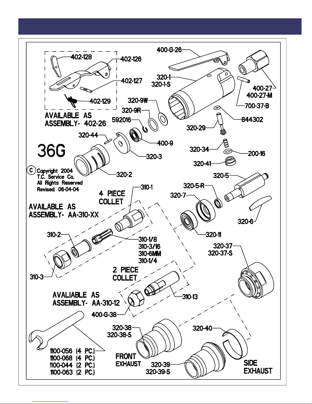
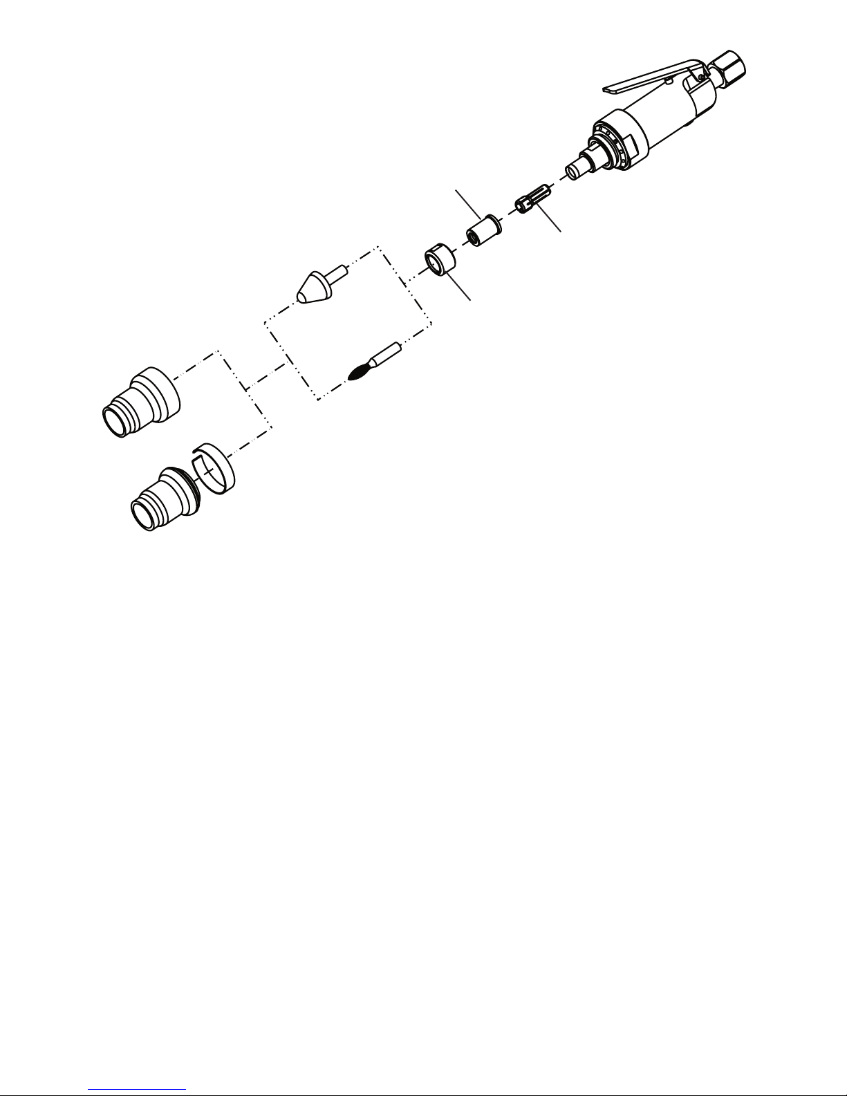
2. Remove collet nut (310-3 or 400-G-38). Remove nose piece (310-2), and insert (310-xx) if present.
3. Secure tool in vise vertically with output of tool upward. Clamp onto the flats toward the rear of the
motor housing.
4. Unscrew exhaust guard (320-38[S] or 320-39[S]), and exhaust deflector (320-40) if present.
Unscrew bearing cap (320-37[S]) from motor housing (320-1[S]) and slide motor out. Remove motor
housing from vise and take wafer (320-9W) and o-ring (320-9R) out of motor housing.
5. Slip snap ring (592016) from groove at rear of rotor (320-5).
6. Install brass jaws on vise. Secure motor assembly into vise vertically with output pointed down.
Clamp lightly the outside diameter of the cylinder (320-2) and rear endplate (320-3).
7. Use a 3/16” punch to tap spindle out of rear bearing (400-9). Be careful not to drop the front motor
assembly when it is free. Remove from vise.
8. Remove 3 blades (320-6).
9. With brass jaws still in vise, firmly clamp rotor in vise with output pointed upward. Using a wrench,
unscrew the collet body (310-1 or 310-13).
10. Support the rotor assembly vertically on a suitable drill block. Press spindle through front bearing
(320-11) with an arbor press. Remove spacer (320-5-R).
11. Remove bearing (320-11) from front endplate (320-7) with a small punch.
12. To check throttle valve unscrew throttle valve cap (320-41). Lift out valve spring (320-34) and
throttle valve (320-29). Remove and replace o-rings (844302 and 200-16) if cracked or worn.
Assembly
1. Be sure that all parts are clean and free of any abrasive.
2. Install the spacer (320-5-R) onto the threaded end of the rotor. Ensure that the spacer sits flush
against the rotor.
3. Press bearing (320-11) into recessed area of front endplate (320-7)
4. Support the front bearing assembly on a suitable drill block. Press the rotor (320-5) into the rear of
front endplate and through front bearing.
5. With brass jaws in vise, clamp firmly onto rotor (320-5) with output upward. Install the collet body
(310-1 or 310-13) onto the threaded end of the rotor and tighten with a wrench. Remove from vise.
6. Place 3 blades (320-6) into rotor slots.
7. Slip cylinder (320-2) over rotor. Be sure the alignment pin is oriented away from the front for the
motor assembly.
8. Install rear endplate (320-3) locating cylinder pin in the small hole of the rear endplate and the
cutaway on the side of the endplate over the air inlet of the cylinder.
9. Place bearing (400-9) over rear endplate. Tap in place with bearing driver (1100-802).
10. Place snap ring (592016) in spindle groove.
11. Grasp the collet body in one hand with the output downward. Place o-ring (320-9R) and then
wafer (320-9W) onto top of rear bearing. Carefully place motor housing (320-1[S]) over motor
assembly, taking care that the cover and o-ring stay in position on top of bearing. Insure that the
motor is fully into the case, then carefully turn the assembly over, so that the output points upward.
12. Secure tool in vise vertically with output of tool upward. Clamp onto the flats toward the rear of the
motor housing. Screw on the bearing cup (320-37[S]) and tighten with a wrench.
13. On 2-piece collet models, install collet nut (400-G-38). On 4-piece collet models install collet insert
(310-xx), nose piece (310-2) and collet nut (310-3).
14. On front exhaust models install exhaust guard (320-38[S]). On side exhaust models install
deflector (320-40) and exhaust guard (320-39[S]).
15. Check the operating speed with a reliable tachometer. The speed must be at or below the
stamped speed on the tool. Reinstall all safety devices and accessories.

PART DESCRIPTION
200-16 O-RING
310-3/32 3/32” DOUBLE ANGLE COLLET INSERT
209-1/8 1/8” DOUBLE ANGLE COLLET INSERT
209-3/16 3/16” DOUBLE ANGLE COLLET INSERT
209-1/4 1/4” DOUBLE ANGLE COLLET INSERT
209-3MM 3MM DOUBLE ANGLE COLLET INSERT
209-6MM 6MM DOUBLE ANGLE COLLET INSERT
310-1 4 PIECE COLLET BODY
310-2 4 PIECE COLLET NOSE PIECE
310-3 4 PIECE COLLET NUT
310-13 2 PIECE COLLET BODY
320-1 ALUMINUM CASE (SPECIFY SPEED)
320-1-S STEEL CASE (SPECIFY SPEED)
320-2 CYLINDER
320-3 REAR ENDPLATE
320-5 ROTOR
320-5-R ROTOR SPACER
320-6 BLADE (3 REQ)
320-7 FRONT ENDPLATE
320-9R O-RING
320-9W WAFER
320-11 FRONT MOTOR BEARING
320-29 THROTTLE VALVE-INCLUDES 844302
320-34 SPRING
320-37 ALUMINUM BEARING CAP
320-37-S STEEL BEARING CAP
320-38 ALUMINUM FRONT EXHAUST GUARD
320-38-S STEEL FRONT EXHAUST GUARD
320-39 ALUMINUM SIDE EXHAUST GUARD
320-39-S STEEL SIDE EXHAUST GUARD
320-40 SIDE EXHAUST DEFLECTOR
320-41 THROTTLE VALVE CAP
320-44 CYLINDER PIN
400-G-26 THROTTLE LEVER
400-G-38 COLLET NUT
400-9 REAR BEARING
400-9A SEALED REAR BEARING
400-27 1/4 NPT TO 1/4 NPT BUSHING
400-27-M 1/4 NPT TO 1/4 BSP BUSHING
402-126 SAFETY LEVER
402-127 SAFETY LEVER PIN
402-128 LOCKOUT LEVER
402-129 SAFETY LEVER SPRING
700-37B THROTTLE LEVER PIN
592016 SNAP RING
844302 O-RING
Tool Parts Listing
Note: Use of any parts other then
genuine Top Cat® parts voids any
and all warranties, and may result in
a hazardous situation and a decrease
in operating efficiency.
TOOLS
PART DESCRIPTION
1100-044 7/16” WRENCH
1100-056 9/16” WRENCH
1100-063 5/8” WRENCH
1100-068 11/16” WRENCH
1100-802 400-9 BEARING DRIVER
ACCESSORIES
PART DESCRIPTION
300-16 1/4” TO 1/8” COLLET ADAPTER
300-16-3/32 1/4” TO 3/32” COLLET ADAPTER
530216 KIT BOX
530218 KIT BOX LINER
530198 1/8” TAPER BURR
530200 1/8” FLAME BURR
530202 1/8” BALL BURR
530204 1/8” CYLINDRICAL BURR
530208 1/4” BALL BURR
530210 1/4” CYLINDRICAL BURR
530212 1/4” TREE BURR
530214 1/4” FLAME BURR
OTHER SIZES AVAILABLE
ASSEMBLIES
PART DESCRIPTION
510020 REPAIR KIT
402-26 SAFETY LEVER ASSY.
AA-530216 KIT BOX ASSY.
AA-320-1 ALUMINUM CASE ASSY.
AA-320-1-K ALUMINUM SAFETY CASE ASSY.
AA-320-1-S STEEL CASE ASSY.
AA-320-1-S-K STEEL SAFETY CASE ASSY.
SPECIFY SPEED FOR CASE ASSY.
COLLET ASSEMBLIES
PART DESCRIPTION
310-12 1/4” 2-PIECE ASSY.
AA-310-3/32 DOUBLE ANGLE 4 PIECE--3/32” INSERT
AA-310-1/8 DOUBLE ANGLE 4 PIECE--1/8” INSERT
AA-310-3/16 DOUBLE ANGLE 4 PIECE--3/16” INSERT
AA-310-1/4 DOUBLE ANGLE 4 PIECE--1/4” INSERT
AA-310-3MM DOUBLE ANGLE 4 PIECE--3MM INSERT
AA-310-6MM DOUBLE ANGLE 4 PIECE--6MM INSERT
OTHER SIZES AVAILABLE

The following suggestions will help reduce or moderate the effects
of repetitive work motion and/or extended vibration exposure:
1) Do not over-grip the machine/tool. Use only the force required to
maintain control.
2) Keep hands and body dry and warm. (Blood flow is important -
exercise hands and arms as often as necessary.)
3) Keep wrists as straight as possible. (Avoid hand positions that
require the wrist to be flexed, hyper extended or turned side-to-
side.)
4) Avoid anything that may inhibit blood circulation such as smoking
tobacco or cold temperatures.
5) Do not support body-weight on the tool during operation.
6) Maintain a stress-free posture for the entire body.
Prolonged exposure to vibrations created by vibrating sources may
cause health hazards. There are gloves, handle wraps and other
forms of protective measures available to help reduce the hazard.
The fit and condition of any vibration abatement measure must be
monitored.
Ergonomics - Work Healthy

Following the guidelines will help you to ensure the pneumatic tools your company uses are operating
and are maintained in the very best of condition.
Initial Inspection of a New Tool
When a new tool is delivered to your facility, it is important to inspect the tool for any signs of damage
that may have occurred during shipping. Here is a list of things to inspect:
● With the tool disconnected from the air supply, depress the throttle lever or trigger. The device
should move freely and not become caught.
● Inspect the guard of the tool, if so equipped. The guard should be free of any chips, nicks or dents.
● Inspect the spindle of the tool. The threads should show no signs of bends or chips. Grasp the
spindle by hand and spin. The spindle should turn freely with no resistance.
Plumbing Installation
The tool must have fittings and connectors installed into the air inlet in order to connect with your
companies air system. Your choice of fittings can greatly affect the performance of the tool.
Fitting Size
The size of the air inlet of the tool is the minimum size of fitting that will allow for proper airflow into
the tool. Should a smaller fitting size be used such as reducers or adapters, this will constrict the
airflow into the tool and reduce the overall performance.
Coupling Size and Installation
The coupling size should be equal to or larger than the inlet size of the tool. If a smaller size coupling
is used then the air supply volume may be reduced which may lead to reduced performance from
the tool. The coupling should be installed near to the tool. It is important that the tool receive internal
lubrication on a regular basis. Having the connection closer to the tool will promote regular lubrication,
as the connection is easily accessible. Hose whips are often used between the tool and the coupling.
Use thread sealant on all pipe threads and ensure a tight fit.
Operating Speed Test
After your initial inspection and installation of the plumbing connections, it is important to test for
the operating speed of the tool. This test should be performed before you install any abrasive or
tooling. Each tool is stamped with a maximum operating speed. This speed determines the highest
rotational speed in R.P.M.’s that the tool will turn when it is functioning properly. This speed was set
from the factory and is closely related to the operating speed of the abrasive used with the tool. This
relationship will be discussed in the “mounting abrasives” section.
Find the maximum operating speed stamped onto the tool. Connect the tool to an air supply that
provides 90 psi and secure the tool in a vise. A lower or higher air pressure will result in a false
speed test and may create a hazardous situation. Depress the throttle lever or trigger and run the
tool. Use a properly calibrated tachometer to determine the actual operating speed of the tool. The
actual operating speed on the tachometer should be no greater then 95% of the maximum free
speed stamped on the tool. If this is not the case then contact the distributor or tool manufacturer
immediately. The tool must not be put into service if the actual speed is over 95% of the stamped
maximum speed.
Installation and Maintenance Tips

Example: Tool rated at 30,000 R.P.M.
95% of 30000 (.95 x 30000) = 28500
The tool should run no faster then 28,500 R.P.M. when tested with a tachometer. Tachometers must
be checked and calibrated on a regular basis according to the manufacturers recommendations
Mounting Abrasives
The mounting of the abrasive used with the tool is very important to ensure safety for the operator
and proper functioning of the tool. There are strict rules for mounting wheels that are outlined in ANSI
B7.1-2000. The following diagrams briefly describe the methods and equipment for mounting most
abrasives.
Each wheel/mounted stone is labeled with a maximum operating speed. It is extremely important to
compare this rating with the maximum operating speed of the tool. Never mount a wheel on a tool
where the maximum operating speed of the tool is higher than the maximum operating speed of the
wheel. This can cause an over speed situation and can result in injury.
The following list details specific items one should inspect and be aware of when mounting abrasives.
● The maximum operating speed marked on the wheel must be equal to or higher than the rated
spindle speed (free speed) of the tool.
● Check the wheel dimensions so that it fits within the guard properly.
● Do not use any wheel that shows cracks, chips or evidence it has been soaked in fluids.
● Wheel flanges should have flat contact surfaces and be without cracks or burrs.
● Immediately shut off the tool if unusual sound or vibration is detected. Remove and inspect the
wheel and check the tool speed (RPM). Use of over-speeding grinder or unbalanced wheels may
result in serious injury.
Testing a Mounted Wheel
Start any new grinder with a new wheel under a bench and away from any bystanders. Run at full
speed for one minute.
Ensure Proper Pressure, Filtration & Lubrication
Properly lubricated pneumatic tools work better, last longer between maintenance intervals and are
safer in general use. The maintenance costs are reduced dramatically when a little time is taken to
regularly lubricate the tools. There are several ways to ensure proper lubrication.
1) Filters, Regulators & Lubricators
These devices should be installed in the air system at each grinding station and inspected regularly
to ensure proper operation. Each device in this set performs a vital task that greatly affects the
performance of the tool and overall longevity of the component parts.
Filters
A filter is a device used to trap/contain particulate and liquid contaminants in the compressed air
system. They generally have a cartridge or screen that requires cleaning or replacement regularly.
Without this maintenance, the filtering device can become clogged and reduce the flow of air to the
tool. A loss in performance can result.

Regulators
A regulator adjusts the operating pressure supplied to the tool. This device generally is used with
a pressure gauge that will indicate the current pressure setting. All Top Cat ® pneumatic tools are
designed to operate at 90 PSI (6.2 bar) while the tool is running. The tool should never be run if the
pressure should exceed 90 PSI (6.2 bar).
Lubricators
Lubricators are devices that induce a controlled amount of oil into the air supply for pneumatically
driven tools. They generally contain a reservoir that one must keep filled with oil. A light grade oil such
as Mobil DTE light or equivalent is recommended. There is a variable setting on the lubricator that will
determine the amount of oil induced into the air supply. It is important to inspect both the setting and
amount of oil in the lubricator regularly to determine proper functioning of the device. The lack of oil in
the air system will greatly reduce the performance and longevity of the pneumatically driven tool.
2) Direct injection of oil into the tool
A simple and easy way to ensure proper lubrication is to inject the oil directly into the tool air inlet.
This should be performed prior to storage of the tool. To perform this task one must have a small
container of the proper lubricating oil.
● Disconnect the tool from the air supply at the air coupling.
● Place a few drops of oil from the container into the air inlet of the tool directly.
● Reconnect the tool to the air supply.
● Direct the exhaust of the tool away from any bystanders or cover the exhaust with a shop rag.
TOOL FOR USE WITH
MOUNTED STONES OR
BURRS
(4 PC. COLLET)
Mounted Stone
Burr
310-1/4
Many Sizes Available
See Tool Part Listing
Page for Complete List
310-3
310-2
Side Exhaust Shroud
Front Exhaust
Shroud

● Run the tool until the oil has completely passed through the unit.
The best lubrication techniques include both methods.
What Conditions Indicate the Need for Maintenance?.
Pneumatic tools will exhibit several distinct signs that maintenance is required. Higher costs can
be avoided if maintenance is performed when the first signs are evident. The following list details
conditions that may indicate the necessity for service.
1) With the tool disconnected from the air supply, grasp the spindle and spin in the direction of
operation. The spindle should spin freely with no resistance.
2) With the tool disconnected from the air supply, grasp the spindle by hand. Attempt to move the
spindle from side to side and back and forth. Excess play can be a sign that service is required.
3) A reduction in power may indicate the necessity for maintenance.
4) Should the tool not maintain a uniform operating speed, servicing may be required.
The Common Wear Items:
The Blades (320-6 ) are subjected to contaminants within the
air system. It is common for grit or sand to enter the tool through
the air system and become lodged onto the blades. This can cause
the blades to delaminate where pieces of blade material will flake off. Any blade exhibiting this
characteristic should be replaced. The blades will see the most wear on the longest edge along their
height. This is the surface that makes contact with the cylinder wall and creates an air seal. The
overall width of the blade will reduce as this surface wears. When any one-end width of the blade
wears to the minimum width, (.096 INCH) then one should consider replacement.
The Bearings (320-E-2, 320-11 or 400-9). There is no means of measurement that can determine the
condition of a bearing. The only test that can be performed it so manually turn either the outer of inner
race with respect to each other. The movement should feel free with no resistance. If resistance is felt
either continuous or repetitive, then the bearing should be replaced
The Front Endplate (320-7). The front endplate is essentially a flat steel disc in the front of the motor
assembly. The rotor makes occasional contact with the front endplate. Over time, this contact will
wear away the surface of the endplate and result in a circular depression in the middle of the part.
When this depression becomes 0.003 inches deep from the original surface, then the efficiency of the
motor is reduced to the point where one should replace the endplate.
The Cylinder (320-2). The only wear seen on the cylinder is going to occur on the inner surface.
This surface is always in contact with the blades. Over time, the blades will remove material from
this surface that will reduce the overall performance of the tool. Consecutive high and low spots will
become evident on the internal surface. They will appear as ridges along the axis of the cylinder.
When these ridges vary 0.016 inches from high to low, the cylinder should be replaced.
The Rear Endplate (320-3). The rear endplate is the located toward the rear of the motor assembly.
The most wear this part is exposed to is from occasional contact with the rotor. Over time, this contact
will wear away the surface of the endplate and result in a circular depression in the middle of the part.
When this depression becomes 0.003 inches deep from the original surface, then the efficiency of the
motor is reduced to the point where one should replace the endplate.
.096
↕

This covers all of the predictable wear that can occur within the tool. Other factors due to
environment, level of treatment/care and air supply quality can cause other forms of wear that are
unpredictable.
For More Information
1) General Industry Safety & Health Regulations 29 CFR, Part 1910 and where applicable
Construction Industry Safety & Health Regulations 29 CFR, Part 1926 available from Superintendent
of Documents, Gov’t. Printing Office, Washington, D.C. 20402.
2) Safety Code For Portable Air Tools, ANSI B186.1, B7.1 and Z87.1, available from American
National Standards Institute, Inc. 1430 Broadway, New York, NY 10018
• Vertical Grinders
• Horizontal Grinders
• Right Angle Grinders
• Die Grinders
• Extended Grinders
• Bench Grinders
Grinders
• Vertical Polishers
• Horizontal Polishers
• Right Angle Polishers
Polishers
• Scalers
• Needle Scalers
• Chipping Hammers
• Rammers
Percussion Tools
Saws
Air Motors
T.C. Service Co.
38285 Pelton Rd.
Willoughby, OH 44094
U.S.A.
Ph: 440-954-7500
Fax: 440-954-7118
© Copyright 2004
All Rights Reserved
Drills
This manual suits for next models
1
Table of contents
Other TOP CAT Grinder manuals

TOP CAT
TOP CAT 64VL8000 727 Instructions for use

TOP CAT
TOP CAT 54VL Instructions for use

TOP CAT
TOP CAT 41G; 41G+3; 41G+6; 41G-CW Instructions for use

TOP CAT
TOP CAT 56APC Series Instructions for use

TOP CAT
TOP CAT 467BRA1; 467BRA2; 467BRA4; 467BRAC; 467BRAD;... Instructions for use

TOP CAT
TOP CAT 46BRA1; 46BRA2; 46BRA4; 46BRAC; 46BRAD;... Instructions for use
Popular Grinder manuals by other brands

Ryobi
Ryobi G-915 Owner's operating manual

Makita
Makita GA4040C instruction manual

DeWalt
DeWalt XR LI-ION DCG418 Original instructions

WOLFF
WOLFF MAMBO Evo Translation of the original operating instructions

Milwaukee
Milwaukee 6184-01 Operator's manual

Bosch
Bosch GWS 8-115 Z Professional Original instructions