Topcon SL-D Series Operating instructions

SL-DSERIES
ISSUED............... AUG. 2003
REVISED ............
REPAIR MANUAL
PHOTOGRAPHING DEVICE
TOPCON CORPORATION
P-SLD_OPTION-0-0308-14

CONTENTS
Page
1. INTRODUCTION...................................................................................................................................1
1-1 Features.....................................................................................................................................................1
1-2 Target Users of This Manual.....................................................................................................................1
1-3 How to Use This Manual and Precautions................................................................................................1
1-3-1 Precautions for repair.......................................................................................................................1
1-3-2 Repair procedure ..............................................................................................................................2
1-4 Part Names and Functions ........................................................................................................................3
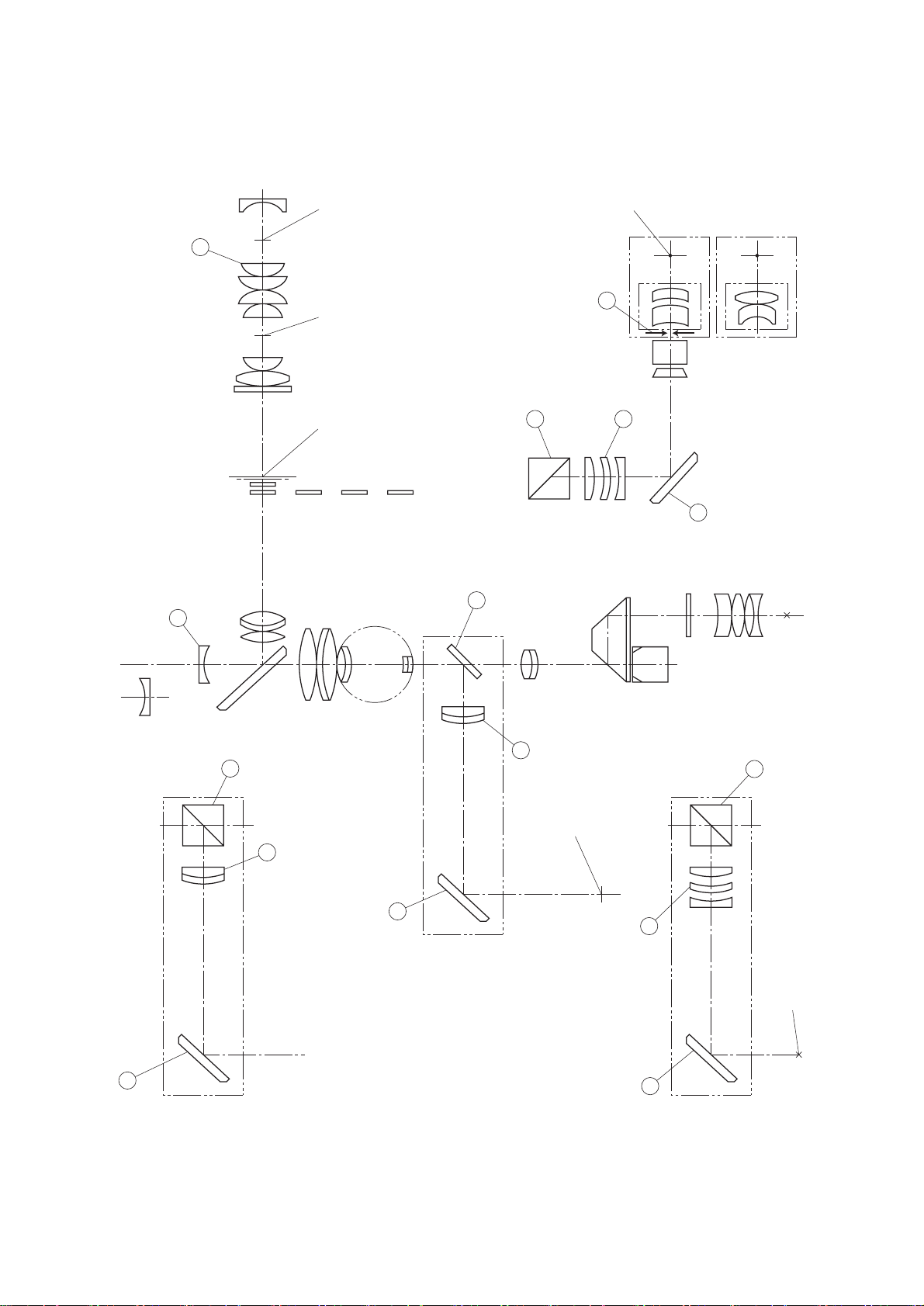
1-5 Names of Optical Parts and Functions......................................................................................................5
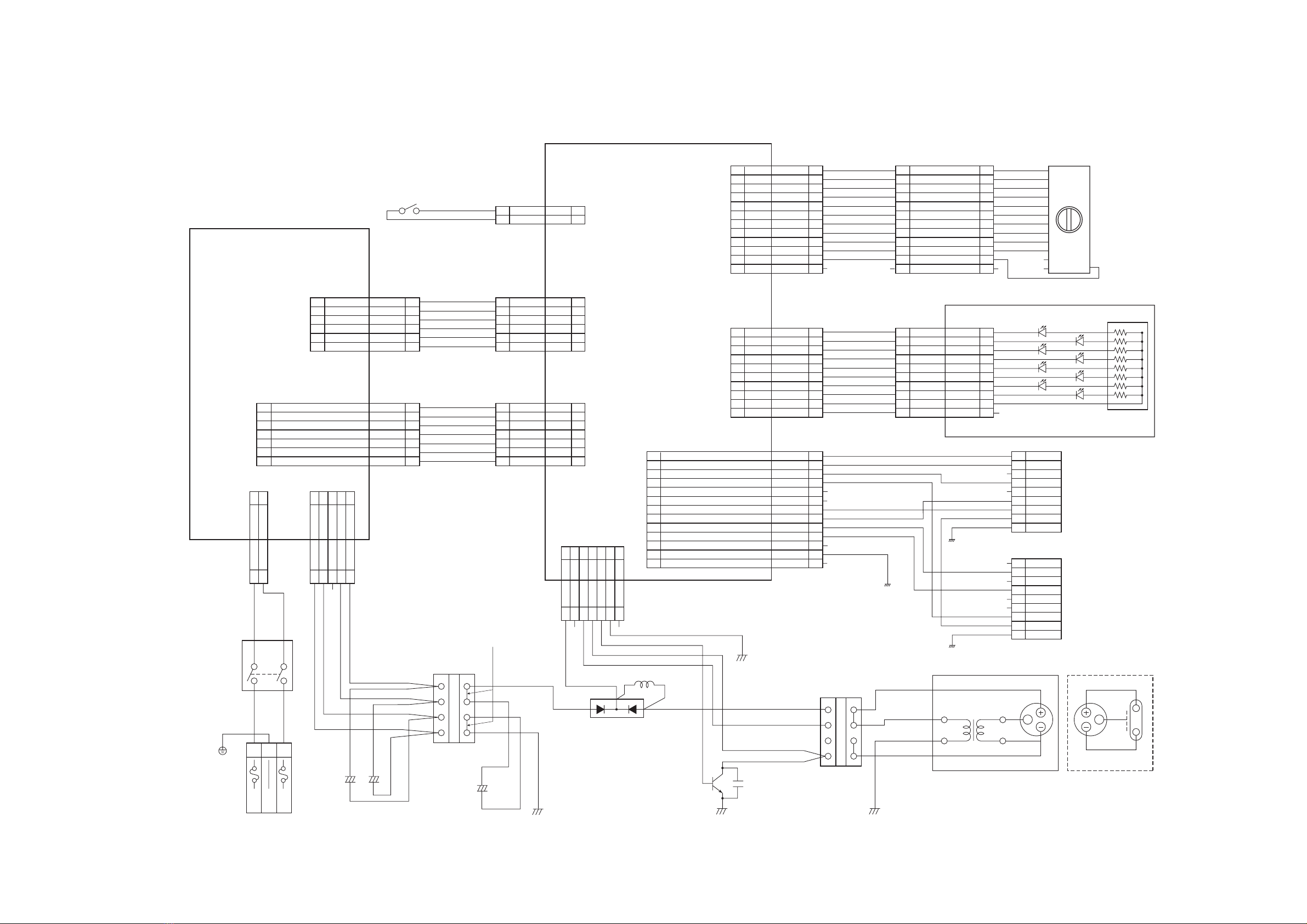
1-6 Electric System Wiring Diagram..............................................................................................................7
1-6-1 Power supply electric system wiring diagram (FD-21) ...................................................................7
1-6-2 Main unit electric system wiring diagram........................................................................................8
(1) SL-D7+SR-52+Nikon D1+FD-21 (IMAGEnet is connected)...........................................................8
(2) SL-D7+SR-52+Nikon D1+FD-21 (STAND ALONE is connected)..................................................9
(3) SL-D7+SR-53+Fuji S1Pro or S2 Pro+FD-21 (IMAGEnet is connected)........................................10
(4) SL-D7+TL-54+JVC KY-F70BU+FD-21 (IMAGEnet is connected) .............................................11
(5) SL-D7+DC-1+FD-21 (IMAGEnet is connected).............................................................................12
(6) SL-D7+DC-1(IMAGEnet is connected) ..........................................................................................13
2. REPAIR WORKS.................................................................................................................................14
2-1 Inspection................................................................................................................................................14
2-2 Adjustments............................................................................................................................................15
2-2-1 SR-52..............................................................................................................................................15
2-2-2 SR-53..............................................................................................................................................20
2-3 Order of Repairs......................................................................................................................................24
2-3-1 SR-52 Disassembly and assembly procedure.................................................................................25
2-3-2 Trouble shooting (Photographic unit) ............................................................................................26
2-3-3 Trouble shooting (Photographic power supply).............................................................................27
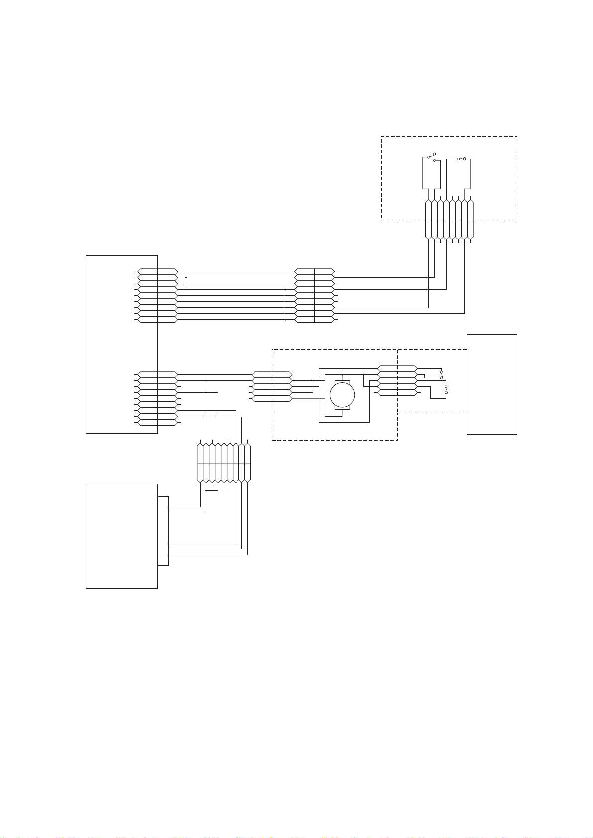
2-3-4 Wiring check ..................................................................................................................................33
2-3-5 Electric parts arrangement..............................................................................................................34
2-3-6 Electric parts number table.............................................................................................................35
2-4 Repair Tool List ......................................................................................................................................36
2-4-1 Special repair tool list.....................................................................................................................36
2-4-2 General repair tool list....................................................................................................................36
P-SLD_OPTION-0-0308-14

−1−
1. INTRODUCTION
Although this product features the same basic principles as the photographing device used with the SL-7F/7E,
8Z, the following main improvements have been performed: clear view and greater operational ease.
1-1 Features
•There are five types of camera (TV camera) to take a photograph: Nikon D1, Fuji S1 Pro or S2 Pro,
JVC KY-F70, SONY DXC-390 and Topcon DC-1. The user can select a camera.
The above are main features which are different from the photographing device used with the SL-7F/7E, 8Z.
1-2 Target Users of This Manual
This is optical equipment designed for ophthalmic testing. This manual is intended mainly for those experi-
enced in handling optical instruments, including repairs and adjustments. Those who have no experience in
those areas should take the repair course sponsored by Topcon.
1-3 How to Use This Manual and Precautions
1-3-1 Precautions for repair
(1) Carry out repair, assembly, disassembly and adjustment on optical systems in clean areas where no dust or
foreign matter will affect instrument performance.
(2) Refer to the SL-D7/accessories assembly and instruction manuals regarding assembly and inspection.
(3) Always carry out repairs according to the instructions in this manual, by using the specified materials and
tools.
(4) Compilation of instructions in this manual is based on the assumption that metal parts must be changed as
a single part and optical components by individual units.
(5) Refer to the service parts list for disassembly and assembly of parts not described in this manual.
(6) Never use grease or sealant except when specified by this manual.
(7) Order parts using the name and numbers found in the service parts list.
P-SLD_OPTION-0-0308-14

−2−
1-3-2 Repair procedure
Follow the procedures described in the flow chart below.
YES
NO
YES
NO
Repair is necessary.
Trouble has occurred.
Understand the trouble and its cause.
Normal
Repair
Inspection
Makeup
Packing
End
P-SLD_OPTION-0-0308-14

−3−
1-4 Part Names and Functions
Light volume
switching lever
Connector insertion port
Slit lamp
Photographic button
Xenon cord
Power switch
Slit lamp connecting connector
IMAGEnet connecting
connector
Illustration of connector insertion port
AC inlet
Light volume indicator
Control lever
• SL-D7
• Photographic power supply
P-SLD_OPTION-0-0308-14

−4−
• Components of the photographing device for digital camera
Note:The camera attachment and connecting cable are different according to the camera being used.
• Cameras to be connected
Cameras which can be connected to SL-D7 are as follows. The camera attachment and connecting cable are
different according to the camera.
Name Q'ty Name Q'ty
Xenon relay lens 1Photographic power supply 1
Background lighting (BG-3) 1Power cord (FD-21) 1
Photographic arm cover 1Cable support 1
Camera attachment and
connecting cable
(when SR-52 or SR-53 is
used)
1Mount adapter for camera 1
Xenon lamp 1
Recommended camera Camera attachment
Nikon D1 series Camera attachment SR-52
Fuji S1 Pro or S2 Pro Camera attachment SR-53
JVC KY-F70 TV relay lens TL-54
SONY DXC-390 TV relay lens TL-55
Topcon DC-1 Built-in type photographic unit
P-SLD_OPTION-0-0308-14

−5−
1-5 Names of Optical Parts and Functions
Filament position Camera mount reference surface
Xenon position
Slit position
Film position
SR-53 DC-1
SR-52
CCD
TL-54
TL-55
6
3
4
43
4
6
3
2
6 3
4
7
1
5
Photographic system
Photographic system
P-SLD_OPTION-0-0308-14

−6−
*Refer to the SL-D7 repair manual regarding other lenses.
Names of optical units Operation
Condenser lens Condensing/positioning is to be made for main bulb filament.
Quick return mirror Reflects the observed image and switches it to the camera side.
Photographic lens Lens for projecting the observed image
Focusing of the observed image
Reflection mirror Used to reflect the observed image.
Diffusion lens Increases the lighting field when taking a photograph of anterior eye sec-
tion.
Beam splitter Divides the image into two parts.
Forming lens Forms the image.
1
2
3
4
5
6
7
P-SLD_OPTION-0-0308-14

―7―
1-6 Electric System Wiring Diagram
1-6-1 Power supply electric system wiring diagram (FD-21)
CN5IMAGE NET SYNC 1
CN5GND 2
CN5GND 3
CN5JOY STICK IN 4
CN5R/L IN OUT 5
CN5R/L OUT 6
CN5IMAGE NET RELEASE
IMAGE NET RELEASE
7
CN5QUICK MIRROR 8
CN5GND 9
CN5GND 10
CN4
CN4
CN4
CN4
CN4
CN4
CN4
CN4
CN4
CN4
J4
J3
J5
J4
J3
J5
J4
J3
J5
J4
J3
J5
J4
J3
J5
J4
J3
J5
J4
J3
J5
J4
J3
J5
J4
J3
J5
J4
J3
J5
J3
J5
J3
J5
J5
1
2
3
4
5
6
7
8
9
10
1
2
3
4
5
6
7
8
9
10
CN15 CN19
CN15 CN19
CN15 CN19
CN15 CN19
CN15 CN19
CN15 CN19
CN15 CN19
CN15 CN19
CN15 CN19
CN15 CN19
1
2
3
4
5
6
7
8
9
2
3
4
5
6
7
8
9
10
1
2
3
4
5
6
7
8
9
CN16
CN16
CN16
CN16
CN16
CN16
CN16
CN16
CN16
CN17
CN17
CN17
CN17
CN17
CN17
CN17
CN17
CN17
1
2
3
4
5
6
7
8
9
1
2
3
4
5
6
7
8
9
10
CN5 11
CN5FG 12
CN5 13
1
2
3
4
5
6
7
8
9
10
11
12
13
EHR-13
VHR-7N
CN13
CN13
CN13
CN13
CN13
CN13
CN13
1
DISCHARGE 2
CHARGE CHK 3
4
CHARGE STOP 5
CHARGE/100 6
7
1
2
3
4
5
6
7
EHR-7 EHR-7
VAR-2
A8A-213-1
5TT10×2
NC-165
D1
2F1100G-100C
C5
5DMPPT-2J-475K
Terminal board 1
TS20-4P
Short bar S109
Terminal board
T2 TS20-4P
L1 200MH-10A
TR1
MG400J1US51
VHR-5N
CN2
CN2
CN2
CN2
CN2
CN2
CN2
1
2
3
4
5
6
7
1
2
3
4
5
6
7
CN6
CN6
CN6
CN6
CN6
CN6
CN6
1
2
3
4
5
6
7
1
2
3
4
5
6
7
5
4
3
CN10
2
1
CN11
CN11
CN12
CN12
CN12
CN12
CN12
1
2
5
4
3
2
1
1
2
CN14
CN14
CN14
CN14
CN14
CN14
24V 6PL
6PL
6PL
6PL
6PL
6PL
CN252
CN252
CN252
CN252
CN252
CN252
CN252
J1
J1
J1
J1
J1
J1
J7CN7
CN7 J7 1
2
1
2
J2
J2
J2
J2
J2
J2
J2
1
GND 2
5V 3
5V 4
GND 5
GND 6
1
2
3
4
5
6
VHR-6N VHR-6N
EHR-2
CN1
CN1
CN1
CN1
CN1
CN1
1
2
3
4
5
6
1
2
3
4
5
6
EHR-10 EHR-10
DE-9S-UL
IMAGE NET RELEASE
R/L
DE-9S-UL
B10B-EH MU03-4201×8
SW3 S22B1109D
CN3
CN3
CN3
CN3
CN3
CN3
CN3
CN3
CN3
CN3
CN3
CN3
1
2
3
4
5
6
7
8
9
10
CN21 CN20
CN21 CN20
CN21 CN20
CN21 CN20
CN21 CN20
CN21 CN20
CN21 CN20
CN21 CN20
CN21 CN20
CN21 CN20
CN21 CN20
CN21 CN20
Note:Set SW3 to contact 9.
1
2
3
4
5
6
7
8
9
10
1
2
3
4
5
6
7
8
9
10
11 1111
12
1
2
3
4
5
6
7
8
9
10
11
12 12
1
COM
2
3
4
5
6
7
8
9
10
11
1212
EHR-12 EHR-12 B12B-EH
AWG#18 BLU
AWG#18 BLK
AWG#18 RED
INNTERLOCK
AWG#26 YEL
AWG#26 YEL
AWG#18 RED
AWG#18 BLK
AWG#18 BLK
AWG#26 YEL
AWG#26 YEL
AWG#26 YEL
AWG#26 YEL
AWG#26 YEL
AWG#26 YEL
AWG#26 YEL AWG26 YEL
AWG26 YEL
AWG26 YEL
AWG26 YEL
AWG26 YEL
AWG26 YEL
AWG26 YEL
AWG26 YEL
AWG26 YEL
AWG26 YEL
AWG26 YEL
AWG26 YEL
AWG26 YEL
AWG26 YEL
AWG26 YEL
AWG26 YEL
AWG26 YEL
AWG26 YEL
AWG26 YEL
AWG26 YEL
AWG26 YEL
AWG26 YEL
AWG26 YEL
AWG26 YEL
AWG26 YEL
AWG26 YEL
AWG26 YEL
AWG22 GRY
AWG#18 BLU
AWG#18
BLU
AWG#18
BRN
AWG#18
BLU
AWG#14
Y/G
AWG#18
YEL
AWG#18
YEL
AWG#18 YEL FG
AWG#14 ORG
AWG#18
ORG
AWG#18
ORG
AWG#18
ORG
AWG#18 BLK
AWG#18 BLK
AWG#18RED
AWG#18 RED
AWG#18
BRN
AWG#18 GRY
AWG#18
ORG
AWG#14
GRY
AWG#14 ORG
AWG#18 YEL AWG#20 PPL
AWG#20 RED
AWG#20 YEL
AWG#20 GRY
AWG#18 RED
AWG#14 RED
FG
TT
LED8
LED6
LED4
LED2
LED1
LED3
LED5
LED7
POWER SUPPLY
FOR FD-21 FD-21Control PCB
SW PCB
LED PCB
TO IMAGE NET
TO SLIT LAMP
Xe LAMP UNITXe LAMP CABLE
J6
J6
J6
J6
J6
J6
J6
CN1
CN1
CN201
CN201
CN201
CN201
CN201
SW2
N
E
24
13
31
2
AWG#22 GRY
AWG#22 GRY
FG
FG
R/L
SW4
CN10
FG
C1 C2 C3
CN10
10A×2
330FK1800×3
L
1
2
3
4
+ +
FG FG
FG
+
1
2
3
4
Short bar
RKH1/4B8B2KΩJ
R1
R2
R3
R4
R5
R6
R7
R8
AWG26 YEL
AWG26 YEL
P-SLD_OPTION-0-0308-14

−8−
1-6-2 Main unit electric system wiring diagram
(1) SL-D7+SR-52+Nikon D1+FD-21 (IMAGEnet is connected)
P12 GND
GND
GND
JSTICK IN
R/L IN
J12
1
P12J12
2
P12J12
3
P12J12
4
P12J12
5
P12J12
6
P12J12
7
P12J12
8
P12J12
9
1
2
3
4
5
6
7
8
9
CN5P11 CN5P11 CN5P11 CN5P11 CN5P11 CN5P11 CN5P11 CN5P11 CN5P11
1
2
3
4
5
6
7
8
9
1
2
3
4
5
6
7
8
9
CN2CN5 CN2CN5 CN2CN5 CN2CN5 CN2CN5 CN2CN5 CN2CN5 CN2CN5
1
2
3
4
5
6
7
8
1
2
3
4
5
6
7
8
J13
J13
J13
J13
J13
J13
J13
J13
J13
P13
P13
P13
P13
P13
P13
P13
P13
P13
1
2
3
4
5
6
7
8
9
1
2
3
4
5
6
7
8
9
P17 J17
P17 J17
P17 J17
P17 J17
P17 J17
SYNC
GND
REL
GND
12V SOLENOID
1
2
3
4
5
1
2
3
4
5
J18 P18
NIKON D1 CORD
(4469186200)
J18 P18
J18 P18
J18 P18
J18 P18
1
2
3
4
5
1
2
3
4
5
P15
P15
P15
P15
P15
P15
P15
P15
P15
36
10
2
3
44
P14
P14
P14
P14
P14
P14
P14
P14
P14
1
2
3
4
5
6
7
8
9
1
2
3
4
5
6
7
8
9
SW1
SW5
SW6
SW2
QM NIKON D1
SL-D CABLE4
(4479074000)
CABLE VS200-SP
(4451027000)
44P
SL-D CABLE2
(4479072000) SL-D CABLE1
(4479071000)
SYNC
GND
R/L
REL
IMAGEnet
PC
FD-21
(Xe power supply)
TV relay lens for single-lens reflex
SR-52
SL-D Base unit
J・S SW R/L detection
SW
BF1011
BF1011
2
13
P-SLD_OPTION-0-0308-14

−9−
(2) SL-D7+SR-52+Nikon D1+FD-21 (STAND ALONE is connected)
P12 GND
GND
GND
JSTICK IN
R/L IN
J12
1P12J12
2P12J12
3P12J12
4P12J12
5P12J12
6P12J12
7P12J12
8P12J12
9
1
2
3
4
5
6
7
8
9
CN7P11 CN7P11 CN7P11 CN7P11 CN7P11 CN7P11 CN7P11 CN7P11 CN7P11
1
2
3
4
5
6
7
8
9
1
2
3
4
5
6
7
8
9
CN2CN5 CN2CN5 CN2CN5 CN2CN5 CN2CN5 CN2CN5 CN2CN5 CN2CN5
1
2
3
4
5
6
7
8
1
2
2
13
3
4
5
6
7
8
J13
J13
J13
J13
J13
J13
J13
J13
J13
P13
P13
P13
P13
P13
P13
P13
P13
P13
1
2
3
4
5
6
7
8
9
1
2
3
4
5
6
7
8
9
P17 J17
P17 J17
P17 J17
P17 J17
P17 J17
1
2
3
4
5
1
2
3
4
5
J18 P18 BF1011
BF1011
NIKON D1 CORD
(4469186200)
In the case of NIKON D1X STAND ALONE
J18 P18
J18 P18
J18 P18
J18 P18
1
2
3
4
5
1
2
3
4
5
SW1 SW2
NIKON D1
SL-D CABLE3
(4479073000)
SL-D CABLE2
(4479072000) SL-D CABLE1
(4479071000)
SYNC
GND
GND
R/L IN
REL
FD-21
(Xe power supply)
TV relay lens for single-lens reflex
SR-52
SL-D Base unit
J・S SW R/L detection
SW
QM
SYNC
GND
REL
GND
12V SOLENOID
SW5
SW6
P-SLD_OPTION-0-0308-14

−10 −
(3) SL-D7+SR-53+Fuji S1Pro or S2 Pro+FD-21 (IMAGEnet is connected)
P12 GND
GND
GND
JSTICK IN
R/L IN
J12
1
P12J12
2
P12J12
3
P12J12
4
P12J12
5
P12J12
6
P12J12
7
P12J12
8
P12J12
9
1
2
3
4
5
6
7
8
9
CN7P11 CN7P11 CN7P11 CN7P11 CN7P11 CN7P11 CN7P11 CN7P11 CN7P11
1
2
3
4
5
6
7
8
9
1
2
3
4
5
6
7
8
9
CN2CN5 CN2CN5 CN2CN5 CN2CN5 CN2CN5 CN2CN5 CN2CN5 CN2CN5
1
2
3
4
5
6
7
8
1
2
3
4
5
6
7
8
J13
J13
J13
J13
J13
J13
J13
J13
J13
P13
P13
P13
P13
P13
P13
P13
P13
P13
1
2
3
4
5
6
7
8
9
1
2
3
4
5
6
7
8
9
P17
P17
1
2
P15
P15
P15
P15
P15
P15
P15
P15
P15
36
10
2
3
44
P14
P14
P14
P14
P14
P14
P14
P14
P14
1
2
3
4
5
6
7
8
9
1
2
3
4
5
6
7
8
9
SW1 SW2
Fuji S1 Pro
or S2 Pro
SL-D CABLE5
(4479075000)
CABLE VS200-SP
(4451027000)
44P
SL-D CABLE2
(4479072000) SL-D CABLE1
(4479071000)
SYNC
GND
GND
R/L
REL
IMAGEnet
PC
FD-21
(Xe power supply)
TV relay lens for single-lens reflex
(BS)
J・S SW
SR-53
2
13
SL-D Base unit
R/L detection
SW
P-SLD_OPTION-0-0308-14

−11 −
(4) SL-D7+TL-54+JVC KY-F70BU+FD-21 (IMAGEnet is connected)
P12 GND
GND
GND
JSTICK IN
R/L IN
J12
1P12J12
2P12J12
3P12J12
4P12J12
5P12J12
6P12J12
7P12J12
8P12J12
9
1
2
3
4
5
6
7
8
9
CN7P11 CN7P11 CN7P11 CN7P11 CN7P11 CN7P11 CN7P11 CN7P11 CN7P11
1
2
3
4
5
6
7
8
9
1
2
3
4
5
6
7
8
9
CN2CN5 CN2CN5 CN2CN5 CN2CN5 CN2CN5 CN2CN5 CN2CN5 CN2CN5
1
2
3
4
5
6
7
8
1
2
3
4
5
6
7
8
J13
J13
J13
J13
J13
J13
J13
J13
J13
P13
P13
P13
P13
P13
P13
P13
P13
P13
1
2
3
4
5
6
7
8
9
1
2
3
4
5
6
7
8
9
P15
P15
P15
P15
P15
P15
P15
P15
P15
36
10
2
3
44
P14
P14
P14
P14
P14
P14
P14
P14
P14
1
2
3
4
5
6
7
8
9
1
2
3
4
5
6
7
8
9
SW1 SW2
JVC
KYF-70Bu
CABLE VS200-SP
(4451027000)
44P
SL-D CABLE2
(4479072000) SL-D CABLE1
(4479071000)
GND
GND
R/L
REL
IMAGEnet
PC
FD-21
(Xe power supply)
TV relay lens for 1/2
J・S SW
TL-54
2
13
SL-D Base unit
R/L detection
SW
P-SLD_OPTION-0-0308-14

−12 −
(5) SL-D7+DC-1+FD-21 (IMAGEnet is connected)
P12 GND
GND
GND
JSTICK IN
R/L IN
J12
1P12J12
2P12J12
3P12J12
4P12J12
5P12J12
6P12J12
7P12J12
8P12J12
9
1
2
3
4
5
6
7
8
9
CN2CN5 CN2CN5 CN2CN5 CN2CN5 CN2CN5 CN2CN5 CN2CN5 CN2CN5
1
2
3
4
5
6
7
8
1
2
3
4
5
6
7
8
J13
J13
J13
J13
J13
J13
J13
J13
J13
USB
ON
P6
P6
P6
P6
P6
P6
P6
P6
P6
1
2
3
4
5
6
7
8
9
1
2
3
4
5
6
7
8
9
SYNC
GND
GND
GND
REL
R/I
SW1 SW2
SL-D CABLE2
(4477072000)
IMAGEnet
PC
Monitor
DC-1
MAIN BOARD
(4479370000)
POWER UNIT
(4479371000)
KEYBOARD
(4479372000)
BATTERY UNIT
(4479388000)
FD-21
(Xe power supply)
P10
P10
P10
P10
51021-0400
P11
P11
P11
P11
J10
J6
J10
J10
J10
USB CN
51021-0400 IF CN XE_FLASH
EXT_TRIG
EYE_L/R
GND
POWER
D−
D+
GND
CVBS
GND
J11
J11
J11
J11
1
2
3
4
1
2
3
4
1
J17
J18 J19 J5
J8 J13 J7
J4
P17 (12V 1A) (+)
(−)
11 J17P17 22
2
3
4
1
2
3
4
J12 1
J12 2
51021-0200 VIDEO OUT CN
P12
1P12
2
J・S SW
Connected to J3 of PS power supply
2
13
CN7P11 CN7P11 CN7P11 CN7P11 CN7P11 CN7P11 CN7P11 CN7P11 CN7P11
1
2
3
4
5
6
7
8
9
1
2
3
4
5
6
7
8
9
SL-D CABLE1
(4477071000)
DC-1 IF CABLE
(4479383000)
DC-1 VIDEO CABLE
(4477038800)
DC-1 POWER CABLE
(4477038500)
DC-1 USB CABLE
(4479384000)
P5 1
P5 2
P5 3
P5 4
JTAG CN
P-MAIN1 CABLE
(4479386000)
P-MAIN2 CABLE
(4479387000)
SL-D Base unit
R/L detection
SW
P-SLD_OPTION-0-0308-14

−13 −
(6) SL-D7+DC-1(IMAGEnet is connected)
CN2CN5 CN2CN5 CN2CN5 CN2CN5 CN2CN5 CN2CN5 CN2CN5 CN2CN5
1
2
3
4
5
6
7
8
1
2
3
4
5
6
7
8
USB
ON
SW1 SW2
IMAGEnet
PC
Monitor
DC-1
MAIN BOARD
POWER UNIT KEYBOARD
BATTERY UNIT
(4479388000)
P10
P10
P10
P10
51021-0400
P11
P11
P11
P11
J10
J6
J10
J10
J10
USB CN
51021-0400 IF CN XE_FLASH
EXT_TRIG
EYE_L/R
GND
POWER
D−
D+
GND
CVBS
GND
J11
J11
J11
J11
1
2
3
4
1
2
3
4
1
J4
J18 J19 J5
J8 J13 J7
J4
P4 (12V 1A) (+)
(−)
11 J4P4 22
2
3
4
1
2
3
4
J12 1
J12 2
51021-0200 VIDEO OUT CN
P12
1P12
2
J・S SW
2
13
CN7P11 CN7P11 CN7P11 CN7P11 CN7P11 CN7P11 CN7P11 CN7P11 CN7P11
1
2
3
4
5
6
7
8
9
1
2
3
4
5
6
7
8
9
SL- D CABLE1
(4477071000)
DC-1 VIDEO CABLE
(4479385000)
DC-1 POWER CABLE
(4479382000) P-MAIN1 CABLE
(4479386000)
P-MAIN2 CABLE
(4479387000)
SL-DC-1 USB CABLE
(4479384000)
DC-1 IF CABLE
(4479388000) P5 1
P5 2
P5 3
P5 4
JTAG CN
SL-D Base unit
R/L detection
SW
Connected to J3
of PS power supply
P-SLD_OPTION-0-0308-14

−14 −
2. REPAIR WORKS
2-1 Inspection
Unit No. Item Checking method and judgment Adjustment and
repair methods Tools and tool
No.
SR-52 (1) Shift of screen
center Project the φ0.2 aperture on the test
bar and measure with the focus
positioning tool. [±1mm in up/
down/right/left]
Positioning of
optical axis for
SR-52
Focus position-
ing tool
(2) Blurring of
photographic
image
Project the φ10 aperture on the test
bar and use the focus positioning
tool to observe the focus of the
scale line and test bar surface.
Focusing for
SR-52 Focus position-
ing tool
SR-53 (1) Shift of screen
center Project the φ0.2 aperture on the test
bar and measure with the focus
positioning tool. [±1mm in up/
down/right/left]
Positioning of
optical axis for
SR-53
Focus position-
ing tool
(2) Blurring of
photographic
image
Project the φ10 aperture on the test
bar and use the focus positioning
tool to observe the focus of the
scale line and test bar surface.
Focusing for
SR-53 Focus position-
ing tool
DC-1 (1) Shift of cam-
era center Project the φ0.2 aperture on the test
bar and check by taking a photo-
graph. Replacement of
the unit
____
(2) Blurring of
camera Project the φ10 aperture on the test
bar and observe the focus by taking
a photograph. ____
1
1
1
1
P-SLD_OPTION-0-0308-14

−15 −
2-2 Adjustments
* Before carrying out adjustment, if the screw lock has been applied to any screw, dissolve it using Isoamyl
acetate.
2-2-1 SR-52
Illustration Procedure
(1) Focusing
The photographic focal point is poor and pho-
tographs are not clear.
Attach SR-52 to the main unit, turn the magni-
fication drum to 16× and project the φ10 aper-
ture on the test bar.
Remove the aperture frame (45520 1112).
Attach the focus positioning tool to the camera
mount unit.
Lower the return mirror with your finger and
make sure that the scale line on the focus posi-
tioning tool is fit to the focus on the test bar
surface.
16×
SR-52
Test bar
Aperture frame
(45520 1112)
Return mirror
Scale line
Focus positioning
tool
Test bar surface
◎Focused
◎Not focused
(Test bar surface cannot be seen.)
4
3
2
1
1
2
3
4
P-SLD_OPTION-0-0308-14

−16 −
Illustration Procedure
If the focus is off, remove the rubber cap,
loosen the hexagonal screw, and move the tool
up and down to where the focus is best. After
adjusting the position, apply the screw lock and
attach the rubber cap.
Project the φ0.2 aperture on the test bar and, as
looking into the focus positioning tool, check
the amount of shift.
When the optical axis is shifted, carry out posi-
tioning of optical axis.
* Refer to "(2) Positioning of optical axis" in P.17
and P.18.
Hexagonal screw
Screw lock
Rubber
cap
5
φ0.2 aperture
[Shift of optical axis:
Within 1mm]
Scale line on focus
positioning tool
6
5
6
7
P-SLD_OPTION-0-0308-14

−17 −
Illustration Procedure
(2) Positioning of optical axis
The photographic image is off in relation to the
observed image.
Attach SR-52 to the main unit, turn the magni-
fication drum to 16× and project the φ0.2 aper-
ture on the test bar.
Remove the aperture frame (45520 1112).
Attach the focus positioning tool to the camera
mount unit.
As looking into the focus positioning tool,
check the amount of shift.
Screen center shift: ±1mm
16×
SR-52
Test bar
Aperture frame
(45520 1112)
Return mirror
φ0.2 aperture
Scale line on focus
positioning tool
Focus
positioning tool
1
2
3
4
1
2
3
4
P-SLD_OPTION-0-0308-14

−18 −
Illustration Procedure
When the optical axis is shifted by 1mm or
more in the right-and-left direction:
Loosen the 3 screws CR2×4S and move the one
side of the mirror holder (1011) up and down
for adjustment.
After adjusting accuracy, tighten the 3 screws
CR2×4S securely and apply the screw lock.
When the optical axis is shifted by 1mm or
more in the up-and-down direction:
Loosen the 1 piece 1N2.6, adjust 1 piece
U2.6×6S and bring the optical axis to the cen-
ter.
CR2×4S:3 pcs.
Mirror holder
(1011)
5
1N2.6
Scale line
U2.6×6S:1 pc.
φ0.2 aperture
Adjust the mirror holder in the up-and-down direction
and bring it to the center in the right-and-left direction.
7
5
6
7
P-SLD_OPTION-0-0308-14
Table of contents
Popular Industrial Equipment manuals by other brands

Gehl
Gehl Dynalift DL Series Operator's manual

SMC Networks
SMC Networks MSZ Series manual

Mid-West Instrument
Mid-West Instrument 109 Series Installation and operating instructions

Storch
Storch Airless ST 1700 Translation of the original instruction

Autonics
Autonics LSC Series Communications manual

Matsing
Matsing MS-MBA-3-C4A3 instruction manual

Harmonic Drive
Harmonic Drive CSF-3 Series manual

Hoffmann&Hoffmann
Hoffmann&Hoffmann Dripmaster EDD-4SH user guide

Hellermann Tyton
Hellermann Tyton AT2000 CPK bench mount kit operating instructions

Oriental motor
Oriental motor NX Series operating manual

Alfalaval
Alfalaval M15 instruction manual

System air
System air SAVE-P VTR 250/B installation instructions