Topcon B111 Quick setup guide

B111
GNSS Receiver Board
Hardware Integration Guide

B111
Hardware Integration Guide
Part Number 1018409-01
Rev A
©Copyright Topcon Positioning Systems, Inc.
April, 2017
All contents in this manual are copyrighted by Topcon Positioning Systems, Inc. All rights reserved.

Table of Contents
Table of Contents
i
P/N: 1018409-01
Preface . . . . . . . . . . . . . . . . . . . . . . . . . . . . . . . . . . . . . . . . . . . . . . . . . . . . . . . . . iv
Terms and Conditions . . . . . . . . . . . . . . . . . . . . . . . . . . . . . . . . . . . . . . . . . . . . . . . . . . iv
Use . . . . . . . . . . . . . . . . . . . . . . . . . . . . . . . . . . . . . . . . . . . . . . . . . . . . . . . . . . . . iv
Copyrights . . . . . . . . . . . . . . . . . . . . . . . . . . . . . . . . . . . . . . . . . . . . . . . . . . . . . . . iv
Trademarks . . . . . . . . . . . . . . . . . . . . . . . . . . . . . . . . . . . . . . . . . . . . . . . . . . . . . . iv
Disclaimer of Warranty . . . . . . . . . . . . . . . . . . . . . . . . . . . . . . . . . . . . . . . . . . . . . . iv
License Agreement . . . . . . . . . . . . . . . . . . . . . . . . . . . . . . . . . . . . . . . . . . . . . . . . . v
Confidentiality . . . . . . . . . . . . . . . . . . . . . . . . . . . . . . . . . . . . . . . . . . . . . . . . . . . . v
Website; Other Statements . . . . . . . . . . . . . . . . . . . . . . . . . . . . . . . . . . . . . . . . . . . v
Safety . . . . . . . . . . . . . . . . . . . . . . . . . . . . . . . . . . . . . . . . . . . . . . . . . . . . . . . . . . v
Miscellaneous . . . . . . . . . . . . . . . . . . . . . . . . . . . . . . . . . . . . . . . . . . . . . . . . . . . . . v
About This Guide . . . . . . . . . . . . . . . . . . . . . . . . . . . . . . . . . . . . . . . . . . . . . . . . . . . . . v
Manual Conventions . . . . . . . . . . . . . . . . . . . . . . . . . . . . . . . . . . . . . . . . . . . . . . . . vi
Intended Audience and Qualification . . . . . . . . . . . . . . . . . . . . . . . . . . . . . . . . . . . . vi
Hardware and Firmware Versions . . . . . . . . . . . . . . . . . . . . . . . . . . . . . . . . . . . . . . . vi
Additional Documentation . . . . . . . . . . . . . . . . . . . . . . . . . . . . . . . . . . . . . . . . . . . . vi
Revision History . . . . . . . . . . . . . . . . . . . . . . . . . . . . . . . . . . . . . . . . . . . . . . . . . . . vii
Getting Technical Assistance . . . . . . . . . . . . . . . . . . . . . . . . . . . . . . . . . . . . . . . . . . . . . vii
Check This First! . . . . . . . . . . . . . . . . . . . . . . . . . . . . . . . . . . . . . . . . . . . . . . . . . . vii
Contacting Technical Support . . . . . . . . . . . . . . . . . . . . . . . . . . . . . . . . . . . . . . . . . vii
E-mail . . . . . . . . . . . . . . . . . . . . . . . . . . . . . . . . . . . . . . . . . . . . . . . . . . . . . . . vii
Website . . . . . . . . . . . . . . . . . . . . . . . . . . . . . . . . . . . . . . . . . . . . . . . . . . . . . . viii
Getting Acquainted . . . . . . . . . . . . . . . . . . . . . . . . . . . . . . . . . . . . . . . . . . . . . . . 1
Before You Start. . . . . . . . . . . . . . . . . . . . . . . . . . . . . . . . . . . . . . . . . . . . . . . . . . . . . . 1
Preventing Electrostatic Damage . . . . . . . . . . . . . . . . . . . . . . . . . . . . . . . . . . . . . . . 1
Checking the Package Contents . . . . . . . . . . . . . . . . . . . . . . . . . . . . . . . . . . . . . . . . 2
Handling of the B111 Board . . . . . . . . . . . . . . . . . . . . . . . . . . . . . . . . . . . . . . . . . . . 2
Installing TRU Software . . . . . . . . . . . . . . . . . . . . . . . . . . . . . . . . . . . . . . . . . . . . . 2
Overview . . . . . . . . . . . . . . . . . . . . . . . . . . . . . . . . . . . . . . . . . . . . . . . . . . . . . . . . . . . 3
Features . . . . . . . . . . . . . . . . . . . . . . . . . . . . . . . . . . . . . . . . . . . . . . . . . . . . . . . . 3
Board Layout and Main Hardware Components . . . . . . . . . . . . . . . . . . . . . . . . . . . . . 4
Block Diagram . . . . . . . . . . . . . . . . . . . . . . . . . . . . . . . . . . . . . . . . . . . . . . . . . . . . 5
Minimum Requirements to Run the B111 . . . . . . . . . . . . . . . . . . . . . . . . . . . . . . . . . 5
• • • • • •
Table of Contents

Table of Contents
ii
P/N: 1018409-01
Table of Contents
Hardware Components and Interfaces . . . . . . . . . . . . . . . . . . . . . . . . . . . . . . . . . . . . . . 6
Connector Types . . . . . . . . . . . . . . . . . . . . . . . . . . . . . . . . . . . . . . . . . . . . . . . . . . 6
Interface Connector . . . . . . . . . . . . . . . . . . . . . . . . . . . . . . . . . . . . . . . . . . . . . 6
GNSS Antenna Connectors . . . . . . . . . . . . . . . . . . . . . . . . . . . . . . . . . . . . . . . . . 6
Power System . . . . . . . . . . . . . . . . . . . . . . . . . . . . . . . . . . . . . . . . . . . . . . . . . . . . 7
Primary Power Rail . . . . . . . . . . . . . . . . . . . . . . . . . . . . . . . . . . . . . . . . . . . . . . 7
Backup Power Rail . . . . . . . . . . . . . . . . . . . . . . . . . . . . . . . . . . . . . . . . . . . . . . 7
USB Device Power Rail . . . . . . . . . . . . . . . . . . . . . . . . . . . . . . . . . . . . . . . . . . . 8
Power Controls . . . . . . . . . . . . . . . . . . . . . . . . . . . . . . . . . . . . . . . . . . . . . . . . . 8
PBTN . . . . . . . . . . . . . . . . . . . . . . . . . . . . . . . . . . . . . . . . . . . . . . . . . . . . . 8
PORESET . . . . . . . . . . . . . . . . . . . . . . . . . . . . . . . . . . . . . . . . . . . . . . . . . . 9
Sleep Mode . . . . . . . . . . . . . . . . . . . . . . . . . . . . . . . . . . . . . . . . . . . . . . . . . . . 9
STAT LED . . . . . . . . . . . . . . . . . . . . . . . . . . . . . . . . . . . . . . . . . . . . . . . . . . . . . . . 9
REC LED . . . . . . . . . . . . . . . . . . . . . . . . . . . . . . . . . . . . . . . . . . . . . . . . . . . . . . . . 10
GNSS Antenna . . . . . . . . . . . . . . . . . . . . . . . . . . . . . . . . . . . . . . . . . . . . . . . . . . . . 10
UART . . . . . . . . . . . . . . . . . . . . . . . . . . . . . . . . . . . . . . . . . . . . . . . . . . . . . . . . . . 11
USB . . . . . . . . . . . . . . . . . . . . . . . . . . . . . . . . . . . . . . . . . . . . . . . . . . . . . . . . . . . 12
CAN . . . . . . . . . . . . . . . . . . . . . . . . . . . . . . . . . . . . . . . . . . . . . . . . . . . . . . . . . . . 13
1PPS . . . . . . . . . . . . . . . . . . . . . . . . . . . . . . . . . . . . . . . . . . . . . . . . . . . . . . . . . . . 13
Event Marker . . . . . . . . . . . . . . . . . . . . . . . . . . . . . . . . . . . . . . . . . . . . . . . . . . . . . 13
SD/SDIO . . . . . . . . . . . . . . . . . . . . . . . . . . . . . . . . . . . . . . . . . . . . . . . . . . . . . . . . 14
General Purpose I/O . . . . . . . . . . . . . . . . . . . . . . . . . . . . . . . . . . . . . . . . . . . . . . . . 14
Function Control . . . . . . . . . . . . . . . . . . . . . . . . . . . . . . . . . . . . . . . . . . . . . . . . . . . 15
Firmware Features . . . . . . . . . . . . . . . . . . . . . . . . . . . . . . . . . . . . . . . . . . . . . . . . . . . . 15
Real-Time Kinematic Engine . . . . . . . . . . . . . . . . . . . . . . . . . . . . . . . . . . . . . . . . . . 15
Network-based RTK Techniques . . . . . . . . . . . . . . . . . . . . . . . . . . . . . . . . . . . . . . . . 16
Enhanced Positioning Engine (DION) . . . . . . . . . . . . . . . . . . . . . . . . . . . . . . . . . . . . 16
Satellite Based Augmentation System (SBAS) . . . . . . . . . . . . . . . . . . . . . . . . . . . . . . 17
Quartz Lock Loop . . . . . . . . . . . . . . . . . . . . . . . . . . . . . . . . . . . . . . . . . . . . . . . . . . 17
File System . . . . . . . . . . . . . . . . . . . . . . . . . . . . . . . . . . . . . . . . . . . . . . . . . . . . . . 17
Option Authorization File (OAF) . . . . . . . . . . . . . . . . . . . . . . . . . . . . . . . . . . . . . . . . 18
Design Guidelines . . . . . . . . . . . . . . . . . . . . . . . . . . . . . . . . . . . . . . . . . . . . . . . . . . . . . 19
Board Orientation and Mounting . . . . . . . . . . . . . . . . . . . . . . . . . . . . . . . . . . . . . . . 19
Pin Numbering and Connectivity to Target Hardware . . . . . . . . . . . . . . . . . . . . . . . . . 19
Cooling/Heating Requirements . . . . . . . . . . . . . . . . . . . . . . . . . . . . . . . . . . . . . . . . . 20
General Guidelines . . . . . . . . . . . . . . . . . . . . . . . . . . . . . . . . . . . . . . . . . . . . . . . . . 20
Power . . . . . . . . . . . . . . . . . . . . . . . . . . . . . . . . . . . . . . . . . . . . . . . . . . . . . . . . . . 20
USB . . . . . . . . . . . . . . . . . . . . . . . . . . . . . . . . . . . . . . . . . . . . . . . . . . . . . . . . . . . 20
SD/SDIO . . . . . . . . . . . . . . . . . . . . . . . . . . . . . . . . . . . . . . . . . . . . . . . . . . . . . . . . 20

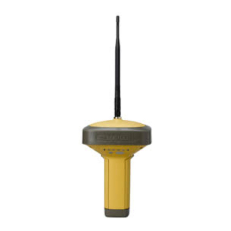
Table of Contents
iii
P/N: 1018409-01
Table of Contents
Approved SD Cards . . . . . . . . . . . . . . . . . . . . . . . . . . . . . . . . . . . . . . . . . . . . . . . . . 21
Product Compliance . . . . . . . . . . . . . . . . . . . . . . . . . . . . . . . . . . . . . . . . . . . . . . . . 21
Using Evaluation Board . . . . . . . . . . . . . . . . . . . . . . . . . . . . . . . . . . . . . . . . . . . . 22
Overview . . . . . . . . . . . . . . . . . . . . . . . . . . . . . . . . . . . . . . . . . . . . . . . . . . . . . . . . . . . 22
Connector and Component Locations . . . . . . . . . . . . . . . . . . . . . . . . . . . . . . . . . . . . . . . 23
Quick-Start to Run the B111 Installed on the Evaluation Board . . . . . . . . . . . . . . . . . . . . 24
B111 Evaluation Board Components and Connectors . . . . . . . . . . . . . . . . . . . . . . . . . . . . 26
GNSS Antenna Inputs . . . . . . . . . . . . . . . . . . . . . . . . . . . . . . . . . . . . . . . . . . . . . . . 26
Power Connectors . . . . . . . . . . . . . . . . . . . . . . . . . . . . . . . . . . . . . . . . . . . . . . . . . 27
Keys . . . . . . . . . . . . . . . . . . . . . . . . . . . . . . . . . . . . . . . . . . . . . . . . . . . . . . . . . . . 27
LEDs . . . . . . . . . . . . . . . . . . . . . . . . . . . . . . . . . . . . . . . . . . . . . . . . . . . . . . . . . . . 28
Jumpers . . . . . . . . . . . . . . . . . . . . . . . . . . . . . . . . . . . . . . . . . . . . . . . . . . . . . . . . 28
Interface Connector . . . . . . . . . . . . . . . . . . . . . . . . . . . . . . . . . . . . . . . . . . . . . . . . 29
Test Pads and Points . . . . . . . . . . . . . . . . . . . . . . . . . . . . . . . . . . . . . . . . . . . . . . . 31
UART Interfaces . . . . . . . . . . . . . . . . . . . . . . . . . . . . . . . . . . . . . . . . . . . . . . . . . . . 32
USB . . . . . . . . . . . . . . . . . . . . . . . . . . . . . . . . . . . . . . . . . . . . . . . . . . . . . . . . . . . 32
CAN . . . . . . . . . . . . . . . . . . . . . . . . . . . . . . . . . . . . . . . . . . . . . . . . . . . . . . . . . . . 33
SD Card . . . . . . . . . . . . . . . . . . . . . . . . . . . . . . . . . . . . . . . . . . . . . . . . . . . . . . . . . 33
Backup battery . . . . . . . . . . . . . . . . . . . . . . . . . . . . . . . . . . . . . . . . . . . . . . . . . . . . 34
1PPS . . . . . . . . . . . . . . . . . . . . . . . . . . . . . . . . . . . . . . . . . . . . . . . . . . . . . . . . . . . 34
Event Marker . . . . . . . . . . . . . . . . . . . . . . . . . . . . . . . . . . . . . . . . . . . . . . . . . . . . . 34
Specifications . . . . . . . . . . . . . . . . . . . . . . . . . . . . . . . . . . . . . . . . . . . . . . . . . . . . 35
Board Specifications . . . . . . . . . . . . . . . . . . . . . . . . . . . . . . . . . . . . . . . . . . . . . . . . . . . 35
Connector Specifications . . . . . . . . . . . . . . . . . . . . . . . . . . . . . . . . . . . . . . . . . . . . . . . . 39
Interface Connector . . . . . . . . . . . . . . . . . . . . . . . . . . . . . . . . . . . . . . . . . . . . . . . . 39
GNSS Antenna Connectors . . . . . . . . . . . . . . . . . . . . . . . . . . . . . . . . . . . . . . . . . . . 41
Mechanical and Schematic Drawings. . . . . . . . . . . . . . . . . . . . . . . . . . . . . . . . . . . . . . . . 42
B111 Dimensions . . . . . . . . . . . . . . . . . . . . . . . . . . . . . . . . . . . . . . . . . . . . . . . . . . 42
B111EVB Schematics . . . . . . . . . . . . . . . . . . . . . . . . . . . . . . . . . . . . . . . . . . . . . . . 43

Preface
iv
P/N: 1018409-01
• • • • • •
Preface
Thank you for purchasing this Topcon product. The materials available in this Manual (the “Manual”) have been
prepared by Topcon Positioning Systems, Inc. (“TPS”) for owners of Topcon products, and are designed to assist
owners with the use of the receiver and its use is subject to these terms and conditions (the “Terms and
Conditions”).
Terms and Conditions
Use
This product is designed to be used by a professional. The user should have a good knowledge of the safe use of
the product and implement the types of safety procedures recommended by the local government protection
agency for both private use and commercial job sites.
Copyrights
All information contained in this Manual is the intellectual property of, and copyrighted material of TPS. All rights
are reserved. Do not use, access, copy, store, display, create derivative works of, sell, modify, publish, distribute,
or allow any third party access to, any graphics, content, information or data in this Manual without TPS’ express
written consent and may only use such information for the care and operation of the receiver. The information
and data in this Manual are a valuable asset of TPS and are developed by the expenditure of considerable work,
time and money, and are the result of original selection, coordination and arrangement by TPS.
Trademarks
B111™, TRU™, Magnet™, Topcon® and Topcon Positioning Systems™ are trademarks or registered trademarks
of TPS. Windows® is a registered trademark of Microsoft Corporation. The Bluetooth® word mark and logos are
owned by Bluetooth SIG, Inc. and any use of such marks by Topcon Positioning Systems, Inc. is used under
license. Other product and company names mentioned herein may be trademarks of their respective owners.
Disclaimer of Warranty
EXCEPT FOR ANY WARRANTIES IN AN APPENDIX OR A WARRANTY CARD ACCOMPANYING THE PRODUCT, THIS
MANUAL AND THE RECEIVER ARE PROVIDED “AS-IS.” THERE ARE NO OTHER WARRANTIES. TPS DISCLAIMS ANY
IMPLIED WARRANTY OF MERCHANTABILITY OR FITNESS FOR ANY PARTICULAR USE OR PURPOSE. TPS AND ITS
DISTRIBUTORS SHALL NOT BE LIABLE FOR TECHNICAL OR EDITORIAL ERRORS OR OMISSIONS CONTAINED
HEREIN; NOR FOR INCIDENTAL OR CONSEQUENTIAL DAMAGES RESULTING FROM THE FURNISHING,
PERFORMANCE OR USE OF THIS MATERIAL OR THE RECEIVER. SUCH DISCLAIMED DAMAGES INCLUDE BUT ARE
NOT LIMITED TO LOSS OF TIME, LOSS OR DESTRUCTION OF DATA, LOSS OF PROFIT, SAVINGS OR REVENUE,
OR LOSS OF THE PRODUCT’S USE. IN ADDITION TPS IS NOT RESPONSIBLE OR LIABLE FOR DAMAGES OR COSTS
INCURRED IN CONNECTION WITH OBTAINING SUBSTITUTE PRODUCTS OR SOFTWARE, CLAIMS BY OTHERS,
INCONVENIENCE, OR ANY OTHER COSTS. IN ANY EVENT, TPS SHALL HAVE NO LIABILITY FOR DAMAGES OR
OTHERWISE TO YOU OR ANY OTHER PERSON OR ENTITY IN EXCESS OF THE PURCHASE PRICE FOR THE
RECEIVER.
Please read the terms and conditions carefully.

Preface
Preface
v
P/N: 1018409-01
License Agreement
Use of any computer programs or software supplied by TPS or downloaded from a TPS website (the “Software”)
in connection with the receiver constitutes acceptance of these Terms and Conditions in this Manual and an
agreement to abide by these Terms and Conditions. The user is granted a personal, non-exclusive, non-
transferable license to use such Software under the terms stated herein and in any case only with a single
receiver or single computer. You may not assign or transfer the Software or this license without the express
written consent of TPS. This license is effective until terminated. You may terminate the license at any time by
destroying the Software and Manual. TPS may terminate the license if you fail to comply with any of the Terms
or Conditions. You agree to destroy the Software and manual upon termination of the use of the receiver. All
ownership, copyright and other intellectual property rights in and to the Software belong to TPS. If these license
terms are not acceptable, return any unused software and manual.
Confidentiality
This Manual, its contents and the Software (collectively, the “Confidential Information”) are the confidential and
proprietary information of TPS. You agree to treat TPS’ Confidential Information with a degree of care no less
stringent that the degree of care you would use in safeguarding your own most valuable trade secrets. Nothing
in this paragraph shall restrict you from disclosing Confidential Information to your employees as may be
necessary or appropriate to operate or care for the receiver. Such employees must also keep the Confidentiality
Information confidential. In the event you become legally compelled to disclose any of the Confidential
Information, you shall give TPS immediate notice so that it may seek a protective order or other appropriate
remedy.
Website; Other Statements
No statement contained at the TPS website (or any other website) or in any other advertisements or TPS
literature or made by an employee or independent contractor of TPS modifies these Terms and Conditions
(including the Software license, warranty and limitation of liability).
Safety
Improper use of the receiver can lead to injury to persons or property and/or malfunction of the product. The
receiver should only be repaired by authorized TPS warranty service centers. Users should review and heed the
safety warnings in an Appendix.
Miscellaneous
The above Terms and Conditions may be amended, modified, superseded, or canceled, at any time by TPS. The
above Terms and Conditions will be governed by, and construed in accordance with, the laws of the State of
California, without reference to conflict of laws.
About This Guide
Welcome to the B111 Hardware Integrator Guide!
This manual is designed to be a comprehensive hardware guide to the B111 GNSS board. The material in this
manual describes the features, hardware components, installation, operation, and specifications of the B111
board.
In addition, this manual describes the features and functionality of the B111 Development Kit, which includes
the evaluation board, software, and all necessary cables.

Preface
Preface
vi
P/N: 1018409-01
Manual Conventions
This manual uses the following conventions:
Intended Audience and Qualification
This manual is intended for system engineers, system designers, and programmers who are integrating the
B111 board to their products to achieve GNSS positioning capabilities.
It is highly recommended that installation, commissioning, use, and maintenance of the B111 board are
preformed by personnel trained in electronics.
Hardware and Firmware Versions
The information in this manual corresponds to the following hardware and firmware versions:
•
B111 board hardware revision 6.7.
•
B111EVB board hardware revision 2.3
•
GNSS firmware version 5.1p1
Additional Documentation
The following documentation can be useful while working with the B111 board:
•
Maintenance Guide
(1020733-01) – explains how to maintain the B111 for various tasks using GRIL
commands.
•
GRIL Reference Manual
(27-040004-01) – contains an exhaustive description of the GNSS Receiver Interface
Language (GRIL) used to communicate and control a TPS receiver, including the B111.
•
TRU Help
– explains how to install, set up, and use the TRU software on desktop computers and hand-held
controllers.
Convention Description Example
Bold
Menu, or drop-down menu selection
File
Exit
(Click the
File
menu and click
Exit
)
Name of a dialog box or screen From the
Connection
screen...
Button or key commands Click
Finish
.
Mono
User supplied text or variable Type
guest
, and click
Enter.
Italic
Reference to another manual or help document Refer to the
Topcon Reference Manual
.
Further information to note about system configuration, maintenance, or setup.
Supplementary information that can have an adverse affect on system operation, system
performance, data integrity, measurements, or personal safety.
Notification that an action has the potential
to result in system damage, loss of data, loss of
warranty, or personal injury.

Preface
Preface
vii
P/N: 1018409-01
Revision History
Getting Technical Assistance
Should you have any questions about the B111 or experience any problems with this board, contact Topcon
OEM Solutions technical support for immediate and comprehensive assistance.
Check This First!
Before contacting Topcon OEM Solutions technical support, check the following:
•
Check all external board connections carefully to ensure correct and secure connections. Double check for
worn or defective cables.
•
Check all power sources to ensure their correct operation.
•
Check that the most current software is downloaded onto the computer and that the most current firmware
is loaded into the board. Check the Topcon
TotalCare
support website for the latest updates.
•
Check that the desired OAF options are enabled in the board.
Then, try the following:
•
Reset the board using TRU (
Tools
Reset Receiver
) or a GRIL command (
set,/par/reset,yes
).
•
Restore default settings using TRU (
Tools
Reset Parameters
) or a GRIL command (
init,/setup/
).
•
Clear the NVRAM using TRU (
Tools
Factory Reset
) or a GRIL command (
init,/dev/nvm/a
).
If the problem persists, see the following section for contact information.
Contacting Technical Support
If the troubleshooting hints and tips in this guide fail to remedy the problem, contact Topcon OEM Solutions
technical support.
E-mail
To contact Topcon OEM Solutions technical support via e-mail, use the oemsupp[email protected] electronic mail
address.
When e-mailing TPS technical support, provide the following information for better, faster service:
1. The board model and configuration settings. This information can be retrieved using
TRUInformationSave to File. Save the receiver’s output to a text file. Attach this file to the email
and submit it to Topcon OEM Solutions technical support.
2. The system/hardware specifications for the computer running TRU or a custom application; such as,
operating system and version, memory and storage capacity, processor speed, etc.
3. The symptoms and/or error codes/messages that precede and follow the problem.
4. The activities being tried when the problem occurs. If possible, include the exact steps being taken up to
when the error message or other problem occurs.
5. How regularly the problem occurs.
Generally, an OEM Solutions technical support representative will reply within 8 business hours or less,
depending on the severity of the problem.
Revision Date (yyyy-mmm-dd) Changes
A2017-Apr-03 Initial release of the B111 Hardware Integration Guide.
Do not attempt to repair equipment yourself. Doing so will void your warranty and may damage the
hardware.

Getting Acquainted
1
P/N: 1018409-01
• • • • • •
Getting Acquainted
The B111 board is the advanced and flexible multi-frequency GNSS receiver designed for OEM applications.
Building on the proven platform of the B110 and the success of the Vanguard™ chip, the B111 offers expanded
tracking capabilities while maintaining the B110 heritage of compact footprint and low power consumption.
Figure 1: B111 Board
Before You Start
Before using the B111 board, it is recommended to read the following sections. They were especially designed to
help you correctly integrate, setup, and operate the board.
Preventing Electrostatic Damage
The B111 board contains electronic components that are sensitive to electrostatic discharge (ESD). It can occur
suddenly and without any visible effect at any point throughout unpacking, installing, test, or operational
processes. If not properly controlled, a discharge of static electricity can badly affect or even damage the board.
To protect your board from the effects of static damage, implement the following methods of ESD control:
•
All manipulations with the board must be performed within an ESD-protected area. Such an area must meet
certain environment conditions and contain materials and equipment designed to minimize the damage from
ESD.
– The relative humidity must be maintained above a minimum of 30% in the ESD-protected area.
– The board must be kept and transferred in an ESD-protective container, for example, in a static-safe bag.
•
All personnel and equipment within the ESD-protected area must be properly grounded to ensure they are at
the same electrical potential.
– A wrist strap must be worn snugly against the user’s bare skin and be connected to the common point
ground. The wrist strap must also have a current limiting resistor with a minimum of one megohm
± 20 % resistance in the ground cord.
– When standing or walking around in your working area, it is highly recommended to use ESD protective
floors in conjunction with ESD control footwear or foot straps. All these items must also be properly
grounded to the common point ground.
For additional information about ESD control procedures visit the ESD Association website at www.esda.org.

Before You Start
2
P/N: 1018409-01
Getting Acquainted
Checking the Package Contents
When you unpack the B111 package, verify that you received all of the items listed in this section. Inspect the
B111 board and other items included to ensure that they have not been damaged during shipment. Verify that
all components are mounted on the board and appear intact.
If any of the items are missing or damaged, contact your Topcon dealer or Topcon technical support. See
“Contacting Technical Support” on page vii for contact information.
Retain the factory packaging for storage and/or in case there is a need to return the board.
The development kit (p/n 1006143-01) includes the following items:
•
B111EVB evaluation board with assembled standoffs and jumpers (p/n 05-100702-01LF)
•
two RF cables (p/n 14-004159-01LF)
•
standard null-modem cable (p/n 14-008086-01)
•
USB cable (p/n14-008081-01)
•
three jumpers (p/n 280060LF)
•
power supply with cable for North America (p/n 60815)
The B111 board is available as a standalone module in single unit and volume quantities. A standalone package
does not include the B111EVB board, cables, jumpers, and power supply.
Handling of the B111 Board
Handle the board by the edges only. Avoid touching the connector pins or any other electronic components of
the board.
Installing TRU Software
TRU is a Windows® software application designed for configuring GNSS receivers, including GNSS OEM boards,
modem boards, and Bluetooth modules.
Computer requirements for TRU are: Microsoft® Windows XP or newer and an RS-232C or USB port or
computer with Bluetooth wireless technology.
This software is available on
the Topcon
TotalCare
support website
to registered users.
After downloading the program from the website, extract the program’s files into a folder on your hard drive.
To install TRU on a PC:
1. Navigate to the TRU folder, and double-click TRU.zip.
2. Extract TRU.exe to a folder.
3. Double-click TRU.exe to run the installer, and then follow the on-screen instructions.
To uninstall TRU, use Add or Remove Programs in Microsoft® Windows.

Overview
3
P/N: 1018409-01
Getting Acquainted
Overview
Features
•Vanguard RF™
and
Vanguard™
chips
– A potent blend of the latest Topcon developments in digital and
analog processing that delivers
224 universal channels and up to 100 Hz measurement and position-
velocity-time update rates.
•
Future-proof signal tracking
– Receiving and processing GPS, Glonass, Galileo, BeiDou, and QZSS signals.
•
Multi-frequency RTK engine
– Powerful and robust RTK engine designed for single-base and network
operations.
•
DGNSS
– Ground-based and satellite-based submeter positioning using L1 code measurements.
•
Doppler filter
– Configurable bandwidth to minimize the noise and dynamic errors in the velocity output.
•
Velocity filter
– Second stage of velocity filtering for even smoother velocity output.
•
DION
– E
nhanced absolute positioning engine that allows you to use a single B111 to compute smoothed
and consistent position solutions.
•
HD2
– 2-D attitude determination using a pair of B111 boards.
•
1PPS
– Highly-reliable and very accurate reference timing source for external devices.
•
Event input
– Accurately record the time an external event occurs in the specified reference time.
•
Multipath mitigation
– Considerable mitigation of C/A code and carrier phase multipath errors using a
proprietary signal processing algorithm.
•
Quartz-Locked Loop (QLL)
– Permanent monitoring, detection, and isolation of the vibration-induced
frequency deviations for improved survivability and performance of a B111 in dynamic applications.
•
Adjustable phase-locked and delay-locked loops
– Optimize the tracking performance by adjusting the
parameters of the PLLs and DLLs.
•
Two RS-232C interfaces and two LVTTL interface
– Full-duplex, independent, and fully configurable
RS-232C and LVTTL serial ports with data rates of up to 460.8 Kbit/s.
•
High-speed USB 2.0 interface
– USB device for board configuration and control from a PC.
•
SD/SDIO interface
– Record raw data files to a compact, removable, and solid storage medium.
•
CAN interface without transceiver
– CAN bus connection that conforms to the CAN specification 2.0 A/B
and provides output of two NMEA 2000 messages.
•
On-board LED for tracking and operation awareness
– The board provides a STAT LED to view satellites
and position status.
•
Five dedicated GPIOs for external LEDs
– Control the behavior of STAT and REC LEDs with the five
dedicated GPIOs.
•
Command interface
– A rich set of commands, text and binary messages to control every part of your B111
board.
•
Dedicated pin for backup power source
– Implement a backup power source to ensure your settings and
other valuable date are instantly saved to the NVRAM where they are securely retained for future usage.
•
File system
– A part of the firmware is a Topcon file system that allows you to create, store, retrieve, and
delete the raw data files day by day with guaranteed file system integrity.
•
Automatic File Rotation Mode
– Automatically close and open tps files at scheduled, evenly spaced times.
•
Advanced Input Mode
– Enable any port to handle multiple formats of data simultaneously. Whether they
are GRIL commands or RTCM messages, AIM will recognize them and forward each to the proper decoder, all
through the same port.
•
Job Programming
– Configure time-based scheduling to run single or multiple GRIL commands for
automatic processing 24 hours a day, 7 days a week.
•
Output Duplication
– Duplicate the same output data to ports without making the board to generate these
data for each port.

Overview
4
P/N: 1018409-01
Getting Acquainted
•
Pass-through Mode
– Any board port becomes a transparent channel, which passes through all input data
to another port of your choice with or without interpretation of input data. Furthermore, a bidirectional
transparent channel which passes through all input data from one port to another and vice versa can easily
be established.
•
Universal Break Sequence
– Never have your board locked up because of unresponsive ports.
•
Sleep mode
– Minimize power consumption by putting the board in a dormant state and awake it up at a
specified GPS time.
Board Layout and Main Hardware Components
Figure 2 shows the B111 board layout and identifies major hardware components.
Figure 2: B111 Layout
Table 1 describes component functions and features.
5
6
1234
Table 1. B111 Components
No. Component
(Board Reference) Description
1Antenna connectors
(J100, J101)
The GNSS antenna connectors of Hirose H.FL Straight Though Hole are used for
connecting GNSS antennas.
For antenna requirements, see “GNSS Antenna” on page 10.
For connector details and pin descriptions, see “GNSS Antenna Connectors” on
page 41.
2Vanguard chip (U301) The Vanguard chip manages satellite measurement data from the RF section,
controls system memory, navigation processing and communication interfaces.
3, 6 RF section with
Vanguard RF chip
The radio frequency section receives, amplifies, and filters the incoming satellite
signals.
4Interface connector
(J400)
The interface connector is used for data transfer, board management, and power
distribution. For connector details and pin descriptions, see “Hardware Components
and Interfaces” on page 6 and “Interface Connector” on page 39.
5STAT LED (D302) The STAT LED displays the status of the tracked satellites. For blinking patterns and
their meaning, see “STAT LED” on page 9.

Overview
5
P/N: 1018409-01
Getting Acquainted
Block Diagram
A simplified hardware architecture of the B111 is shown in Figure 3.
Figure 3: B111 Block Diagram
Minimum Requirements to Run the B111
For a basic operation, the B111 requires a power supply with a constant voltage between +3.4 Vdc and
+4.5 Vdc at a loading current of 2 A, corresponding GND connections, a single UART interface, and an active
GNSS antenna connection.
The pins for the power supply, GND, and UART are located at the J400 connector as shown in Table 2. Pin no.1
is bottom-left and pin no.2 is top-left when you look at the connector with a metallic RF shield below.
The GNSS antenna connection is at the J101.
9
9
9
*166/
*166/
$QWHQQD6ZLWFK
$QWLQSXW
-
$QWLQSXW
-
57&
4XDUW]
N+]
67$7/('
56
7UDQVFHLYHU
,6/
8$5777/ 56$
56
7UDQVFHLYHU
,6/
56%
6'6',2
7UDQVFHLYHU
9
8$5777/
8$5777/
*3,2B/('*3,2B/('
*3,2*3,2
336
(9(17
86%
7UDQVFHLYHU
8$5777/
9
8/3,
ϲϬͲƉŝŶ
ĐŽŶŶĞĐƚŽƌ
)1B%71
325(6(7
3%71
9%$7
9&&,Q
9
86%3+<
3RZHU
0DQDJHU
8$5777/&$1
Table 2. Minimum Pin Connection
Signal Name Pin No. Pin Locations
PWR_IN 55, 57, 59
GND 56, 58, 60
RS_RXDA, RS_TXDA
RS_CTSA, RS_RTSA
35, 36
37, 38
3:5B,1
*1'
56B576$
56B7;'$
56B&76$
56B5;'$

Hardware Components and Interfaces
6
P/N: 1018409-01
Getting Acquainted
Hardware Components and Interfaces
Connector Types
The B111 uses a single interface connector and two GNSS antenna connectors.
Interface Connector
The interface connector J400 is used for data transfer, board management, and power distribution.
GNSS Antenna Connectors
The B111 uses two GNSS antenna J100 and J101 connectors for connecting GNSS antennas.
Table 3. Interface Connector
Manufacturer Hirose (http://www.hirose-connectors.com)
Manufacturer part number DF17(3.0)-60DS-0.5V(57)
Connector type Female
Number of rows 2
Number of contacts per row 30
Total number of contacts 60
Table 4. Mating Interface Connector
Manufacturer Hirose (http://www.hirose-connectors.com)
Manufacturer part number DF17(2.0)-60DP-0.5V(57)
Connector type Male
Number of rows 2
Number of contacts per row 30
Total number of contacts 60
Table 5. GNSS Antenna Connectors
Manufacturer Hirose (http://www.hirose-connectors.com)
Manufacturer part number H.FL-R-SMT(10)
Connector type Male
Table 6. Mating GNSS Antenna Connectors
Manufacturer Any
Connector type H.FL Female Jack

Hardware Components and Interfaces
7
P/N: 1018409-01
Getting Acquainted
Power System
The B111 operates various on-board components via three power rails:
•
Primary power rail
•
Backup power rail
•
USB device power rail
Primary Power Rail
The B111 uses the primary power rail to power Vanguard RF and Vanguard chips, system memory,
communication interfaces, antennas, and other electronic components. The primary power rail requires an input
voltage range from +3.4 Vdc to +4.5 Vdc at a loading current of 2 A and less than a 150 mV ripple voltage.
Connect all PWR_IN pins on the connector J400 to an external power supply and the corresponding GND pins
to a solid ground plane.
•
PWR_IN pins: 55, 57, 59
•
Corresponding GND pins: 56, 58, 60
After connecting the external power supply to the PWR_IN pins, an integrated power management IC (U303)
generates three different, continuous voltages 1.2 V, 1.8 V, and 3.3 V required by the various on-board
components.
Further Reading:
•
Pin descriptions in “Interface Connector” on page 39.
•
Design guidelines about power system integration in “Power” on page 20.
Backup Power Rail
The B111 board uses the backup power rail to supply the power to an internal real-time clock (RTC) and the
Non-Volatile Random Access Memory (NVRAM) when an external power supply has been discharged or
removed.
The RTC stores the time and date information while the NVRAM keeps data required for satellite tracking and
the current settings (such as elevation masks, serial port baud rate, etc.).
An on-board supervisory circuit monitors power supply conditions and automatically switches between the
primary power rail and the backup power rail when needed.
A 2-Amps power supply is required to handle a peak inrush current generated upon the board
startup.
The on-board power management IC filters out input noise and ripple, allowing you to use a loosely
regulated power supply provided the input voltage falls within an acceptable range.
Applying inappropriate voltages to power pins can damage the B111 board or make its operations
unstable, specifically:
– Exceeding the maximum input voltage can damage the B111 board or the connected equipment.
– Dropping below the minimum input voltage can cause improper performance of the B111 board or
damage to the B111 board.
A backup power source is not installed on the B111 board.

Hardware Components and Interfaces
8
P/N: 1018409-01
Getting Acquainted
To implement backup functionality, you need to connect a backup power source to VBAT pin (no. 51) of the
interface connector (J400). The backup power source must supply the voltage in the range of 1.8 V to 3.6 V.
The recommended backup power source is either the Tadiran Batteries’ lithium battery TL-4986/P or OmniCel
battery ER22G68. These batteries are rated at about 5 years of operation at typical consumption and ambient
temperature of 25° C.
The RTC and NVRAM draw approximately 14 μA at ambient temperature of 25° C when the voltage from an
external power supply is not applied. As long as the B111 is powered through the primary power rail, the RTC
and NVRAM are sourced from this rail and draw no current from the backup power rail.
If you do not need a backup power for the RTC and NVRAM, leave the VBAT pin unconnected.
Further Reading:
•
Pin descriptions in “Interface Connector” on page 39.
•
Design guidelines about power system integration in “Power” on page 20.
•
An example of how the backup battery connects to the evaluation board in “Backup battery” on page 34.
USB Device Power Rail
If you use the USB interface in device mode, you need to provide a 5V input on the USB_PWR pin (no. 25) of
the interface connector J400 to power the USB device interface of the B111.
If you do not use a USB device, leave the USB_PWR pin unconnected.
Further Reading:
•
Pin descriptions in “Interface Connector” on page 39.
•
Design guidelines about power system integration in “Power” on page 20.
Power Controls
PBTN
The PBTN* signal (pin no. 53 on J400) is an active-low input that powers up or down the B111 depending on
how long the signal is LOW (GND).
The PBTN* signal has an on-board pull-up resistor of 100 KOhm to 3.3 V and can be left unconnected if unused.
Further Reading:
•
Pin descriptions in “Interface Connector” on page 39.
•
Design guidelines about power system integration in “Power” on page 20.
Without a backup power supply connected, the B111 will reset all settings to default values and a
cold start condition will occur each time the B111 is power cycled.
Table 7. PBTN* Functions
Function Duration of LOW state Description
Power-up 1-3 seconds To power up the board, pull the signal LOW (GND) for more than 1
second and less than 3 seconds.
Power-down 3-10 seconds To power down the board, pull the signal LOW (GND) for more than 3
seconds and less than 10 seconds.

Hardware Components and Interfaces
9
P/N: 1018409-01
Getting Acquainted
PORESET
The PORESET* signal (pin no. 28 on J400) is an active-low input that causes the B111 board to enter the reset
state.
To reset the board, pull the signal LOW (GND) for at least 0.1 second.
The PORESET* signal has an on-board pull-up resistor of 10 KOhm to 3.3V and can be left unconnected if
unused.
Further Reading:
•
Pin descriptions in “Interface Connector” on page 39.
•
Design guidelines about power system integration in “Power” on page 20.
Sleep Mode
You can put the B111 board into a dormant state to minimize power consumption without turning off the board
completely. The board enters into sleep mode immediately after you send the corresponding GRIL command
and stays in this mode until you turn on the board manually or the board detects any activity on serial ports A
or B. You can also awaken the board from sleep mode at a specified GPS time using the wake-up option.
Further Reading:
How to enter and exit sleep mode in GRIL Reference Manual.
STAT LED
The B111 board provides one STAT LED (D302) that displays the status of the tracked satellites. Table 8 lists
the colors of the STAT LED blinks and their functions when the B111 in powered on.
When satellites are tracked, the sequence of blinks is as follows:
•
One green blink for each tracked GPS satellite.
•
One yellow blink for each tracked GLONASS satellite.
•
One cyan blink for each tracked GALILEO satellite.
•
One purple blink for each tracked BeiDou satellite.
•
One blue blink for each tracked QZSS satellite.
•
One red blink if the board is not tracking satellites or cannot compute a position. Otherwise, the board
produces a pause.
The STAT LED is available through GPIO1_LED...GPIO3_LED (nos. 40, 34, and 33) pins of the J400 connector.
Further Reading:
“General Purpose I/O” on page 14.
Table 8. STAT LED Color
STAT LED Color Description
Red No satellites being tracked.
Green The board is tracking GPS satellites; one blink per tracked GPS satellite.
Yellow The board is tracking GLONASS satellites; one blink per tracked GLONASS satellite.
Cyan The board is tracking GALILEO satellites; one blink per tracked GALILEO satellite.
Purple/magenta The board is tracking BeiDou satellites; one blink per tracked BeiDou satellite.
Blue The board is tracking QZSS satellites; one blink per tracked QZSS satellite.

Hardware Components and Interfaces
10
P/N: 1018409-01
Getting Acquainted
REC LED
The REC LED displays the data recording status of the SD card
and other memory related information, such as
memory initialization process, fault condition, etc., as shown in
Table 9. The REC LED is available through
GPIO4_LED (no. 32) and GPIO5 (no. 30) pins of the J400 connector.
Further Reading:
“General Purpose I/O” on page 14.
GNSS Antenna
The B111 board is primarily designed for use with Topcon active antennas. However, flexibility exists to
accommodate for custom active antennas.
Before connecting an active GNSS antenna, consider the following operating conditions:
•
For powering an LNA of the GNSS antenna connected to J100, the board supplies a voltage of +5.0 V to the
central pin with the maximum antenna current equal to 100 mA.
•
For powering an LNA of the GNSS antenna connected to J101, the board supplies a voltage of +3.3 V to the
central pin with the maximum antenna current equal to 100 mA.
•
Antenna’s LNA gain should be in the range of 26 dB to 34 dB.
•The total attenuation of a cable running between the antenna and the B111 should not be more than
10–12 dB at 1.6 GHz.
•
Antenna’s VSWR should be
≤
2:1.
•
Impedance should be 50 Ohm.
•
The J100 connector corresponds to the
ext
value of the GRIL parameter
/par/ant/rcv/inp
and to the
External
value of the
GNSS Antenna
setting on the
Antenna
tab of Tracking & Positioning in the TRU software.
The J101 connector corresponds to the
int
value of the GRIL parameter
/par/ant/rcv/inp
and to the
Internal
value of the
GNSS Antenna
setting on the
Antenna
tab of Tracking & Positioning in the TRU software.
•
The B111 uses only one connector at a time. If you attach each connector to a separate antenna
simultaneously, the board will by default use the satellite signals received from the antenna connected to J101.
You can activate the J100 connector using the GRIL command
%%set,/par/ant/rcv/inp,ext
. To revert
to the default connector J101, use the command
%%set,/par/ant/rcv/inp,int
.
•
Antenna connectors J100 and J101 provide the same tracking performance and you can choose whichever you
prefer. However, bear in mind that the antennas require different supply voltages as described earlier on this
page.
•
Do not connect J100 with J101.
Table 9. REC LED Color
REC LED Color Description
Blinking green Data recording is in progress. Each blink indicates that data is being written to the
storage medium. A maximum rate of the green blinks is 1 Hz.
Dark No data are being recorded or the files are being deleted.
Blinking yellow The storage medium is being initialized.
Solid red Fault condition with the memory/file system: no more memory, no storage
medium, no OAF for file logging, faulty memory or other hardware problem.
Topcon cannot guarantee the correct performance with other brands of GNSS antenna.
Do not use passive GNSS antennas with the B111.
Table of contents
Other Topcon Receiver manuals

Topcon
Topcon GRS-1 User manual

Topcon
Topcon GR-5 User manual

Topcon
Topcon HiPer II User manual

Topcon
Topcon GR-3 User manual

Topcon
Topcon UR-1 User manual

Topcon
Topcon Net-G5 User manual

Topcon
Topcon HiPer V User manual

Topcon
Topcon MR-2 User manual

Topcon
Topcon Pocket-3D User manual

Topcon
Topcon HiPer SR User manual

Topcon
Topcon HiPer XT User manual

Topcon
Topcon GR-3 User manual

Topcon
Topcon Net-G3A User manual

Topcon
Topcon GR-5 User manual

Topcon
Topcon GB-500 User manual

Topcon
Topcon IP-S3 HD1 User manual

Topcon
Topcon GR-5 User manual

Topcon
Topcon MC-i3 Assembly instructions

Topcon
Topcon MC-i3 User manual

Topcon
Topcon Net-G3 User manual