TERSUS Oscar Ultimate User manual

User Manual
Version V1.0-20190613
User Manual
For Oscar Ultimate
©2019 Tersus GNSS Inc. All rights reserved.
Sales & Technical Support:
More details, please visit www.tersus-gnss.com

User Manual for Surveying GNSS Receiver v1.0
1 / 66
Revision History
Version
Revision Date
Change Summary
1.0
20190613
Initial Release

User Manual for Surveying GNSS Receiver v1.0
2 / 66
Table of Content
Revision History....................................................................................................................... 1
Table of Content.......................................................................................................................2
List of Figures........................................................................................................................... 4
List of Tables............................................................................................................................ 7
Notices.......................................................................................................................................8
1. Introduction..............................................................................................................11
1.1 Overview.......................................................................................................... 11
1.2 Receiver Features.......................................................................................... 12
1.3 Devices in the package..................................................................................12
1.3.2 Battery and Charger.......................................................................................19
1.3.3 TC20 Controller...............................................................................................20
1.3.4 Other Accessories.......................................................................................... 24
2. General Operations................................................................................................28
2.1 Setting up Oscar............................................................................................. 28
2.1.1 Insert the battery............................................................................................. 28
2.1.2 Insert the SIM card......................................................................................... 30
2.1.3 Fix Oscar on a Tripod or Ranging Pole.......................................................31
2.2 Oscar Configuration....................................................................................... 33
2.2.1 Configure via Buttons.....................................................................................33
2.2.2 Configure via TC20 Controller...................................................................... 35
2.2.3 Configure via Web Interface......................................................................... 39
2.3 Data Download................................................................................................40
2.4 Firmware Upgrade..........................................................................................41
2.4.1 Wired Upgrade................................................................................................ 41
2.4.2 Wireless Upgrade........................................................................................... 42
1.3.1 Surveying GNSS Receiver...................................................................................13

User Manual for Surveying GNSS Receiver v1.0
3 / 66
2.5 Operations of TC20 Controller......................................................................43
2.5.1 Insert SIM card and T-Flash card.................................................................43
2.5.2 T-Flash Card....................................................................................................45
2.5.3 Using of Touch Screen.................................................................................. 46
3. Technical Specifications........................................................................................47
3.1 Surveying GNSS Receiver...................................................................................47
3.2 TC20 Controller...............................................................................................49
4. Typical Applications............................................................................................... 51
4.1 Base Station Operation..................................................................................51
4.2 Rover Operation..............................................................................................57
4.3 Static Survey................................................................................................... 63
4.4 Issues and Solutions...................................................................................... 65
5. Terminology.............................................................................................................66

User Manual for Surveying GNSS Receiver v1.0
4 / 66
List of Figures
Figure 1.1 Surveying GNSS Receiver – Ultimate............................................... 13
Figure 1.2 Surveying GNSS Receiver – Advanced............................................ 13
Figure 1.3 Surveying GNSS Receiver – Basic....................................................13
Figure 1.4 Buttons and Display on Oscar Ultimate......................................14
Figure 1.5 Bottom of Surveying GNSS Receiver................................................18
Figure 1.6 BN20 Battery.................................................................................. 19
Figure 1.7 CN20 Charger................................................................................ 19
Figure 1.8 CN20 Charger with two BN20 batteries..................................... 20
Figure 1.9 CN20 Charger Adapter..................................................................20
Figure 1.10 Four sides of TC20 controller.................................................... 22
Figure 1.11 TC20 Lithium battery................................................................... 23
Figure 1.12 TC20 Charger...............................................................................23
Figure 1.13 Mini USB cable.............................................................................23
Figure 1.14 GNSS Antenna Connector......................................................... 24
Figure 1.15 Height Measure Accessory........................................................ 24
Figure 1.16 410-470MHz radio antenna........................................................24
Figure 1.17 Extension pole..............................................................................25
Figure 1.18 30W Radio for Oscar...................................................................25
Figure 1.19 High Gain Radio Antenna...........................................................25
Figure 1.20 Telescopic pole for radio antenna............................................. 26
Figure 1.21 Ranging Pole................................................................................ 26
Figure 1.22 Bracket for TC20..........................................................................26
Figure 1.23 Carrying Case.............................................................................. 27
Figure 2.1 Open the battery cover..................................................................28
Figure 2.2 Put one battery in Oscar............................................................... 28
Figure 2.3 Insert the SIM card........................................................................ 30
Figure 2.4 Oscar as a base without radio antenna......................................31

User Manual for Surveying GNSS Receiver v1.0
5 / 66
Figure 2.5 Oscar as a rover without radio antenna..................................... 32
Figure 2.6 Device functional group................................................................ 35
Figure 2.7 Connect Oscar via Bluetooth....................................................... 36
Figure 2.8 Base configuration......................................................................... 37
Figure 2.9 Rover configuration........................................................................37
Figure 2.10 Link status of Base...................................................................... 38
Figure 2.11 Link status of Rover.....................................................................39
Figure 2.12 Connect Oscar to a computer....................................................40
Figure 2.13 Connect Oscar to a USB memory stick....................................41
Figure 2.14 Remove the back cover..............................................................43
Figure 2.15 Take off the back cover............................................................... 43
Figure 2.16 Put the SIM card in the holder................................................... 44
Figure 2.17 Insert T-Flash card.......................................................................44
Figure 2.18 Insert the back cover...................................................................45
Figure 2.19 Select USB function.................................................................... 46
Figure 3.1 Serial Data port of Oscar.............................................................. 49
Figure 4.1 Oscar as a Base – Network Mode.............................................. 51
Figure 4.2 Oscar as a Base – Internal Radio............................................... 52
Figure 4.3 Oscar as a Base –External 30W Radio...................................53
Figure 4.4 Base setting interface....................................................................55
Figure 4.5 Base configuration – TersusNetwork.......................................... 55
Figure 4.6 Base configuration – Radio.......................................................... 56
Figure 4.7 Base configuration – UART..........................................................56
Figure 4.8 Link status of Base using TersusNetwork.................................. 57
Figure 4.9 Oscar as a Rover – Network Mode.............................................57
Figure 4.10 Oscar as a Rover – Internal Radio............................................58
Figure 4.11 Rover setting interface................................................................ 60
Figure 4.12 Rover configuration – TersusNetwork...................................... 60
Figure 4.13 Rover configuration – PDANetwork..........................................61

User Manual for Surveying GNSS Receiver v1.0
6 / 66
Figure 4.14 Rover configuration – Radio...................................................... 61
Figure 4.15 Rover configuration – CORS Network......................................62
Figure 4.16 Link status of Rover using PDA network..................................62
Figure 4.17 Static Survey configuration........................................................ 64

User Manual for Surveying GNSS Receiver v1.0
7 / 66
List of Tables
Table 0.1 Document / Software used in this User Manual..........................10
Table 1.1 Usage of FN button for three versions......................................... 14
Table 1.2 Detailed description for LED indicators........................................15
Table 1.3 Possible LED flash patterns...........................................................16
Table 1.4 Receiver ports on the bottom side................................................ 18
Table 2.1 Devices to set Oscar as a base.....................................................31
Table 2.2 Devices to set Oscar as a rover.................................................... 32
Table 2.3 Button configuration for Oscar Ultimate and Advanced.............33
Table 2.4 Button configuration for Oscar Basic............................................34
Table 3.1 Surveying GNSS Receiver Performance............................................47
Table 3.2 Pin Definition of the serial data port............................................. 49
Table 3.3 TC20 technical specification.......................................................... 49
Table 4.1 Devices in Figure 4.1...................................................................... 51
Table 4.2 Devices in Figure 4.2...................................................................... 52
Table 4.3 Devices in Figure 4.3...................................................................... 53
Table 4.4 Devices in Figure 4.9...................................................................... 58
Table 4.5 Devices in Figure 4.10.................................................................... 58

User Manual for Surveying GNSS Receiver v1.0
8 / 66
Notices
FCC Notices
The Surveying GNSS Receiver has been tested and found to comply with
the radiated and conducted emission limits for a Class A digital device (FCC
Part 15B and Part 15C). The Class A limits are designed to provide
reasonable protection against harmful interference in a residential installation.
CE Marking
Tersus GNSS Inc. declares that Surveying GNSS Receiver is in compliance
with the essential requirements (radio performance, electromagnetic
compatibility and electrical safety) and other relevant provisions of
Radio Equipment Directive 2014/53/EU, Electromagnetic Compatibility
(EMC) Directive 2014/30/EU, and Low voltage (LVD) Directive 2014/35/
EU. Therefore the equipment is labeled with the following CE-marking.
The Declaration of Conformity may be obtained from Tersus GNSS Inc.

User Manual for Surveying GNSS Receiver v1.0
9 / 66
The following notices apply to all three versions of Oscar GNSS receivers.
Changes or modifications to this equipment not expressly approved
by Tersus could void the user’s authority to operate this equipment or
even has risk to damage the receivers.
Conventions
The following conventions are used in this manual:
!
Information that supplements or clarifies text.
A caution that actions, operation or configuration may lead to incorrect
or improper use of the hardware.
In this manual, all the commands to a receiver are in capital letters, which is
just for easy identification, the commands are not case-sensitive.
A warning that actions, operation or configuration may result in
regulatory noncompliance, safety issues or equipment damage.

User Manual for Surveying GNSS Receiver v1.0
10 / 66
Table 0.1 Document / Software used in this User Manual
Name
Description
Link
Log & Command
document
Document providing all the loggings
output from BX series receivers and
all the commands to the receivers
https://www.tersus-gnss.com/document
under GNSS OEM Board / User Manual
Tersus Tool Suite
Tersus Tools including
TersusDownload, TersusGeoPix,
TersusGNSSCenter, TersusUpdate,
TersusRinexConverter
https://www.tersus-gnss.com/software
Nuwa
Survey application running in the
Android platform, David, Oscar and
other NMEA devices can be
configured with Nuwa.
https://www.tersus-gnss.com/software/osc
ar-receiver
Mission Planner
A popular Ground Station software
http://firmware.ardupilot.org/Tools/Mission
Planner/
Support
If there is any problem and the information needed cannot be found in the
product documentation, request technical support using the Tersus website at
www.tersus-gnss.com, or mail to su[email protected]

User Manual for Surveying GNSS Receiver v1.0
11 / 66
1. Introduction
This chapter includes overview, receiver features, and devices in the package.
1.1 Overview
The Surveying GNSS Receiver is a new generation GNSS RTK
system. It supports calibration-free tilt compensation function which is
immune to magnetic disturbances, leveling pole is not required. Easy
configuration with 1.54 inch big interactive screen on Ultimate and Advanced
versions. With an internal high-performance multi-constellation and multi-
frequency GNSS board, the Surveying GNSS Receiver can provide high
accuracy and stable signal detection. The high-performance antenna can
speed up the time to first fix (TTFF) and improve anti-jamming
performance. The built-in large capacity battery is detachable, two batteries
support up to 16 hours of field work in RTK mode. The built-in UHF radio
module supports long distance communication. The rugged housing protects
the equipment from harsh environments.
The Surveying GNSS Receiver has three versions: Ultimate, Advanced, and
Basic. It provides selectivity for the requirement from different users.

User Manual for Surveying GNSS Receiver v1.0
12 / 66
1.2 Receiver Features
The Surveying GNSS Receiver has following features:
Supports constellations & frequencies
GPS L1, L2
Supports 410-470MHz UHF radio, 4G network, Wi-Fi, Bluetooth, NFC.
Tilt compensation without calibration, immune to magnetic disturbances.
Various working modes
16GB/8GB internal storage
Up to 16 hours working in RTK mode
IP67-rated dust- & waterproof enclosure, for reliability in harsh
environmental conditions
1.3 Devices in the package
The devices in the package may vary according to the customer requirement.
Here describes the major parts in the package.
1.3.1 Surveying GNSS Receiver
User Manual for Surveying GNSS Receiver v1.0
13 / 66
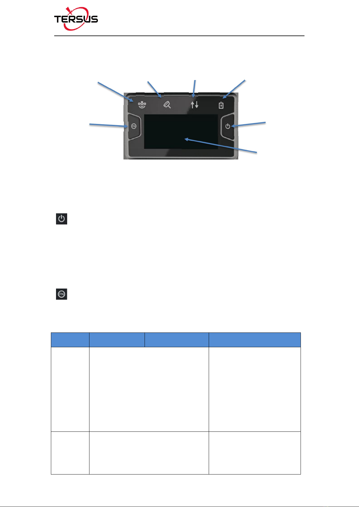
Figure 1.4 Buttons and Display on Oscar Ultimate
Buttons
There are two buttons on each version of Surveying GNSS Receiver
[]: Power ON/OFF button. When the device is off, long press it for 2
seconds to power on the receiver. When the device is on, long press it for 3
seconds to power off the Receiver. In addition, for Ultimate and Advanced
versions, in normal operation state this button is used as function selection
confirmation button working with the FN button which is explained below.
[]: Function (FN) button. This button has different functions for different
versions which is listed in the table below.
Table 1.1 Usage of FN button for three versions
FN button Ultimate Advanced Basic
Selecting /
Switching
On the Device Config page, press it once
to lead the cursor jump to the next row or
next page or previous page. When the
cursor stops at an item, pressing the
power button enters the sub menu of this
item for function selecting or return.
Switch static survey. After
pressing it for 3s to turn on the
static recording function. Then
press it to turn on the static
mode. Press and hold it for 3s
to turn off the static function.
Wake up Touch the power button or FN button to
wake up the OLED screen when the
OLED screen is light out.
NA
Satellite Tilt Compensation Correction Data Battery
Power
ON/OFF
Function
OLED Display

User Manual for Surveying GNSS Receiver v1.0
14 / 66
Combination Function of the two buttons
Press and hold the FN button, continuously touch the ON/OFF button 5 times
to reset the GNSS module and make it re-search the satellites. Detailed LED
flash status related to this operation refers to the LED flash patterns table.
LED Indicators
There are four LED indicators and one OLED display screen on Ultimate
version and Advanced version. There are six LED indicators on Basic version
of Surveying GNSS Receiver. The LESs on the front panel indicate
various operating conditions. The detailed LED Descriptions are shown in
the table below.
Table 1.2 Detailed description for LED indicators
LED
indicator
Ultimate
Advanced
Basic
Satellite
Green LED. Flashing every 5 seconds indicates that it is searching
satellites. After satellites are searched, it flashes N times every 5 seconds,
in which N indicates N satellites are found.
Tilt
compensation
Green & Yellow LED.
Steady green means
tilt compensation is
turned on.
N/A
N/A
Correction
data
Green and Yellow LED. Green indicates
correction data, and yellow indicates solution
status.
Green LED indicates
correction data.
Battery
Red LED. Steady red in normal operation. Slow flash indicates the battery
level is between 30% and 10%, fast flash indicates the battery level is
below 10% and reminds users to change battery.

User Manual for Surveying GNSS Receiver v1.0
15 / 66
Static Survey
N/A
Green LED indicates static survey mode.
Solution
status
N/A
N/A
Yellow LED. Steady yellow
indicates fixed solution,
flashing 1Hz indicates
floating solution, off light
for other solutions.
Bluetooth
N/A
N/A
Blue LED indicates
Bluetooth status.
LED Flash Patterns
The possible flash patterns of various states of receiver operation are listed in
the table below.
Table 1.3 Possible LED flash patterns
Receiver mode
Button operation
LED flash patterns
Receiver OFF
N/A
All LEDs are off.
Receiver ON
Long press power button for
2s
All LEDs are on, then all off, and
each LED starts to indicate current
status after initialization.
Low power
N/A
Battery LED flashes slowly.
Battery exhausting
N/A
Battery LED flashes fast.
Searching satellites
N/A
Satellite LED flashes every 5s
Satellites tracked
N/A
Satellite LED flashes N times every
5s, in which N is the quantity of
satellites tracked.
Receiving valid data
packet
N/A
Correction data LED flashes green at
1Hz

User Manual for Surveying GNSS Receiver v1.0
16 / 66
Fixed solution
N/A
Correction data LED is steady yellow
for Ultimate and Advanced versions,
Solution status LED is steady yellow
for Basic version.
Floating solution
N/A
Correction data LED flashes yellow
at 1Hz for Ultimate and Advanced
versions, Solution status LED
flashes yellow at 1Hz for Basic
version.
Reset GNSS module
Press and hold the FN
button, continuously touch
the ON/OFF button 5 times
The correction data LED and satellite
LED flash 3 times simultaneously,
the other LEDs remain in the original
state during this process.
Turn on static mode
for Basic version
Press FN button for 3s
Static LED flashes 3 times
continuously.
Turn off static mode
For Basic version
Press FN button for 3s
The correction data LED flashes 3
times continuously.
Firmware upgrade
N/A
All LEDs are on when downloading
firmware. All LESs flash continuously
3s simultaneously after the upgrade
is completed.
Note: N/A means Not Available.

User Manual for Surveying GNSS Receiver v1.0
17 / 66
Receiver Ports
The bottom of Oscar receiver is shown as below.
Figure 1.5 Bottom of Surveying GNSS Receiver
Table 1.4 Receiver ports on the bottom side
Icon
Connector
Name
Connections
Serial Data port
External power, RS-232 communication,
external radio
Mini USB port
Device, computer, USB drive
SIM
SIM slot
Micro SIM card
-
TNC port
Radio antenna
Serial Data port
TNC port
Mini USB port
SIM slot
User Manual for Surveying GNSS Receiver v1.0
18 / 66
1.3.2 Battery and Charger
Oscar equips smart lithium batteries which can detect electricity and display
the power level intelligently. The Surveying GNSS Receiver can also be
powered by external power source via serial data port. The built-in large
capacity battery is detachable, two batteries support up to 16 hours of field
work in RTK mode.
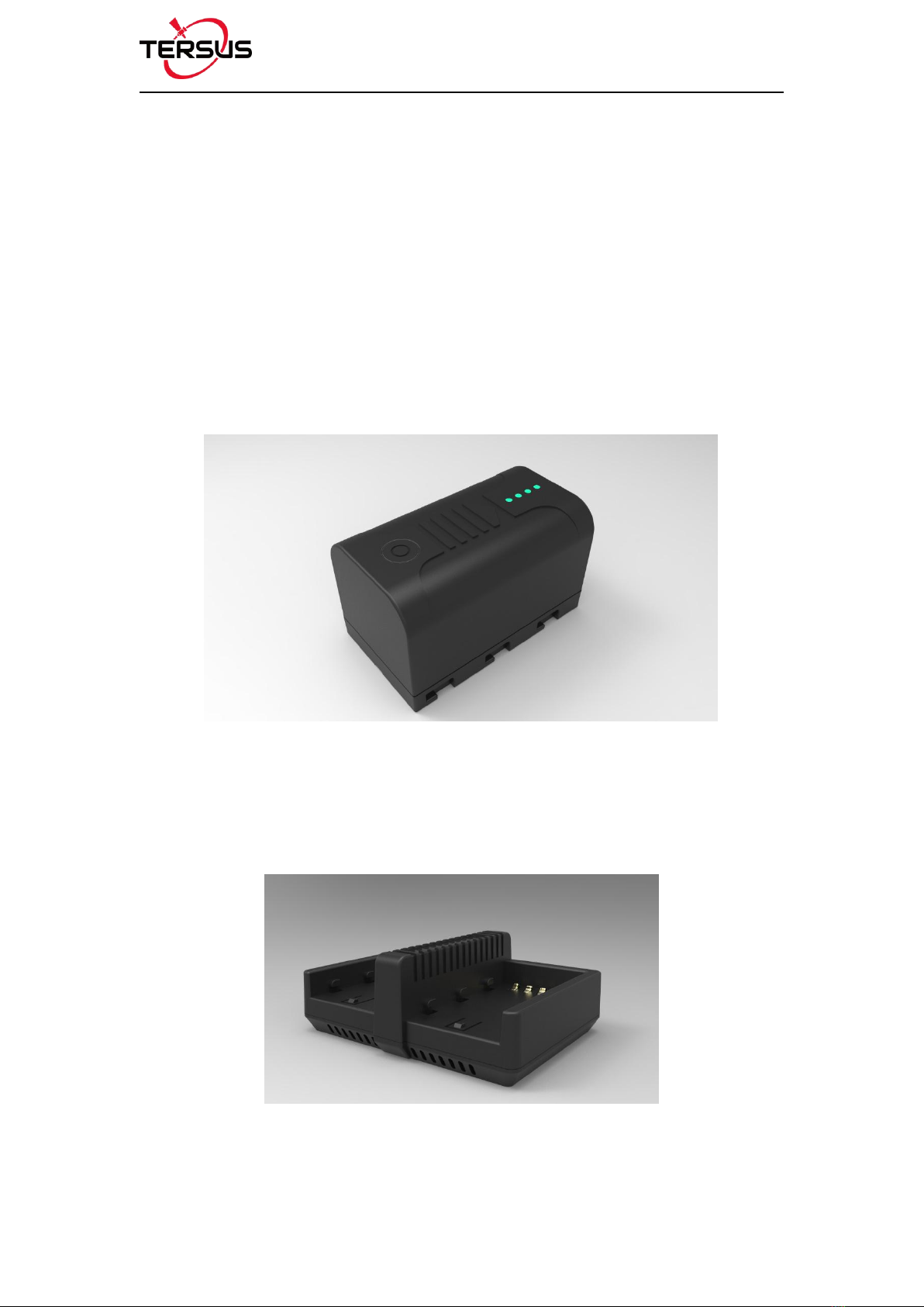
The BN20 battery is shown as below. Press the button on the top, it shows the
power level left to be consumed.
Figure 1.6 BN20 Battery
The CN20 Charger is able to charge two BN20 batteries at the same time
which is shown in the figures below.
Figure 1.7 CN20 Charger

User Manual for Surveying GNSS Receiver v1.0
19/ 66
Place two BN20 batteries in the slot of CN20 charger.
Figure 1.8 CN20 Charger with two BN20 batteries
Insert the DC Jack connector of the adapter to the CN20 charger, then make
the adapter plug in the local AC outlet (100~240V AC) to start charging.
Figure 1.9 CN20 Charger Adapter
Charge the battery completely before using it for the first time. Charging takes
approximately 3 hours per battery at room temperature. If the battery has been
stored for longer than three months, charge it before use.
Note: the product is not suitable for shipment with this adapter
Table of contents
Other TERSUS Receiver manuals

TERSUS
TERSUS David User manual

TERSUS
TERSUS GeoBee30 User manual

TERSUS
TERSUS PRECIS-TX204 User manual

TERSUS
TERSUS BX306 User manual

TERSUS
TERSUS Oscar User manual

TERSUS
TERSUS Oscar User manual

TERSUS
TERSUS Oscars User manual

TERSUS
TERSUS NeoRTK User manual

TERSUS
TERSUS BX316 User manual

TERSUS
TERSUS David User manual


