Topex BYTTON UMTS User manual

TOPEX PUBLIC SWITCHING S.A.
BYTTON UMTS
Advanced router for wireless broadband Internet access
using 3G technology
User’s Manual
31 October 2005

BYTTON UMTS User’s Manual (Preliminary)
TOPEX S.A. +40-21-232 04 http://www.topex.ro p. 1
Company profile
TOPEX is a group of Romanian companies, founded in 1990, by ten enthusiastic engineers
experienced in telecommunications. Its activity is directed to the research, development and
production of telecom equipment as well as service.
Very quickly, TOPEX become the most important manufacturer of communications solutions
for small to large companies as well as for telecommunications operators and providers in
Romania. Our company designs equipment for all existing mobile systems (GSM, CDMA),
including 3G technology.
TOPEX is represented all over Romania by a wide network of local distributors through which
the promotion, administration and product maintenance are running.
Due to our innovation power, authentic flexibility, real respect for our partners and the
secure solutions that we provide TOPEX extended its business worldwide. Currently TOPEX
delivers its products through its distributors to: Spain, France, Russia, UK, Turkey,
Netherlands, Greece, Republic of Moldova, Bulgaria, Nigeria, etc.
In order to achieve effective and flawless manufacturing for its products, TOPEX has
carefully organized its Research and Development Department along with its production
facility. This allows TOPEX to have maximum control of all the processes involved in the
complex operations related to high-technology electronic manufacturing.
Currently, 25 percent of Topex personnel are part of R&D Department and their number is
increasing.
TOPEX also considered the training and the service as an integral part of the solutions it
provides. Therefore, comprehensive training sessions are held at the Topex factory,
complimentary for the company’s clients. Service is also provided via Internet, as all Topex
solutions are designed especially to allow this, at the lowest cost.
TOPEX has implemented the quality management system according ISO9001 standard
certified by SRAC since 1997, respectively by IQNET since 2002. In TOPEX become a
sector member of I.T.U. (International Telecommunication Union).
The main lines of products of our company are:
-GSM/GPRS/UMTS interfaces (analog, ISDN BRI and PRI, GSM VoIP gateway)
-advanced interfaces (UMTS voice/data, LAN, CDMA router, GPS, miniature)
-VoIP gateways (basic, GSM/CDMA, advanced)
-Custom systems for special applications in communications, such as VCSS (air traffic
control, railway dispatching center)
-Phone exchanges (analog, digital, private/rural, IP PBX, protocol converters)
For more details please visit our website: www.topex.ro

BYTTON UMTS User’s Manual (Preliminary)
TOPEX S.A. +40-21-232 04 http://www.topex.ro p. 2
Congratulations!
Thank you for buying the TOPEX Bytton product and congratulation for your wise choice.
BYTTON UMTS has the following features:
•Voice and data interface
– simultaneous voice and data transmission
-- use a single mobile connection for both voice calls and data transfers, while browsing or
downloading you can still make important phone calls
•High Throughput
– download data rates up to 384 Mbps
– wireless data transfers between clients up to 54 Mbps
– wired data transfers between clients up to 100 Mbps
•High Security
– stateful packet inspection firewall for Internet connection
– 128 bits encryption for wireless clients
– secure HTTP (HTTPS) access to configuration and Hotspot pages
•Ease of Use
– true Plug-and-Play functionality*
– web based configuration interface
– embedded server for dynamic IP configuration of the clients (DHCP)
– embedded server for static IP configuration of the clients (IP-PnP)
– embedded transparent HTTP/HTTPS proxy
– automatic e-mail server redirection
•Advanced Internet Connection Management
– automatic connection establishment on traffic detection
– automatic disconnection on lack of traffic
– the connection can be initiated remotely when required**
– complete network address translation (NAT) support
•Hotspot Service
– allows immediate creation of wireless Internet hotspots
– dual mode login allows users to use either an account or a PIN from a prepaid card
– automatic injection of e-mail with login instructions for new users
– RADIUS based remote authentication and accounting
* : IP Plug and Play technology means that new users and IP configurations such as Private IP and
Static IP or DHCP, gateway or Proxy are automatically recognized, there is no need for users to re-
configure their PCs, notebooks or PDAs. This translates into instant wireless Internet connection for
multiple local users, wireless (WiFi) or wired (10/100 Ethernet cables).
** : needs voice activation of the UMTS terminal from the 3G carrier

BYTTON UMTS User’s Manual (Preliminary)
TOPEX S.A. +40-21-232 04 http://www.topex.ro p. 3
•Video Surveillance Service
– allows video monitoring using either an USB web camera or an IP camera***
– web based viewer of the video stream
– supports multiple cameras
•Easy Firmware Updating
– firmware updates can be downloaded for free****
– automatic update process using the web configuration interface
•Low Power Consumption (less than 10 Watts)
- the low power consumption means reduced heat dissipation, hence no cooling fans, no
moving parts, you get higher reliability and no noise
•Two USB 2.0 ports
- intended primary for web cam connection
- may be also used to connect an external 3G modem
- further developments will allow connection of peripherals, external hard disk drives, card
readers, etc. These storage devices will be shared with users from WLAN or Internet.
•Fully Mobile Internet Access Solution
- it is wireless on the LAN side due to embedded WiFi 802.11g/b Access Point
-also wireless on the WAN side due to CDMA UMTS connection
-the remote configuration via browser means no cables at all are required!
•Multiple mobile networks supported
-the embedded modem is for GSM/GPRS/UMTS
-this way you may use any mobile network available in your area: classic GSM (2G) in the
900/1800 MHz frequency band, GPRS 900/1800 (2,5G) or 3G UMTS on 2100 MHz
•Two phone interfaces, FXO and FXS for versatility
- the FXS interface can be used for connecting to an analog trunk of the PBX or directly to a
standard phone
-the FxO interface can be used for connecting to a local extension of the PBX. This is very
useful when all the trunks of the phone exchange are already used.
•SIM based
-you can easily change the subscription to the mobile network
-when you go from one 3G carrier to another, you only change the SIM, not the modem
*** : USB and wireless or wired IP cameras are available on demand, features varies with different
models
**** : firmware update files are monthly published on our website

BYTTON UMTS User’s Manual (Preliminary)
TOPEX S.A. +40-21-232 04 http://www.topex.ro p. 4
Table of Contents
1. Introduction.......................................................................................................................................................... 5
3G networks......................................................................................................................................................... 5
WiFi...................................................................................................................................................................... 5
System Requirements.......................................................................................................................................... 5
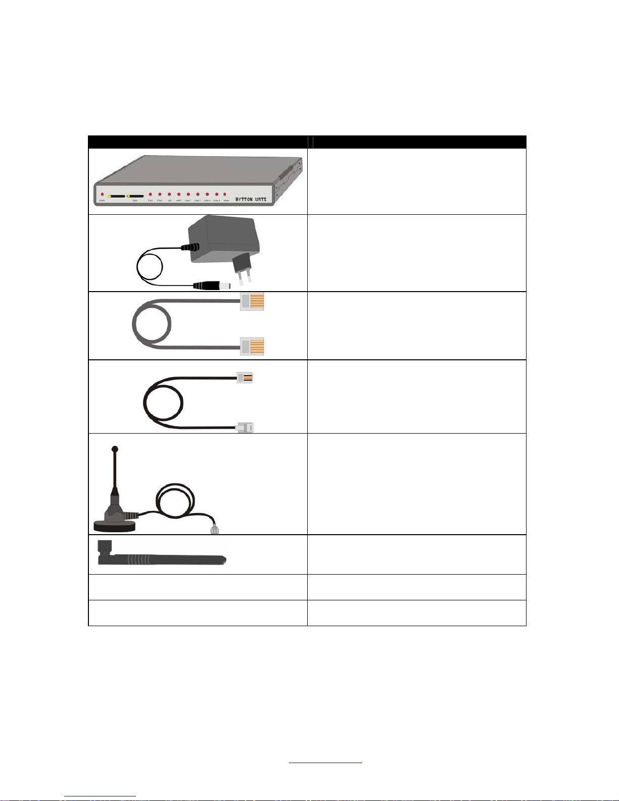
2. Package Content................................................................................................................................................. 6
3. What is BYTTON UMTS?.................................................................................................................................... 7
4. Installation ........................................................................................................................................................... 9
4.1 Establishing the best location......................................................................................................................... 9
4.2 Mounting (hardware installation).................................................................................................................... 9
4.3 Identification of connectors ............................................................................................................................ 9
4.4. Connecting the cables................................................................................................................................. 10
4.5. Connecting the phone cables:..................................................................................................................... 12
4.6. Configuring and installing the SIM card ...................................................................................................... 13
4.7. Connecting the external antennas .............................................................................................................. 15
4.8. Power up..................................................................................................................................................... 16
4.7 Status indicators ......................................................................................................................................... 16
5. Configuration..................................................................................................................................................... 17
5.1 Using the web interface................................................................................................................................ 17
5.2 LAN.............................................................................................................................................................. 20
5.2.1. IP Settings............................................................................................................................................ 20
5.2.2. WiFi Settings........................................................................................................................................ 20
5.2.3. Commit................................................................................................................................................. 23
5.2.4. DHCP................................................................................................................................................... 23
5.3 WAN............................................................................................................................................................. 24
5.3.1. Type ..................................................................................................................................................... 24
5.3.2. Ethernet................................................................................................................................................ 24
5.3.3. PPPoE.................................................................................................................................................. 25
5.3.4. PPP...................................................................................................................................................... 26
5.3.5. DDNS:.................................................................................................................................................. 27
5.4 ROUTING .................................................................................................................................................... 28
5.4.1. Firewall................................................................................................................................................. 28
5.4.2. Static Routes........................................................................................................................................ 29
5.5 SYSTEM...................................................................................................................................................... 30
5.5.1. Status................................................................................................................................................... 31
5.5.2. Logs...................................................................................................................................................... 32
5.5.3. Update.................................................................................................................................................. 32
5.5.4. Password.............................................................................................................................................. 33
5.5.5. Defaults................................................................................................................................................ 33
5.5.6 Save...................................................................................................................................................... 35
5.5.7. Load ..................................................................................................................................................... 35
5.6 SIM .............................................................................................................................................................. 35
5.6.1. SIM Settings......................................................................................................................................... 36
5.6.2. SIM Status............................................................................................................................................ 36
5.7 SMS............................................................................................................................................................. 37
5.7.1. SMS Settings........................................................................................................................................ 37
5.7.2. SMS Read............................................................................................................................................ 38
5.7.3 SMS Send................................................................................................................................................. 39
5.8. PHONE....................................................................................................................................................... 39
5.8.1. Phone Connections for BYTTON UMTS .............................................................................................. 39
5.8.2. Line Settings......................................................................................................................................... 41
5.9 WEBCAM..................................................................................................................................................... 43
5.10 OV511 compatible cameras....................................................................................................................... 44
5.11 Optimizing WiFi Performances................................................................................................................... 44
5.11.1. Network physical configuration........................................................................................................... 45
5.11.2. Range................................................................................................................................................. 45
6. Technical Specifications.................................................................................................................................... 46
7. Operating Environment...................................................................................................................................... 46
8. Applications....................................................................................................................................................... 47
a) Wireless gateway/firewall/router using the UMTS network............................................................................ 47
b) Broadband router with wireless local connections......................................................................................... 48
c. Remote video surveillance with camera......................................................................................................... 48
9.Topex 3G Family of Products.......................................................................................................................... 49
10. Glossary .......................................................................................................................................................... 50

BYTTON UMTS User’s Manual (Preliminary)
TOPEX S.A. +40-21-232 04 http://www.topex.ro p. 5
1. Introduction
3G networks
New research in the field of telecommunications has led to the extension of the range of
services provided to the users, especially in the mobile communications networks. Today, 3G
mobile networks dominate the world market. The TOPEX Group is promoting the advanced
facilities provided by the CDMA or UMTS wireless network, by manufacturing several ranges
of products that including BYTTON UMTS.
These 3G wireless devices are new electronic equipment, of compact size, which use
an updated design and are easy to mount and install. The economic benefits of Topex user-
network interfaces are considerable. By using these services you can perform several
activities at the same time, such as data transmission, Internet connection, voice call,
checking of geographical coordinates by GPS.
The high data transfer speed specific to the third generation communications network
leads to an increased efficiency of information transmission, while the real time access to
data and information means important savings of time and money.
UMTS, Universal Mobile Telecommunications Service, part of the IMT-2000 initiative,
is a 3G standard supporting a theoretical data throughput of up to 2 Mbps. The UMTS
system maintains compatibility with widely used GSM/GPRS networks, but assures higher
quality and faster data transfer, thereby enabling the development and better use of services
and contents, both already developed and new ones. UMTS is based upon wideband CDMA
(WCDMA) technology. CDMA digitally encoded technology ensures connections with
exceptional security. CDMA virtually eliminates cloning and other types of fraud because of
the 4.4 trillion codes used, while the spread spectrum signal provides the greatest coverage
in the wireless industry. CDMA networks are built with standard IP packet data protocols.
The UMTS definition of 3G is 384 Kbps fully mobile and 2 Mbps low mobility/fixed
wireless. Also, unlike competitive mobile broadband technologies, it supports simultaneous
voice and data transfer.
WiFi
Wireless LANs are complementary extensions to existing wired LANs, offering complete
mobility while maintaining continuous network connectivity to both corporate and home
Intranets. PC users stay connected to the network anywhere throughout a building without
being bound by Ethernet cables or other LAN wires. This is accomplished through the use of
Access Point functionality of BYTTON UMTS. The TOPEX equipment with built-in Internet
gateway capability allows your house or company to share an UMTS account or other
broadband connection, working simultaneously from different rooms, without need for cables
or wires. The embedded Access Point of the TOPEX Gateway complies with wireless
standards IEEE 802.11g and 802.11b. The 802.11g is as extension to 802.11b (used in
majority of wireless LANs today) that broadens 802.11b’s data rates to 54 Mbps within the
2.4 GHz frequency band using OFDM (orthogonal frequency division multiplexing)
technology.
In order to ensure a correct installation / configuration and a good operation of the
BYTTON UMTS equipment, the manufacturer strongly recommends you to study this manual
before attempting operation.
System Requirements
To be able to use BYTTON UMTS gateway, you must fulfill these minimum requirements:
• UMTS Mobile Broadband Internet Account.
• An Ethernet (10Base-T or 10/100Base-TX) adapter for wired client
• At least one 802.11g (54Mbps) or one 802.11b (11Mbps) wireless adapter for the wireless
mobile clients (desktop PC’s, notebooks, peripherals)
• TCP/IP and an Internet browser installed on your computers

BYTTON UMTS User’s Manual (Preliminary)
TOPEX S.A. +40-21-232 04 http://www.topex.ro p. 6
2. Package Content
The component elements that you may identify upon opening the BYTTON UMTS
package are shown below. When you open the equipment package, please ensure, using
this list of items, that you have the full content.
Component Image Component Description
BYTTON UMTS unit in its metal case.
It is a router and firewall for a wired and/or
wireless local computer network, which
allows secure, mobile, high-speed access to
Internet using the 3G network
Power supply: mains adapter
230V A.C. / 10V A.C.
Ethernet cable for local network connection
UTP straight cable, with RJ-45 connectors
Cable for PBX
Flat phone cable with RJ-11 connectors
Antenna for UMTS
Multiband, with magnetic base and 2,5 m
long cable
Stick antenna for WiFi
- User’s Manual
- Warranty Certificate

BYTTON UMTS User’s Manual (Preliminary)
TOPEX S.A. +40-21-232 04 http://www.topex.ro p. 7
3. What is BYTTON UMTS?
The BYTTON UMTS equipment is versatile
advanced router for wireless broadband Internet
access using 3G technology. Also, it is a voice and
data interface between a PBX exchange and
GSM/GPRS/UMTS mobile network.
As data router, BYTTON achieves a direct
connection, transparent for the user, between the
local network (Ethernet and/or WiFi) and the
GSM/GPRS/UMTS mobile communications
network.
For wireless WAN connection, it uses an embedded
radio modem for the UMTS mobile network. Its 3G
capabilities assure high speed Internet access up to
384 Kbps. This is really broadband mobile Internet,
at data rates many times greater than a dial-up
connection or networks. Still, if you are in an area
where you have only GSM or GPRS coverage, you
may use BYTTON in conjunction with the
respective networks.
As a voice interface, it allows wireless connection
of the local subscribers and decreases the cost of
fixed–to-mobile and mobile–to-fixed calls. BYTTON
achieves a direct contact between a trunk or a local
subscriber extension of a PBX over the mobile
network. This way the fixed-to-mobile calls are
converted into mobile-to-mobile calls. Thus you will
pay only the mobile-to-mobile cost.
Since BYTTON UMTS features both FXO and FXS
interfaces, it is highly versatile: you may connect it
either to a trunk of the phone exchange or to a local
extension of the same phone exchange. The
parameters of the FXO and FXS interfaces are
software programmable, by means of the web
interface. This facility is very helpful when your
phone exchange has only ISDN interfaces or there
are no available analog trunks (all of them are
used).You can make calls while browsing,
performing uploads, streaming video, etc. Unlike
other devices, BYTTON has full simultaneous voice
and data capabilities – you may perform at the
same time high speed data transfer and voice calls.
By using BYTTON UMTS, you are no
longer dependent of a fixed connection, so
you may connect your LAN network to the
Internet even in remote areas where there
are no fixed connections (phone line,
cable, optical fiber, etc).
Still, If you want, you can also use the
WAN connection to interface with other
Internet providers than the UMTS network,
such as DSL cable modems, other
wireless broadband modems.

BYTTON UMTS User’s Manual (Preliminary)
TOPEX S.A. +40-21-232 04 http://www.topex.ro p. 8
Our product is fully mobile, since it uses
wireless connections not only for LAN and
WAN, but also for configuration. No cables
at all are required, except for power!
BYTTON UMTS operates as a local server
(router), since it provides access to an
outside network and routes the packets in
the local network. The structure of
messages is transmitted using standard
communications protocols (TCP/IP, PPP,
etc). These messages are fully controlled
and traceable. All computers on the wired
or wireless local network can access the
Internet through the Topex UMTS Router,
using only a single external IP address.
You may easily change the operating
parameters of BYTTON to fit your
needs by remote secure (https) access
using a web browser.
The configuration process is user –
friendly. The changes you make can be
stored in the non-volatile memory
(Flash) of the device or saved as files
on the hard disk drive.
One can rest assured that the local area network
connected to our product is safe because we have
implemented a very powerful firewall and intrusion
detection system.
The Topex BYTTON UMTS Router makes usage of
NAT (Network Address Translation) and SPI
firewall to ensure protection for your local network,
wired or wireless.
The features of the firewall are identical to those
available to Linux servers throughout the world,
which are well renowned for their safety.
Because our product is 100% Linux based, applications to enhance BYTTON UMTS or to
customize it can be quickly designed by our software developers, according to the special
needs of various clients.
Our best Linux experts are available for your technical questions around the clock, if you
sign up our technical support offer. In addition, the software upgrades can be done remotely
via Internet, and are free of charge.
BYTTON UMTS is a highly versatile solution; its embedded firmware can be easily
upgraded over the Internet.

BYTTON UMTS User’s Manual (Preliminary)
TOPEX S.A. +40-21-232 04 http://www.topex.ro p. 9
4. Installation
In order to ensure the proper operation of the BYTTON UMTS equipment you must
follow the set-up steps shown below:
•Establish the best location
•Mounting (Hardware installation)
•Identification of connectors
•Connecting the data cables
•Connecting the phone cables
•Configuring and installing the SIM card
•Connecting the external antennas for UMTS and WiFi
•Setting the PIN or PUK code, if required
•Power up
4.1 Establishing the best location
In order to determine the best location for the TOPEX router please have in mind
these considerations:
• If you use wired connections, the length of the Ethernet cables that connects the TOPEX
EDVO routers the network must not exceed 100 meters.
• BYTTON UMTS should be placed on a flat, sturdy surface located as far from the ground
as possible. The on top of a desk or a shelf is best both for the UMTS connection and for the
Access Point. Also, BYTTON should be kept clear of obstructions and away from heat
sources, direct sunlight and heavy-duty electrical equipment.
• To ensure good coverage to all of the wireless mobile devices in your area BYTTON UMTS
should be installed in a central place in the building. Normally the antennas should be in
vertical position, but if reflections occur, you may get better results by changing their
orientation.
• For power supply, use only the adapter shipped with BYTTON. The jacks of different power
supplies may fit but the polarity, current, voltage or regulation factor may not be compatible.
• While the device is in operation, the antennas of the BYTTON UMTS unit should be at least
30 away centimeters from any human being.
4.2 Mounting (hardware installation)
Mounting the TOPEX BYTTON UMTS router means simply placing it on a flat, horizontal
surface. The surface must be level and strong enough to hold the weight of BYTTON UMTS
together with its cables (power supply, wired LAN connections, telephone, USB etc). A desk,
table or shelf is good place for the installation of BYTTON.
The best location for BYTTON UMTS is in the middle of the place where you want to
have wireless coverage. Installing BYTTON on a shelf higher up, with no obstructions
around, ensures the best performance, both for WiFi and for the UMTS modem.
If you have several BYTTON UMTS units, they can be stacked one over another.
Take care to ensure adequate cooling of the Topex devices. This version of the equipment is
NOT designed for wall-mounting (vertical position).
4.3 Identification of connectors
Topex BYTTON UMTS features several external connectors, as described below.
On the back panel of the equipment there are, from left to right:

BYTTON UMTS User’s Manual (Preliminary)
TOPEX S.A. +40-21-232 04 http://www.topex.ro p. 10
one connector for the power supply jack (labeled PWR)
a RJ-11 connector for the FXO telephone interface
another RJ-11 connector for the FXS telephone interface
a circular RF connector for the UMTS antenna (labeled 3G)
the Reset switch (performs a harware “restore to factory default settings”)
two USB-A slots (labeled USB1 and USB2)
four RJ45 connectors for the local network connections, (labeled LAN1 to LAN4)
a RJ45 connectors for the external network (labeled WAN)
a second RF connector for the wireless 802.11 b/g antenna (labeled WiFi)
4.4. Connecting the cables
To ensure a proper functioning of the BYTTON UMTS unit, you must make the right
cable connections, as described below.
For local network connection:
Use UTP network cables (CUT 5) fitted with RJ45 connectors at both ends. The
cables can be either straight-through or crossover, since the switch of BYTTON UMTS is
auto-crossover. One short length of RJ-45 cable is supplied with the TOPEX BYTTON
Router.

BYTTON UMTS User’s Manual (Preliminary)
TOPEX S.A. +40-21-232 04 http://www.topex.ro p. 11
The network cables are to be inserted with one end into the RJ-45 sockets of the
BYTTON UMTS equipment labeled LAN1 to LAN4. The opposite end of the UTP cable can
be inserted directly into PCs or in switches or hubs. The corresponding LED indicators of the
front panel should light up, showing physical connection and data traffic on the respective
Ethernet interface.
For WAN connection:
Plug one end of the cable into the port labeled “ WAN” on the rear of the TOPEX
BYTTON UMTS and the other end into the Ethernet port of your ADSL or Cable modem.
For Wireless connection:
When a wireless device enters in the coverage area of BYTTON, it will be
automatically connected. For settings, refer to User manual of your wireless adapter for
associating with the BYTTON UMTS router. The default SSID of the TOPEX UMTS router is
“ByttonUMTS-xxx”, encryption is disabled and open system authentication is used. You can
modify these default settings as you wish.
For USB connection:
Plug the USB cable into one of the USB-A slots of the device. Currently it supports
USB webcams (OV511 compatible, for details see http://alpha.dyndns.org/ov 511 or
http://public.planetmirror.com/pub/ov511).
Further development will allow also connection of various USB devices or
peripherals, such as printers, scanners, HDD or Flash card readers for extended storage.

BYTTON UMTS User’s Manual (Preliminary)
TOPEX S.A. +40-21-232 04 http://www.topex.ro p. 12
4.5. Connecting the phone cables:
You may use one of the phone interfaces, either FXS or FXO. For connection, BYTTON
UMTS is shipped with a flat telephone cable, wired on both side with male RJ11 connectors.
Connecting the telephone cable for FxS interface
Connect the telephone cable with one of the end to the FXS connector of BYYTON and
the other end to an analog trunk of PBX or directly to a standard (fixed) phone. Should
the phone exchange have terminal trunks not equipped with RJ11 connectors, you must
connect the two middle wires of telephone cable directly to internal connector of the
PBX exchange.
Note: BYTTON UMTS features analog phone interfaces, so it must not be
connected to an ISDN interface (digital trunk) of PBX exchange. For connection to
an ISND exchange you should use Topex equipment, BYYTON ISDN. Improper
installation of Bytton UMTS equipment might lead to damage of BYTTON or PBX. (If
you join a local subscriber line of PBX exchange to the FXS connector of BYTTON then
both equipment will generate current into the connection cable, so the Topex router and
PBX the exchange may be damaged).
Connecting the telephone cable for FXO interface
If you use the FXO
interface of
BYTTON UMTS,
connect the phone
cable with one of
the end to the FxO
connector of the
equipment, and
the other end to a
line interface
(local extension)
of your PBX.
Take care NOT to
connect the FXO
interface to a trunk
(outgoing line) of
the PBX.

BYTTON UMTS User’s Manual (Preliminary)
TOPEX S.A. +40-21-232 04 http://www.topex.ro p. 13
Also, the FXO
interface of
BYTTON must be
properly configured
(use the Web
interface to change
the settings).
Note: In this case, if no restrictions exist for subscriber access rights assigned for
extension where BYTTON UMTS was installed, any caller from fixed network who rings
to the BYTTON number can obtain the access to outgoing trunks. So his calls will be
billed to the owner of the PBX.
For avoiding this you have the following solutions.
- either configure the phone exchange to reject the outgoing calls on the extension
where BYTTON UMTS interface is connected
- or set the BYTTON UMTS equipment so that when it receives a call from mobile
network, it will automatically direct the call to a specified extension (generally the
operator’s desk)
For power supply:
To power the BYTTON UMTS unit, just insert the jack of the power supply adapter
into the supply connector. Do not yet plug the adapter into the 230V A.C. mains outlet on the
wall. The special adapter from Topex, which is part of the BYTTON UMTS package, supplies
the voltage required to power the equipment (10VA.C.) It is an external power supply adapter.
Warning !
Use only the power supply adapter shipped in the Topex package. Using of
other kinds of power supplies may cause damage to the equipment.
To avoid accidents or damage to the equipment, follow the steps described
earlier. First, connect the antennas, and then the power supply adapter.
You should avoid connecting or removing the antennas while the BYTTON
UMTS equipment is powered.
4.6. Configuring and installing the SIM card
In order for the BYTTON UMTS router to work, it must have a valid SIM card with
subscription to the GSM/GPRS/UMTS operator where you want to connect to.

BYTTON UMTS User’s Manual (Preliminary)
TOPEX S.A. +40-21-232 04 http://www.topex.ro p. 14
Configuring the SIM card
The SIM card that must be activated by GSM/GPRS/UMTS operator. The SIM card
must be configured before it is inserted into the BYTTON UMTS slot. For configuring
the SIM card you may use a GSM cellphone.
The required configurations are:
PIN CODE REQUEST – if you disable (from the menu of the mobile phone) PIN CODE
REQUEST security option, then you will not be asked to enter it. Alternatively, the PIN code
can be enabled and you may enter it form the Web page used for configuration.
Disable GSM services – GSM operators offers you different supplementary services for
calls (divert calls, vocal messages). When you use the BYTTON UMTS interface is
recommended that these options to be disable, because they are available only with
additional costs.
Disable Roaming – you should disable the roaming services because they can bring in
additional charges, by connecting to foreign GSM/GPRS/UMTS carriers.
Inserting the SIM card
The SIM card must be inserted into the special slot of the BYTTON UMTS equipment.
There are in fact two slots, but only the leftmost one, SIM0, is currently in use.
For inserting or extracting the SIM card use the mobile holder (removable tray)
for the SIM card Push the little yellow button to activate the holder.
Handle with care the inserting or extracting the SIM card.
!When inserting or changing the SIM card, the equipment must be
powered off.
The slot
for SIM
cards is
located
on the
front
panel, to
the left,
as
shown.
For inserting the SIM card follow the next steps:
1. Push the little yellow button to eject the SIM carrier.
Note: Because its small dimensions, you can push the yellow
button using an object that has hard edge, such as a
screwdriver or a key.

BYTTON UMTS User’s Manual (Preliminary)
TOPEX S.A. +40-21-232 04 http://www.topex.ro p. 15
2. Pull out the holder (tray)
3. Insert the SIM card into the holder,
with the cut (notched) corner
orientated upwards and the side with
contacts toward you
4. Insert the holder with the SIM card back into the slot and push
to close.
Be careful not to drop the SIM out of the tray, since the holder
must be inserted face downwards.
Note : The operation described here must be performed also
when you want to replace the existing SIM card with a new SIM.
4.7. Connecting the external antennas
To ensure a good quality of transmission and reduce radio interference use the
antennas shipped in the BYTTON package. These antennas are for the respective frequency
bands (multiband for GSM/GPRS/UMTS network and 2,4 GHz for WiFi).
The antennas must be connected to BYTTON UMTS via the RF circular connectors
on the back panel of the case. The stick antenna for WiFi or the cable connector for UMTS
antenna must be threaded into the circular RF connector of BYTTON UMTS, and the stick
antenna for WiFi into the other RF connector (to the right) as shown in the following drawing.
Figure 3: Antenna attachment

BYTTON UMTS User’s Manual (Preliminary)
TOPEX S.A. +40-21-232 04 http://www.topex.ro p. 16
If your site has low level of UMTS signal, it may not be possible to use the full UMTS
technology without a special, high gain antenna. Topex can supply such antennas to be
installed in a higher position (the roof the building) and directed towards the base station of
the UMTS network carrier.
Warning! Don’t use excessive force. Make sure the antennas are securely screwed into the
RF connectors, but do NOT use a spanner or screw key, which could damage the antenna
connectors! Tighten the flange lightly, by hand.
The antennas has vertical polarization, they should be placed in vertical or horizontal
position, depending of the local field condition.
BYTTON UMTS package comprises a
multiband antenna for GSM/GPRS/UMTS
mobile network.
The antenna has a cable of 2,50 m length
and a magnetic base, so it can be
installed on any ferromagnetic surface.
!You should fasten the antenna on a
safe (with great stability) and flat area,
even one that is not magnetic.
Warning! The antennas of the BYTTON interface sends out RF energy so they should
NOT be placed very close to people. Since the equipment transmits for longer periods
of time, being used for data transmissions the radiation will be accordingly higher than
for an ordinary UMTS mobile phone that used only infrequently, by a single person.
Notice:
The BYTTON UMTS unit and its antennas should be placed such as to be as far
as possible from appliances or office equipment that is sensitive to radio
interference (microwave ovens, copiers, TV sets, PC displays, and multimedia
systems). For best results, try to find for the UMTS antenna a place of maximum
signal reception.
In addition, the antenna must NOT be located near heavy-duty equipment that
may generate electromagnetic interferences, such as electric motors or heaters.
4.8. Power up
Power up BYTTON UMTS by inserting the adapter into the wall outlet.
4.7 Status indicators
BYTTON UMTS several optical indicator (red LED) that shows the status of the
device. This indicator light up continuously or blink to show data traffic. In normal operation
the LAN, WAN, WiFi or respectively 3G LEDs must be blinking.

BYTTON UMTS User’s Manual (Preliminary)
TOPEX S.A. +40-21-232 04 http://www.topex.ro p. 17
3G – Off indicates a hardware problem, On = 3G network active, blinking two times
in quick succession shows registration on the high speed mobile network (UMTS). If it blinks
only once or it is blinking very fast, the module is not properly registered.
PWR – Off = no power, On indicates that BYTTON UMTS is powered
WiFi – Off = not in operation, On = wireless system ready, blinking indicates activity
of the embedded 802.11 b/g Access Point
LAN 1 …4 – Off = no cable connected, On = physical connection to Ethernet network
(an UTP cable was connected to the respective input), blinking = shows data traffic (send or
receive) through that connector
WAN – same as for LAN
You can take advantage of these indicators for wired networks and use a length of
UTP cable to verify quickly the operation of BYTTON’s switch: if you loop back the cable
from one LAN port to another LAN or WAN port, the corresponding LED indicators should
light up and blink.
5. Configuration
BYTTON UMTS can properly perform its functions of wireless high-speed router with the
default settings. However, it can be easily configured to meet various usage scenarios.
“Configuring” or programming the equipment means adequate setting of all the parameters.
The embedded Linux firmware allows you to configure BYTTON UMTS without the need of
additional software on the computer used for programming. You just need a web browser as
configuration terminal. This means that BYTTON UMTS may be used on any computer
platform and is not restricted to a certain operating system!
Using the web browser, the configuration can be performed remotely: the desktop PC
or notebook may be connected to the TOPEX Router either directly or through a hub and the
connection can be wired (Ethernet) or wireless (WiFi). In this last case, no cables at all are
required to program BYTTON UMTS, except for power!
For this wireless connection your PC or notebook must have an IEEE 802.11g/b
compatible device installed. This can be an Ethernet adapter, a PCMCIA card, an USB
device, etc. Recent notebooks already come with embedded the 802.11g/b capability. You
should also disable WEP (encryption) and set the SSID for your wireless LAN device to
“default” or to the name used by BYYTON.
Prior to using the TOPEX UMTS Gateway you should check the basic settings to
guarantee it will work in your environment. Remember, if you want to configure the BYTTON
UMTS or want to access the Internet through the TOPEX router, you don’t need to bother
with TCP/IP settings, owing to its IP PnP feature.
5.1 Using the web interface
The default address of the webpage of BYTTON device is 192.168.1.1. To configure
the product using the web interface, just open your favorite web browser and type the default
IP address or “bytton.umts” as the URL. Note that BYTTON uses a secure connection
(https) so you may get several warning messages like this:

BYTTON UMTS User’s Manual (Preliminary)
TOPEX S.A. +40-21-232 04 http://www.topex.ro p. 18
Type “OK” to
accept the certificate for the BYTTON website.
Again click “OK” to continue
If you entered the hotspot page and it asks you for authorization (HotSpot Login), type in the
URL bar “admin” to go to the administration page of BYTTON UMTS.
You will be asked to enter a user name and a password to access the configuration page of
Topex BYTTON.

BYTTON UMTS User’s Manual (Preliminary)
TOPEX S.A. +40-21-232 04 http://www.topex.ro p. 19
The default user name is admin and the password is 99admin11. Later, you may change
this password using the web configuration page, as described in the paragraph about
Password. For security reasons, it is strongly recommended to change as soon as
possible the default password with one of your own choice.
Now the administration page for the Topex BYTTON router should be shown on screen.
After the configuration page is loaded, you can change any setting and then click the Save
button to save it in the current page and Commit button to make these changes permanent.
The “committed” configuration changes are valid after the restarting of the equipment.
There are several sections (Menu items) on the configuration page of BYTTON UMTS,
allowing you to modify the settings for:
-LAN:settings for the wireless LAN (WiFi - embedded Access Point) and for the local
wired (Ethernet) network
-WAN: parameters for Ethernet, PPP including AT commands, etc and Dynamic
DNS
-ROUTING: routing, NAT (network address translation), firewall, etc.
Table of contents