Topkodas GTCOM2 Assembly instructions

GTCOM2
Installation & Programming Manual
GSM Communicator
PSTN Contact ID to GSM SMS Text Converter
Reporting security panel messages to the SIA-09 CMS (Central Monitoring Station) receiver
This manual includes steps to install, set up and use your system

GTCOM2 User manual v.2024-01-04 2 | EN
DESCRIPTION
A cost-effective solution that provides GSM/GPRS connectivity for
any non-GSM PSTN security alarm panel DSC, Paradox, UTC Interlogix
(CADDX), Innerrange, Texecom, Honeywell, Crow and Pyronix.
GTCOM2 GSM Communicator is special for converting the PSTN
Ademco Contact ID codes to readable SMS notifications and SIA-09 IP
over GPRS network to central monitoring station (CMS).
The GSM communicator converts the Contact ID codes of the alarm
panel’s PSTN communicator into:
•Readable SMS text and CALL
•Mobile App Push Notifications
•SIA-09 CMS Central monitoring station receiver
Also you will get extra features in the same module:
•ARM/DISARM security panel remotely using APP, Call, SMS
•Access Control: Gates, Doors, etc …
•Control Thermostat. Can be connected up to 32 temperature
sensors.
FEATURES
•Connects to the Panel’s Landline Dialer.
•Reporting to:
o8 cellular numbers through SMS
o8 cellular numbers Alarm calls
oAndroid / iOS SERANOVA app push notifications.
oReporting system events to a central monitoring station
receiver using Internet Protocol Event Reporting with event
type Contact ID. IP communication data is sent using the
SIA IP DC-09 standard protocol, which supports Ping
supervision, AES128 Encoding, TCP/IP or UDP/IP via GSM
GPRS. The supported versions of SIA DC-09 standards:
▪ANSI/SIA DC-09-2007
▪ANSI/SIA DC-09-2012
▪ANSI/SIA DC-09-2013.
•Works with Android/iOS SERANOVA app and Web Apps:
•Provides SMS and push notifications about events.
•Allows remote system Arm/Disarm.
•Enables remote control of connected devices (lights, gates,
ventilation systems, heating, sprinklers, etc.).
•Features remote temperature monitoring.
•Multiple methods for remote control and monitoring:
oAndroid / iOS / WEB-based SERANOVA APP allowing
control system from any OS device from anywhere
oSMS-based communication for system control
oControl of the device by call
oFor your convenience, a web app compatible with standard
web browsers for better accessibility.
•Built-in access control features. Access control for gates, doors,
barriers, and more.
•Thermostat and automation support for up to 32 digital sensors,
ideal for various temperature-sensitive environments.
•Remote configuration and control via GPRS connection, USB with
SERA2 software, or the free SERANOVA app
•Firmware update via USB or remotely via GPRS with the SERA2
software.
•Built-in access control features.
•Events log buffer. 3072 events.
•Built-in real-time clock
APPLICATIONS
•GTCOM2 communicator is cost-effective upgrade for existing
security panel:
oFunctions as a gateway with third-party PSTN/non-2G/3G/4G
LTE alarm panels, using 2G/3G/4G LTE and IP networks for
transmitting data to central monitoring stations (CMS) or
users via SMS and app notifications.
oCapable of simulating PSTN line, interpreting DTMF Contact
ID messages, and sending SMS via GSM network. Compatible
with DTMF dialing and Ademco Contact ID (SIA DC-05
standard).
oSupports SMS notifications for up to 8 users about system
events based on alarm panel settings.
•Allows control of the primary alarm panel from GTCOM2, with
status visible in the app.
•Enables GTCOM2control from the alarm panel with statusdisplay
on the keyboard.
•Home automation
•Gate access control
*Alarm panel must support DTMF (tone) dialing and Ademco Contact ID data format according to SIA
SIA DC-05 standard.

GTCOM2 User manual v.2024-01-04 3 | EN
Download SERANOVA APP
by Scanning the QR Code
The meaning of icons in the manual:
Automation part
Security system’s part
Very important
Important
About the manual

GTCOM2 User manual v.2024-01-04 4 | EN
Contents
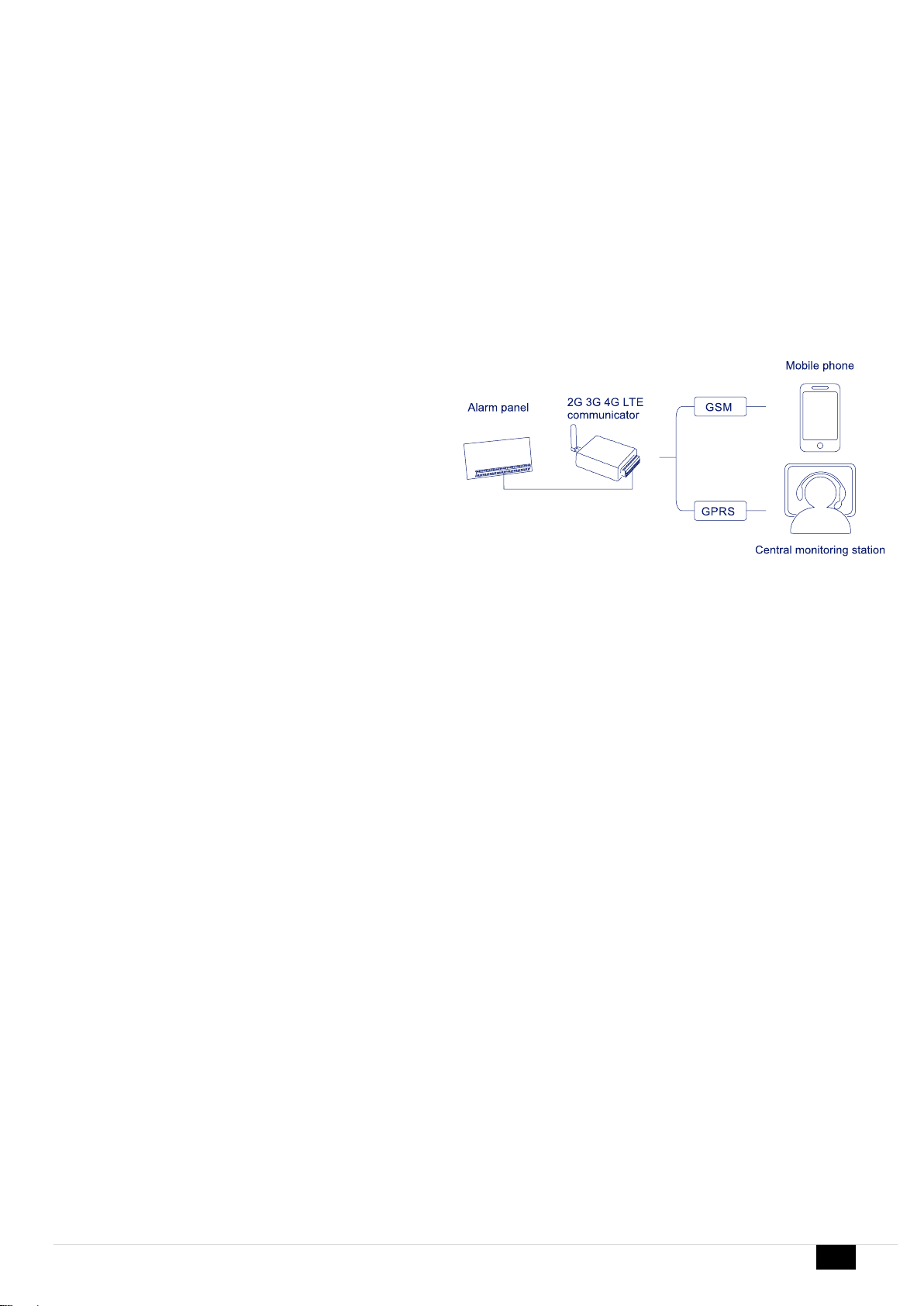
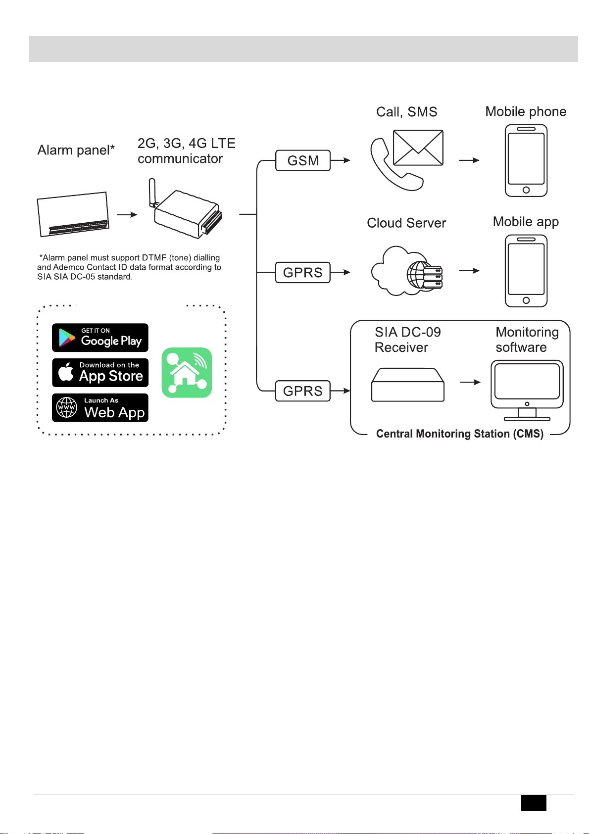
1GENERAL INFORMATION...............................................................................................................................................................5
1.1 Specifications..................................................................................................................................................................................................6
1.2 Used definitions and terms..............................................................................................................................................................................7
1.3 Package content.............................................................................................................................................................................................8
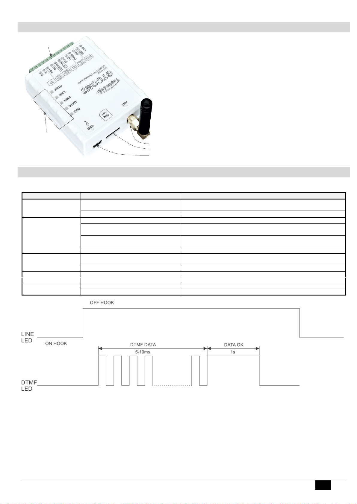
1.4 General view of the module.............................................................................................................................................................................9
1.5 Meaning of LEDs and contacts........................................................................................................................................................................9
2QUICK START................................................................................................................................................................................10
2.1 Requirements of the Security Control Panel..................................................................................................................................................10
2.2 Requirements for SIM card ...........................................................................................................................................................................10
2.3 Preparation...................................................................................................................................................................................................11
2.4 Fastening......................................................................................................................................................................................................11
2.5 Configuration methods..................................................................................................................................................................................12
2.6 SERA2 software............................................................................................................................................................................................12
2.7 SERA Cloud Service: Remote Connection to the Module via Internet Using the SERA2/SERANOVA...........................................................12
2.8 SERANOVA (Android/iOS/Web) app.............................................................................................................................................................14
3WIRING & INSTALLATION ............................................................................................................................................................16
3.1 Communicator wiring methods......................................................................................................................................................................16
3.2 Programming the Primary PSTN Alarm Panel...............................................................................................................................................17
3.3 Remote ARM/DISARM of Primary Alarm Panel Using GTCOM2 with SERANOVA App................................................................................17
3.3.1 GTCOM2 and primary alarm panel synchronization [by Panel’s EVENTS] ...............................................................................................18
3.3.2 GTCOM2 and primary alarm panel synchronization [by Panel’s PGM] .....................................................................................................19
3.4 How to Test Synchronization between GTCOM2 and the Primary Alarm Panel.............................................................................................20
3.5 GTCOM2 Communicator - Converter for Ademco Contact ID codes into SMS text .......................................................................................21
4SYSTEM ACCESS: CODES, PASSWORDS, AND PERMISSIONS..............................................................................................23
4.1 Default Codes/Passwords and Explanations.................................................................................................................................................23
4.2 User codes for access control via keypad and SERANOVA app ...................................................................................................................24
4.3 Access control. Arming/Disarming methods ..................................................................................................................................................25
4.4 Users & Access Control programming details................................................................................................................................................26
4.5 Wiring of Wiegand Keypad, RFID Card Reader, and iButton Probe...............................................................................................................28
4.6 Programming iButton, RFID, Phone numbers to the memory of the module..................................................................................................28
5OUTPUTS .......................................................................................................................................................................................30
5.1 Schematic and Wiring of Outputs..................................................................................................................................................................30
5.2 Output Programming.....................................................................................................................................................................................30
6INPUTS ...........................................................................................................................................................................................31
7SENSORS & AUTOMATION ..........................................................................................................................................................32
7.1 Humidity sensors AM2302/DHT22/AM2305/AM2306/AM2320/AM2321........................................................................................................32
7.2 Analog Inputs 0-10V Setup ...........................................................................................................................................................................33
7.3 Temperature sensors Dallas 1-wire DS18b20 installation & recommendations..............................................................................................33
7.4 How to change temperature scale from Celsius to Fahrenheit.......................................................................................................................34
7.5 Example of Thermostat Control for Heating and Cooling...............................................................................................................................35
7.6 How to test the sensors.................................................................................................................................................................................35
8Programming with SERA2 configuration software.....................................................................................................................37
8.1 General system options programming...........................................................................................................................................................38
8.2 Real-time clock Time Zone and Synchronization...........................................................................................................................................39
8.3 GSM Communicator Programming................................................................................................................................................................40
8.3.1 Event Notifications via SMS & DIAL .........................................................................................................................................................40
8.3.1 Custom SMS Text....................................................................................................................................................................................41
8.3.2 Network/SIM Card/GPRS/LTE programming............................................................................................................................................41
8.3.3 Central Monitoring Station details programming. Reporting to the Central Monitoring Station (CMS)........................................................42
8.4 Inputs/Zones programming ...........................................................................................................................................................................43
8.1 Outputs PGM programming...........................................................................................................................................................................44
8.2 Sensors Programming & Automation/Sensors/Analog Inputs Programming..................................................................................................45
8.1 Event List (Events)........................................................................................................................................................................................46
8.2 Events Log....................................................................................................................................................................................................46
8.3 Real-Time Testing & Monitoring of Hardware................................................................................................................................................47
8.3.1 RT Testing & Monitoring Security Alarm Panel/ Access............................................................................................................................48
8.3.2 Real-time Testing & Monitoring > Event Monitoring..................................................................................................................................48
8.4 SERA2 Remote Configuration, Firmware Updates, Monitoring, and Logging.................................................................................................49
9SMS Commands for remote control and configuration .............................................................................................................51
9.1 The table of installers SMS commands .........................................................................................................................................................52
9.2 The table of users SMS commands...............................................................................................................................................................56
10 System Info of device and Firmware Updates ............................................................................................................................57
11 Warranty Terms and Conditions ..................................................................................................................................................58

GTCOM2 User manual v.2024-01-04 5 | EN
1 GENERAL INFORMATION
Figure 1 Structural schematic with usage
•The GTCOM2 module sends GSM-based SMS alerts about security system events to users.
•Converts Contact ID DTMF data from any security panel's PSTN communicator into SMS; transmits to central monitoring stations (CMS) using
the SIA DC-09 IP protocol, ensuring compatibility with SIA DC-09 receivers.
•Displays the security panel status on the SERANOVA mobile app.
•Synchronizes statuses between the GTCOM2 and the primary alarm panel for control and monitoring, which are accessible through both the
app and keyboard.
•In the event of an alarm or other occurrence, it sends sequential SMS messages (SMS1, SMS2... SMSn) and calls (DIAL1, DIAL2... DIALn) to
each of the 8 users.
SERANOVA

GTCOM2 User manual v.2024-01-04 6 | EN
1.1 Specifications
Parameters of built-in GSM module:
Quad-band (850/900/1800/1900 MHz)
Optional 3G ,4G LTE bands
Sending of SMS messages
Receiving of calls and dialing
Data download/upload via GPRS network
IN1, IN2 inputs:
•Burglary alarm zones. Input type
NC/NO/EOL/EOL+TAMPER 2.2K + 2.2K;
•10K pull up resistor;
•Analog input 0-10V;
•Response time;
•Time of repeatable Alarm/Restore;
•Commutation of selected output;
Inputs/outputs I/O1, I/O2:
Programmable output;
•Open Drain 24V/1A ,
•Short Circuit Protection
•Overvoltage Protection (Active Clamp)
•Overcurrent Protection
Programmable Input:
•NC, NO or EOL=5.6kΩ (settable)
Digital 1-Wire interface 1W:
800 iButton users - DS1990A,
up to 32 temperature sensors DS18b20
Aosong 1-Wire bus Humidity Sensor AM2302
DHT22 AM2305 AM2306 AM2320 AM2321;
Protocol to Central monitoring station (CMS):
ARC –Alarm receiving center
SIA IP DC-09 protocol:
•Standards supported:
oDC-09-2007,
oDC-09-2012,
oDC-09-2013,
oDC-09-2021
•Backup channel: Yes
•UDP/TCP: Yes
•AES128 bit encryption: Yes
•Ping Supervision Messages: Yes
•Time Stamp synchronization: Yes
Wiegand interface D0,D1 (DATA0/ DATA1):
•Wiegand Keypad / RFID reader;
•Wiegand Keypad / RFID reader:
•26-bit,34bit Wiegand RFID card format
•4-bit, 6-bit, 8-bit Keypad PIN/CODE format
•The total length of the bus from 10 to 100m.
Module control:
ARM/DISARM of the security system via:
•Free SERANOVA app (Android, IOS, web)
•SMS message 800 users
•short call DIAL 800 users
•Maxim-Dallas iButton key (iButton DS1990A
–64 Bit ID)) 800 users.
•Wiegand keypad code or RFID keycard or
key fob 800 users
Buffer for unsent events:
Nonvolatile flash events log 3072 events
5V power source output:
•Voltage 5V
•Current limit 100mA
Power supply voltage:
•DC 10-16 V / 200mA max
•Max. Allowed ripple voltage 100mV.
Consumption current:
In standby mode less than 50 mA.
In dialing or SMS/GPRS sending mode
less than 200 mA.
Environmental parameters:
Storage temperature range
from -40 to +85 oC / -40 to 185 oF
Operational temperature range
from -30 to +75 oC / from -22 to 167 oF
Max relative humidity:
0-90% RH @ 0… +40°C (0-90% RH @
+32… +104°F) (non-condensing)
Package weight 90g
Module weight: 43g
Overall dimensions of the module:
73x62x26mm

GTCOM2 User manual v.2024-01-04 7 | EN
1.2 Used definitions and terms
Term
Description
Alarm Log
Records of system events
Arming/Disarming
The process to activate or deactivate the system's security.
Authorized user
A person with a mobile number registered in the GTCOM2 module. Multiple users with equal rights can be added.
Backup battery
The secondary power source of the system. In case of a main power failure, the backup battery will take over.
Bell squawk
Siren signals indicating arming (2 short beeps) and disarming (1 long beep). Default is off.
Bypass/Activate Zone
Allows disabling a compromised zone for arming. The zone is ignored if breached while armed and stays bypassed till
disarmed.
Caller ID
Identifying the caller's phone number.
COM
Negative power supply terminal.
Configuration
Setting system parameters such as phone numbers, input names, etc.
CMS
Central monitoring station
DIAL
The system makes a call to the number specified.
Diagnostic Tool
When using Configuration tool software, you may monitor system inputs/ outputs, view changes of peripheral devices,
instantly configure necessary options, for example, enabling/disabling PGM outputs, etc.
Entry Delay
Countdown initiated upon violation of a Delay-type zone. If disarmed before expiry, no alarm triggers.
EOL
(End of line resistor) input type with resistor.
Event
The information that the user receives.
Event Log
Recorded system events. Logs actions, configurations, and info messages.
Exit Delay
Time after arming for users to leave the secured area.
Fault
An issue preventing normal system operations. The system can diagnose and notify of faults via SMS.
iButton key
A unique 64-bit ID code containing chip enclosed in a stainless-steel tab usually implemented in a small plastic holder.
The module supports up to 800 iButton keys each holding a unique identity code (ID), which is used for system arming
and disarming.
Installer
a person provided with INST (installer's) password
Master/User Code
Allows to carry out system arming/ disarming as well as minor system configuration and control
Normally closed (NC)
It is a switch that passes current until actuated.
Normally open (NO)
It is a switch that must be actuated to pass current.
Periodic Test Event
Regular system test event with date, status, signal strength etc.
Pull-up resistor
Is that it weakly "pulls" the voltage of the wire it is connected to towards +V (or whatever voltage represents a logic
"high").
PGM output
A PGM output is a programmable output that toggles to its set up state when a specific event has occurred in the system
or if the user has initiated the PGM output state change manually.
Ping period
Sets period of time defining how often the module sends ping data packet to the server.
Service messages
ARM/DISARM, test, resetting of the system.
SSR
Solid State Relay
SMS forward
System can re-sent all incoming SMS messages to the specified users. It is useful if the GSM operator of the inserted
SIM card sends some useful information (SIM card validation or payment account status and etc.) or it is necessary to
monitor all incoming SMS messages by specified user.
User
It is a person being aware USER password.
Zone
Detection devices such as motion detectors and door contacts are connected to the alarm system’s zone terminals.
Zone state/status
Indicates a zone's condition: violated or restored.
+V
Positive power supply terminal.

GTCOM2 User manual v.2024-01-04 8 | EN
1.3 Package content
Table 1 Standard package content
GTCOM2 module –1 pcs
Shipping Package - 1 pcs
Package content may be vary without a notice. Ask the seller before buying!
Table 2 Additional, under request package content
Cellular Antenna 2.5 dBi L-Type
SMA Connector
4G LTE Antenna 3dBi SMA male
Adhesive Mount 2m Cable
4G LTE Antenna 7dBi SMA male
Magnetic 2m Cable
4G LTE Antena 5dBi SMA male
Magnetic 2m Cable
Waterproof Temperature Sensor
DS18B20 cable 1m
Temperature sensor DS18B20
Digital Temperature/Humidity
Sensor Am2305
Humidity sensor AM2320
iButton DS1990A-F5+ key
iButton probe with LED indicator
Mini USB cable
Wiegand keypad & RFID reader

GTCOM2 User manual v.2024-01-04 9 | EN
1.4 General view of the module
1. LED Indication: See Table 3 for the meaning of LEDs.
2. Mini USB Connector: Used for module configuration and firmware updates.
3. SIM Card Holder: Push-push type for Nano SIM.
4. ANT GSM Antenna Connector.
5. Terminal Block: For power supply and input/output connections.
1.5 Meaning of LEDs and contacts
Table 3 Meaning of LEDs
Name
Indication variations
Meaning
WDG (green) built-in
LED
Watchdog heart beat blinking, remains lit for
50ms, and turns off after 1000ms.
The module is functioning.
Off
The module is out of order or no voltage
REG (yellow) built-in
LED
Lights continuously
Modem has been registered to the network
Flashes, remains lit for 50ms, turns off for
300ms
Modem is being registered to the GSM network.
Blinking fast, remains lit for 50ms turns off
for 50ms
PIN code of SIM card error. PIN code request should be removed
Off
Modem failed to register to the network.
DATA (red) built-in LED
Lights continuously
The memory of the module contains unsent reports to the user or to the
server.
Off
All data has been sent.
LINE (blue)
Lights continuously
The security control panel has picked up a handset Off-hook
OFF
The security control panel has not picked up a handset On-hook
DTMF
Blinking 5-10ms
DTMF tones are receiving from the control panel
Blinking 1s
DATA OK. Data received correctly.
Figure 2 Meaning of LINE and DTMF LEDs
LINE (blue) LED lights continuously, when central panel OFF HOOK DTMF LED is blinking (5-10ms). When DTMF LED lights for 1s, data received
correctly.
1
2
3
4
5

GTCOM2 User manual v.2024-01-04 10 | EN
Table 4 Terminal block. Contacts.
Name
Optional functions and Description
DC+
DC
10-16V
Max
0.2A
COM
Common terminal (negative)
TIP
Terminal to connect with security control panel TIP terminal
RING
Terminal to connect with security control panel RING terminal
I/O1-I/O2
Programmable functions
Digital input (zone) NC/NO/EOL/EOL+Tamper [1]
Open drain output 16V/1A
Analog voltage input 0-16V
IN1/D0 …
IN2/D1
Programmable functions
Input/Zone with pull up resistor 10K to the VD+. Used for gate position or security
sensors
Can be configured NC/NO/EOL/EOL+Tamper
Wiegand interface. Inputs D0 and D1 used for Wiegand RFID reader, keypad
1W
Programmable functions
Digital output (Max 3.3V)
Digital input (Max 3.3V)
Dallas 1-Wire bus. For iButton DS1990A and temperature sensors DS18B20
Aosong 1-Wire bus. Humidity Sensor AM2302, DHT22, AM2305, AM2306
Max available voltage
+3,3V
Max available current
10mA
+5V
Power supply for external temperature, humidity sensors
Max available voltage
+5V
Max available current
100mA
A
RS485 bus A contact
B
RS485 bus B contact
[1] If the zone used for security system purpose 5.1k pull-up resistor should be connected
2 QUICK START
•Settings can be saved to file and quickly written to other communicators.
•Two access levels for configuring the device for CMS administrator and for installer.
•Remote configuration and firmware updates.
2.1 Requirements of the Security Control Panel
The security control panel should meet the following requirements:
•Support the Ademco Contact ID protocol in accordance with the SIA DC-05 standard.
•Support dialing in DTMF tones.
•Support the transfer of Contact ID data in DTMF tones.
•It is recommended that the control panel supports automatic Contact ID codes.
2.2 Requirements for SIM card
•Any SIM card could be used. The GTCOM2 module is not locked to a specific GSM network. This means users can use a SIM card from any
GSM service provider that offers SMS and calling capabilities.
•For controlling the module via a short call, the SIM card should have a Caller ID option, which is typically available. If your card cannot identify a
caller, please contact your GSM service provider or use another SIM card.
•To insert the SIM card into the holder, ensure the card's circuitry faces downward and the card's key (cut angle) faces upward. The card holder
is of the "Push-Push" type, meaning the card is secured after one push and released after a second push.
•Avoid forcing the SIM card into its holder to prevent damage to the SIM card holder.
Do not insert the SIM card forcefully, as this may damage the SIM card holder.
Data usage can be enabled or disabled, but to use the remote cloud service, data must be enabled.

GTCOM2 User manual v.2024-01-04 11 | EN
2.3 Preparation
Before you begin, ensure that you have the necessary items:
•A USB cable (Mini-B type) for configuration.
•At least a 4-wire cable for connecting the communicator to the control panel.
•A flat-head screwdriver, 2.5mm in size.
•A cellular antenna with sufficient gain, if network coverage in the area is poor.
•An activated Nano-SIM card (with the PIN code request disabled).
•The specific installation manual for your security control panel.
2.4 Fastening
Mounting on DIN rail
Fasten the base of the case in the desired place using screws
Figure 3 remove the top lid
Figure 4 Remove the PCB board
Figure 5 Fasten DIN rail adapters to the base of the case
Figure 6 fasten the base of the case

GTCOM2 User manual v.2024-01-04 12 | EN
2.5 Configuration methods
It is possible to configure device in following methods:
•SERA2 software via USB (recommended)
•SERA2 remote connection over internet Cloud service
•SERANOVA app
•SMS text commands. For more details, see:
2.6 SERA2 software
2.6.1.1 SERA2 Software Installation:
•Visit http://topkodas.lt and download the SERA2 software.
•Locate and open the folder containing the SERA2 software installation files. Click on "SERA2 setup.exe."
•If the installation directory is correct, click [Next]. To choose a different directory, click [Change], specify the desired installation directory, and
then click [Next].
•Verify the entered information and click [Install].
•Once the SERA2 software installation is successful, click [Finish].
2.6.1.2 Configuration using SERA2 software
With SERA2 software you can change the controller’s settings (if default settings are not enough)
•Download and install and open free SERA2 configuration & Diagnostic software: https://www.topkodas.lt/Downloads/SERA2_Setup.exe
•Connect the controller to a computer using a mini-USB cable.
•The program will automatically recognize the connected device and will automatically open the controller configuration window.
•[Menu > Read] will readconfiguration of device and show current settings of device.
•[Menu > Write] will save the settings made in the program to the device.
•[Menu > File > Save] will save the settings into a configuration file. You can upload
the saved settings to other Devices later. This allows to quickly configure multiple
devices with the same settings.
•[Menu > File > Open] will allow to choose a configuration file and open saved settings.
•If you want to revert to default settings, go to Update in the command line and update FW. Or press [Menu->File->Restore Default]
2.7 SERA Cloud Service: Remote Connection to the Module via Internet Using the SERA2/SERANOVA
GSM Communication > SERA Cloud Service
The TCP/ IP Remote Control window let you set basic TCP IP remote control
settings and enable or disable remote communication.
SERA Could Service –is used for remote connection to device via internet using SERA2 or SERANOVA app.
Imortant! If there is no data plan on your SIM card. [SERA Cloud service] must be deactivated. Using SERA2 or SMS command:
INST000000˽010˽0 Otherwise the module will stop working due to a lost data connection.
Remote Connection Capabilities:
•Access to the SERANOVA app (Android, iOS, WEB) or SERA2 windows software.
•Remotely configure system parameters, monitor hardware status, input voltage, temperature sensors, and GSM network levels.
•Update the module's firmware and read the event log.
What can be done remotely connecting to a module over the internet?
•Use SERANOVA app (Android, IOS, WEB)
•Use SERA2 windows software remotely via internet.
oConfigure system parameters
oMonitoring of hardware system status, input voltage, including temperature sensors, GSM network parameter levels.
oUpdate the module's firmware.
oTo read event log
How it Works:
•Connection Protocol: A GPRS/LTE-backed TCP/IP protocol.
•Connecting Platform: Connects through GPRS/LTE to the SERA cloud server using the module's unique IMEI (UID).
•Communication Pathways:
oGTCOM2 (device) ↔[SERA Cloud Service] ↔SERA2 (configuration software) for system setup and management.
oCTCOM2 ↔[SERA Cloud Service] ↔SERANOVA app (compatible across Android, iOS, and standard web browsers like Firefox,
Chrome, etc.)
•SERA Cloud Server's Role: Creates a communication tunnel between GTCOM2 and SERA2/SERANOVA app, facilitating two-way
communication through the TCP protocol.
Note: Ensure GPRS service is active on the module's SIM card. If it's not automatically activated, contact your GSM provider. A data
plan is recommended, with the module consuming 10-50MB monthly on average.
SERA2 software is intended for GTCOM2 configuration locally via USB port or remotely via ‘SERA Cloud Service’ internet GPRS/LTE
2G/3G/4G network. This software simplifies system configuration process. SERA2 software is free, which you can download from our
website: https://www.topkodas.lt/Downloads/SERA2_Setup.exe

GTCOM2 User manual v.2024-01-04 13 | EN
GPRS/LTE Mobile Data Requirements:
•Any active SIM card can be used. The module is not locked to any
specific network and can work with any SIM card that supports SMS
and calls.
•Employ a SIM card with a data plan enabled.
•Estimated data consumption: Between 10 to 50MB monthly.
Setting Up Remote Control:
•Install the SERA2 software.
•Navigate to 'SERA2>GSM Communications>Network/SIM Card' tab to
configure APN, login, and password (details provided by your network
provider).
•Go to 'SERA2>GSM Communications>SERA Cloud Service' tab and
activate [SERA Cloud Service] with default settings.
•Press [Write] to save the configuration.
Make sure the correct APN is set. Using the wrong APN may result in data and VoLTE not working. Consult your network provider for
the correct APN details.
Enable
Activate/deactivate remote internet control ‘SERA Cloud service’.
IP or Domain
Set to either IP (xxx.xxx.xxx) or domain (default: cloud.topkodas.lt).
Remote Port
The default port is 10000; make sure the firewall is not blocking this port.
App Key
Server encryption key. Default value set to 123456.
Steps to connect remotely to device via internet using [SERA Could
Service]:
•Insert the SIM card into the module.
•Ways to get device IMEI (UID):
oFirst call to module. The caller will receive a greeting SMS
with the IMEI of the module.
oBy sending an SMS command: INST000000˽100˽1
oRun SERA2 and connect device to USB. Go to: SERA2 >
System Options > System Info.
•Check “SERA Cloud Service (default)” checkbox.
•To connect, use the module's UID (IMEI) and AppKey
(default:123456)
•Use the same AppKey (default:123456) in the module and in
SERA2 or SERANOVA for remote connection.
•Click the [Connect] button. Wait for a 'TCP connected' notification
to appear.

GTCOM2 User manual v.2024-01-04 14 | EN
If needed, APN/Password/Login/IP/Domain/ Port /PING time /KEY can be set by SMS commands
GPRS network settings
INST000000˽008˽APN#LOGIN#PSW#
•008: Command code
•APN: Access Point Name (31 char. max).
•LOGIN: User login (31 char. max).
•PSW: Password (31 char. max).
Remote control of the module over the Internet.
INST000000˽009˽ADDR#PORT#PING#KEY#
•009: Command code.
•ADDR: IP address (format xxx.xxx.xxx.xxx) or domain (up to 47 characters).
•PORT: TCP port number (1 to 65535).
•PING: Ping time =600
•KEY: App Key (Default is 123456).
SERA2 software can remember all IMEI that was entered in the past. If needed to clean the list UID/IMEI, press “Clear History”.
2.8 SERANOVA (Android/iOS/Web) app
With the SERANOVA app, users will be able to control gates and other devices remotely, as well as administer users, view system status and push
notifications, and view a log of all events.
To use the SERANOVA app or the SERA2 remote connection. The [SERA cloud service] needs to be activated by using the SERA2 or SMS
command e.g. INST000000˽010˽1. By default [SERA cloud service] service is activated.
Imortant! If there is no data plan on your SIM card. [SERA Cloud service] must be deactivated. Using SERA2 or SMS command:
INST000000˽010˽0 Otherwise the module will stop working due to a lost data connection.
SMS command to set APN DATA/GPRS/LTE network settings. Some networks require exact APN name to be entered, otherwise data connection will
not work. Network APN can be configured using SERA2 via USB or following SMS command:
INST000000˽008˽APN#LOGIN#PSW# where: APN=the name of network APN default=”internet”,
LOGIN=login leave empty if not used; PSW =password leave empty if not used.
e.g.INST000000˽008˽internet### where APN=’internet’; no LOGIN; no PSW
1. Install the app. Scan a QR code with your phone or start it on the web.
Free WEB SERANOVA app https://seranova.eu/login
SERANOVA website https://www.topkodas.lt/SERANOVA-app/
SERANOVA
SERANOVA app for iPhone iOS: https://apps.apple.com/app/SERANOVA-smart-home/id1596644632?platform=iphone
Android SERANOVA app: https://play.google.com/store/apps/details?id=com.SERANOVA.cloud&hl=en&gl=US
2. Register or sign in to your account.
3. How Get IMEI: To add a system, the device's IMEI is required. Obtain the IMEI by:
•Making the initial call to the device. The first caller becomes the owner and administrator and receives an SMS with the IMEI from GTCOM2.
Copy the IMEI, which serves as the module's UID and allows connection to the free SERANOVA app.
•Sending an IMEI request SMS command INST000000˽100˽1 to the controller's SIM card number. The sender will receive an SMS response
with complete device information, including the IMEI.

GTCOM2 User manual v.2024-01-04 15 | EN
•Reading the IMEI via USB using the SERA2 configuration program from System Options > System Info
4. Add new system to the app
•Enter the IMEI (UID) you copied from the SMS or SERA2 system information
•Enter App Key (default: 123456).
•Enter the User Access Code (default: 123456). Without a user access code, the system cannot operate. This code serves as both the user
ID and password within the system. Each user must have a unique code, which is located in the user table. The system administrator creates
and provides these codes to each user.
•Phone number of system
•Enter system name.
•Press [SAVE].
5. How to add a new user
•New users must download the SERANOVA app. Create an account, login with his email and password
•System owner or administrator goes to SERANOVA> Menu> Users> [Add new User]
•To enable a user to log in to the system, the owner must enter the user's email and user code (with which the system will be operated. This
is the user ID and password). This is enter the user email that was used to create the SERANOVA account. Enter User code (Default 1234),
Phone number, Set Output for control, User privileges: admin or user
1.Install SERANOVA app
2.Create account
3.Log In
4. The first person to call the
GTCOM2 SIM card number
becomes the owner and
administrator.
5. GTCOM2 sends a message with
the IMEI
6. Enter the IMEI and App Key
(Default 123456), Enter User
access code (Default 123456)
7. The system is now manageable
8. Go To SERANOVA> Menu>
Outputs. Edit settings
9. Select pulse or level
10. Go to SERANOVA> Menu>
Users: Press [Add New User]
Owner or administrator can add
other users or administrators
11. Enter the email used to create
the SERANOVA account, along
with your unique user code. Please
note, system control is not possible
without this user code.
How to add additional system (unlimited number) to SERANOVA app:
Go to SYSTEMS, Choose Add new system and enter the controller Unique ID (IMEI) number. IMPORTANT: When adding the controller to SERANOVA
app: 1. The [Sera Cloud Service] must be turned on.
2. The power supply must be connected
3. Device must be registered in to network and have mobile data plan
4. Set valid APN of the network. Ask your network provider for valid APN. (default: ‘internet’)
More help how to setup device and app could be found here:
QUICK START SERANOVA app
https://youtu.be/Benf6xKcnjM
Enter a valid email address of a user who already has a SERANOVA account. The system will be automatically added to the user's account.
If the user is added without a validSERANOVA account email. The usercan create aSERANOVA account later and addthe system manually.

GTCOM2 User manual v.2024-01-04 16 | EN
3 WIRING & INSTALLATION
Preparation procedure of the module GTCOM2.
•Screw on the GSM antenna.
•Insert the SIM card in the SIM card holder. (Ensure that PIN request function is disabled. Ensure that mobile internet service (mobile data) is
enabled if mobile app or IP connection with CMS will be used)
•Connect power supply.
•Wait for the controller to register to the GSM network
•Connect the module to the computer via mini-USB cable.
•Connect the module to the primary alarm panel.
3.1 Communicator wiring methods
•The GTCOM2 module enhances third-party security systems with PSTN communicators by providing GSM/LTE/IP connectivity.
•It uses a RING/TIP PSTN interface to connect to security panels, converting Ademco Contact ID data into SMS for up to 8 users, and reports to
the CMS using the SIA IP DC-09 protocol.
•With two digital inputs, the GTCOM2 monitors the security panel's ARM/DISARM/STAY states and other alarms, immediately sending SMS and
calls upon siren activation and reporting to the CMS.
•With two outputs, GTCOM2 controls ARM/DISARM states and remote gate access, linking to keyswitch-configured zones for partition control.
•The module's status synchronizes with the control panel, shifting between ARM and DISARM as required. It also displays the system status on
the SERANOVA mobile app.
The GTCOM2 can be connected to a security panel in two ways:
1. Connection solely to the PSTN communicator for receiving all events from the security panel, and relaying these events as readable SMS to
user mobiles, as push notifications to the Android/iOS SERANOVA App, and to the Central Monitoring Station receiver via the internet using
the SIA DC-09 protocol.
2. Connection to the PSTN communicator with added remote ARM/DISARM control of the alarm panel through a keyswitch zone.
Figure 10Communicator wiring diagram
Figure 11 ARM the panel via keyswitch zone
Figure 7 Insert the SIM card
Figure 8 Screw the GSM antenna
Figure 9 connect the module to the computer

GTCOM2 User manual v.2024-01-04 17 | EN
3.2 Programming the Primary PSTN Alarm Panel
The configuration of the panel's PSTN communicator should be similar to event transmission to the monitoring station receiver using the CONTACT ID
DTMF protocol. The module can work with any central panel that has a PSTN communicator and adheres to the Ademco Contact ID data format as per
the SIA DC-05 standard. Additionally, the central panel must support phone number dialing using DTMF tones. (Note: Pulse dialing is not supported by
the GTCOM2).
Configuring the Panel's PSTN Communicator for CONTACT ID DTMF Protocol:
•Ensure the central panel supports the Ademco Contact ID format (SIA DC-05) and DTMF tone dialing (Note: Pulse dialing is incompatible with
GTCOM2).
•Activate the panel’s PSTN dialer
•Set a 4-digit communicator account (e.g., “1234”).
•Input the monitoring station receiver’s phone number (GTCOM2 responds to any number over 2 digits). **
•Set communication dialing options to [DTMF Dialing].
•Set Communications protocol to [DTMF Contact ID].
•If available, activate [Contact ID Automatic Reporting Codes].
•Enable relevant PSTN communication events (Open/Close/Alarm/Restore/Maintenance/Test).
Panel’s Settings for Two-Way ARM/DISARM Synchronization***: [APP/Call/SMS/iButton] <->GTCOM<->PANEL<-> [Panel Keyboard]
•Set Panel PGM to monitoring ARM status in level (steady) Mode
oActivation event: [ ARM Area1]
oDeactivation Event: [ DISARM Area1]
oMode: [Steady]
oNO/NC depending of GTCOM22 input keyswitch settings.
oIn our example set to [NO]
•Set Panel Keyswitch Zone to Momentary (Pulse) Mode) to receive ARM/DISARM signals from the GTCOM2 [System Armed state]
Output PGM.
oZone Type: [Keyswitch Momentary] (Pulse)
oArea Assignment: [Area 1] (Set AREA you want to control)
oKeyswitch Action: [ARM/DISARM]
*The communicator supports the SIA Ademco CONTACT ID data package protocol (as per the SIA DC-05 standard).
**The telephone number and data transfer format are DTMF (tone).
*** Two-way ARM/DISARM synchronization allows the USER to control the panel via the panel’s keyboard as well as remotely from the GTCOM2
APP/WEB/SMS/iButton/RFID/Call. This ensures that the GTCOM2 APP displays the same system status as the security panel's keyboard.
GTCOM2 do not accept pulse dialing from PSTN communicator
3.3 Remote ARM/DISARM of Primary Alarm Panel Using GTCOM2 with SERANOVA App
GTCOM2 & Primary Alarm Panel Synchronization
Synchronize alarm panel status with the GTCOM2 SERANOVA app
in two ways:
1. Through primary panel events: GTCOM2 updates its
SERANOVA app status with each Open/Close event from
the main panel.
2. Via the panel's PGM output ARM state: a faster method,
but it requires an extra wire to the PGM for status
monitoring.
Open/Close synchronization allows panel control via keypad or
remotely through the GTCOM2 SERANOVA app /web/SMS/call,
ensuring the app reflects the panel's actual status.
It is possible:
- To control primary alarm panel from SERANOVA app and see the panel status
- To control primary alarm panel from keypad and see the same status in SERANOVA app

GTCOM2 User manual v.2024-01-04 18 | EN
3.3.1 GTCOM2 and primary alarm panel synchronization [by Panel’s EVENTS]
Wiring:
•TIP/RING
•GTCOM PGM -> Panel Keyswitch (pulse mode)
Set system status synchronization mode [By Panel Events]:
•Go to SERA2> System Options> General System Options
•Set App ARM/DISARM Synchr mode to [By Panel Events]
Set module PGM action on ARM/DISARM command from APP/CALL/SMS/iButon/RFID
•Out Definition: [Activate by ARM/DISARM Command]
•No: [1] (this is partition number)
•Mode: [Pulse]
•Timer: [2s] (this is PGM pulse time on ARM/DISARM command)
Figure 12SERA2> Outputs (PGM)
A
+5V
TIP
1W
IN /D2 1
B
COM
DC+
RING
ANT
PWR
LINE
DATA
DC10- V16
Max 0.2A
Nano
SIM
REG
IN1/D0
IO1
IO2
1-WIRE
Sensors
iButton
To Panel’s
PSTN
connector
USB
Inputs
WIEGAND
Reader
Inputs/
Outputs RS485
BUS
DTMF
GSM PSTN/ Communicator
ARM/DISARM via keyswitch Zone
ARM/DISARM partition 2 via keyswitch

GTCOM2 User manual v.2024-01-04 19 | EN
3.3.2 GTCOM2 and primary alarm panel synchronization [by Panel’s PGM]
Wiring:
•TIP/RING
•GTCOM PGM -> Panel Keyswitch zone (Pulse mode)
•GTCOM Keyswitch <- Panel PGM (Level Mode)
Set system status synchronization mode [By Panel PGM]:
•Go to SERA2> System Options> General System Options
•Set App ARM/DISARM Synchr. mode to [By Panel PGM]
Set GTCOM2 keyswitch zone
•Go to SERA2> Inputs> Burglar Alarm Zones and set:
•Keyswitch Zone Mode: [Level] (Steady)
•Definition: [keyswitch ARM/DISARM]
•Type: [NC]
•Press [Write]
Figure 13 SERA2> Inputs/ Burglar Alarm Zones
Set module PGM action on ARM/DISARM command from APP/CALL/SMS/iButon/RFID
•Out Definition: [Activate by ARM/DISARM Command]
•No: [1] (this is partition number)
•Mode: [Pulse]
•Timer: [2s] (this is PGM pulse time on ARM/DISARM command)
Figure 14 SERA2> Outputs (PGM)
A
+5V
TIP
1W
IN /D2 1
B
COM
DC+
RING
ANT
PWR
LINE
DATA
DC10- V16
Max 0.2A
Nano
SIM
REG
IN1/D0
IO1
IO2
1-WIRE
Sensors
iButton
To Panel’s
PSTN
connector
USB
Inputs
WIEGAND
Reader
Inputs/
Outputs RS485
BUS
DTMF
GSM PSTN/ Communicator
PGM1 System state Set a Zone as keyswitch

GTCOM2 User manual v.2024-01-04 20 | EN
3.4 How to Test Synchronization between GTCOM2 and the Primary Alarm Panel
STEP by STEP:
•Navigate to SERA2 > RT Testing & Monitoring > Hardware.
•Click the [Start Monitoring] button.
•Press [I/O1 On/Off] button.
•Observe the change in Inputs (ADC values); they should switch from 1 to 0 or 0 to 1.
•The status of the primary panel should change accordingly.
Figure 15 SERA2> RT Testing & Monitoring> Hardware
•Go to SERA2> RT Testing & Monitoring> Security Alarm Panel/ Access
•The status of GTCOM2 module should change
Figure 16 SERA2> RT Testing & Monitoring> Security Alarm Panel/ Access
You will see the same process on your smartphone in the mobile app as well.
Other manuals for GTCOM2
2
Table of contents