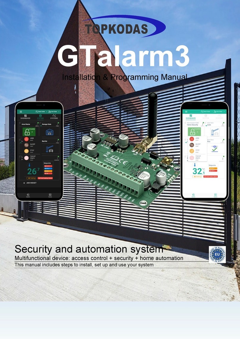
Topkodas GTalarm2 Installation and operating instructions

GTalarm2
Application Note: Security, Alarm System
Monitoring, alarm, control.
This manual includes steps to install, set up and use your system.

Application Note: Security, Alarm System www.topkodas.lt 2 | EN
GTalarm2 is a user-friendly security system that monitors your site’s
detectors and alarms. Fully programmable, the module GTalarm2
allows you to control hundreds of critical security functions from one
menu-driven interface.
The system consists of a central control unit, an operating panel, and
up to 32 protection points. While monitoring protection points 24 hours
a day the controller itself is electronically monitored by trained central
monitoring station personnel. If a hazard or security breach occurs, the
appropriate authorities (police, fire) are alerted.
All functions are accessed through the system operating panels or
through card/key readers.
Attractive, easy-to-use operating panel.
Control of up to 32 protection points from one central location.
Manual activation or deactivation of any function.
Ability to on in either the AWAY or STAY mode.
Ability to bypass points for maintenance or service.
Capacity of up to 800 individual operating panel users, each
having various security privileges.
Capacity of up to 800 individual card/key reader users, each
having various levels of access.
Control and recording of employee access to workplace
areas.
Recording of security-related activities.
Ability to send messages to up to 8 users.
The GTalarm2 module –the brains of your security system –is a
powerful microcomputer that manages every function of your security
system. All information about your site’s security is stored in this unit or
in the server.
Features of the module GTalarm2
Communication via SIA IP DC09 protocol
6 on-board zones. Input EOL/NO/NC and Tamper
Tamper supervision available, ensuring product is always secure
Built-in access control features
Automatic Daylight Savings Time feature
I/O1 and I/O2 can be used as a 2-wire smoke input
4 Analog inputs (pull up 5.1K) 0-10V
2 Analog Input/ Output , 0-10V , 0-20mA
3 Digital Inputs/Outputs 3.3V , 20mA,
Wiegand interface for Keypad and RFID card reader
Dallas 1-Wire Bus
4 PGM outputs 24V/1000mA. Open Drain.
Digital expansion module BUS.
In-field firmware upgrade via USB, SERA, Cloud Remote
Service
Events log buffer. 2048 events
Program remote controls using the master or installer codes
Up to 800 users remote controls with mob phone,
Up to 800 users remote controls with iButton or RFID keycard
Up to 800 user code. To control with Wiegand keyboard.
Built-in-real-time clock backup battery
Unlimited control via SMS.
Push button reset
The meaning of icons in the manual:
Very important
Important
About the manual
Contents
1.1 General view of the module.............................................................................................................................................................................3
1.2 Meaning of LEDs and contacts........................................................................................................................................................................3
1.3 First steps to prepare GTalarm2 module and Sera2 software..........................................................................................................................3
2Power supply, Battery Wiring..................................................................................................................................................................................4
3Application examples..............................................................................................................................................................................................5
3.1 Home security system.....................................................................................................................................................................................5
4System Monitoring and Remote Cloud Service.......................................................................................................................................................5
4.1 Monitoring, control via mobile phone, web browser. ARM/DISARM via mobile app. ........................................................................................6
4.2 Monitoring via SERA2 software. Zone status...................................................................................................................................................6
4.3 Reporting to the central monitoring station......................................................................................................................................................8
4.4 Local alarm .....................................................................................................................................................................................................8
4.5 Alarm, remote monitoring system....................................................................................................................................................................8
5Inputs. Zones..........................................................................................................................................................................................................9
5.1 NC, NO, EOL detectors wiring.........................................................................................................................................................................9
5.2 NC, NO, EOL detectors programming...........................................................................................................................................................10
5.3 Smoke detector Wiring..................................................................................................................................................................................12
5.4 Smoke detectors programming. ....................................................................................................................................................................12
6Outputs. Wiring & Programming............................................................................................................................................................................12
7Arming/ disarming, system control methods..........................................................................................................................................................15
8Wiegand Keypad & RFID Card Reader. Wiring & Programming............................................................................................................................17
9iButton keys. Wiring & Programming.....................................................................................................................................................................18
9.1 Enter iButton keys with Sera2 software.........................................................................................................................................................18
9.2 Enter iButton keys by sending SMS message...............................................................................................................................................18
9.3 ARM/DISARM with mobile phone..................................................................................................................................................................18
10 DISARM /ARM/SLEEP/STAY the security system ................................................................................................................................................19
11 System Fault/ Troubles Programming...................................................................................................................................................................20
12 Custom SMS Text.................................................................................................................................................................................................21
13 Reporting SMS&Dial in Case of Alarm Events ......................................................................................................................................................21
14 Reporting to the user‘s mobile phone....................................................................................................................................................................22
15 Reporting to the Central Monitoring Station...........................................................................................................................................................23
15.1.1 GPRS/ IP/ TCP/ UDP details programming .........................................................................................................................................23
15.1.2 Central Monitoring Station details programming ..................................................................................................................................23
16 General system options programming...................................................................................................................................................................24
17 RT Testing & Monitoring. Hardware......................................................................................................................................................................26
18 RT Testing & Monitoring Security Alarm Panel/ Access........................................................................................................................................27
19 Event Summary (Events)......................................................................................................................................................................................28
20 Software updates..................................................................................................................................................................................................28
21 Recommendations to the installer.........................................................................................................................................................................28
21.1 Glass break, shock sensors ..........................................................................................................................................................................28
21.2 Smoke, CO Detectors ...................................................................................................................................................................................30
22 Warning! The limitations of this alarm system. ......................................................................................................................................................30

Application Note: Security, Alarm System www.topkodas.lt 3 | EN
1.1 General view of the module
1. Micro SIM card holder of
“Push-Push” type
2. GSM antenna connector
3. RESET button
4. Mini USB programming
connector
5. REG (yellow) see table 3
6. DATA (red) see table 3
7. WDG (green) see table 3
8. Power supply and
input/output connector
9. External microphone
connector
Do not locate SIM card with force, because you may damage SIM card holder
1.2 Meaning of LEDs and contacts
Table 1 Meaning of LEDs
Name
Indication variations
Meaning
WDG (green) built-in
LED
Watchdog heart beat blinking, remains lit for
50ms, and turns off after 1000ms.
The module is functioning.
Off
The module is out of order or no voltage
REG (yellow) built-in
LED
Lights continuously
Modem has been registered to the network
Flashes, remains lit for 50ms, turns off for
300ms
Modem is being registered to the GSM network.
Blinking fast, remains lit for 50ms turns off
for 50ms
PIN code of SIM card error. PIN code request should be removed
Off
Modem failed to register to the network.
DATA (red) built-in LED
Lights continuously
The memory of the module contains unsent reports to the user or to the
server.
1.3 First steps to prepare GTalarm2 module and Sera2 software
Preparation procedure of the module GTalarm2.
•Connect the GSM antenna to the antenna
connector.
•Insert the SIM card in the SIM card holder.
Ensure that PIN request function is disabled.
•Connect the module to the computer via
mini USB cable.
Install configuration software SERA2.
SERA2 configuration and monitoring software
•Open the folder containing installation of the software SERA2. Click the file „SERA2
setup.exe“
•If installation directory of the software is OK, press [Next]. If you would like to install
the software inthe other directory press [Change], specify otherinstallation directory andthen
press “next”.
•Check if the correct data are entered and press Install
•After successful installation of the software SERA2, press [Finish]
Connection of the module to your PC
The module must be powered with (+12V >500 mA) voltage, it should have inserted SIM card (with replenished account and removed PIN
CODE REQUEST). Module must be connected to the PC via micro USB cable
Work with the software SERA2
Start the software SERA2. Go to „Start“> „All programs“> „SERA2“> „SERA2 “or go to installation directory and click „SERA2.exe“.
If you are sure that the module is fully connected to PC and power supply, please go to Devices > GTalarm v2
SPK
MIC MIC
SPK
COM
Figure 1 GTalarm2 PCB Layout

Application Note: Security, Alarm System www.topkodas.lt 4 | EN
Each time after configuring the module press Write 5 icon thus the software SERA2 will write configuration changes into the module!
After configuration of the module, all settings may be saved at PC. It enables to save time, when next time the same configuration will be used –it will not
be necessary again to set the same parameters. If you want to save that is already recorded by the module, firstly you must read configuration of the
module. Press Read 4 icon. In order to save configuration go to File 1 then press “Save As” or “Save”. Enter configuration parameter in the displayed
table and press „OK“
In order to start saved configuration go to File then press Open
It allows to copy the same programmed content into as many modules as required.
2 Power supply, Battery Wiring
It is possible to supply the security system from stabilized power
supply source 10-15 V and not less than 1,5A. It is necessary to
calculate max current of power supply. The current of the alarm
system is the current used by sensors, relays, siren and other
devices. It is most convenient to use power supply source applied for
power supply of security systems with the option to connect backup
lead battery. It is recommended to mount remote control relays into
sockets. Sockets may be easily fixed in metal box. It is necessary to
select relays according to preferred voltage and current.
Power supply application note:
Application Note: Power Supply TPS12 comnnection to GTalarm2
Power supply installation manual:
Installation Manual TPS12
yellow
Battery
black
red
red
black
-12V+12V
OUT1
COM
BUS
OUT4
I/O1
IN4
IN3
IN2
D3
OUT2
+3.3V
OUT3
D1
D2
VD+
COM
IN1
I/O2
GTalarm2
V-
V+
Bat+
Bat-
PS 12
AC 90-260V
AC/N
AC/L
Bat Low
AC OK No Pin
Figure 3Power supply connection
Figure 2 The meaning of icons

Application Note: Security, Alarm System www.topkodas.lt 5 | EN
3 Application examples
3.1 Home security system
Door/ window contact
Door contact
Siren
Panic button
Glass break detector
PIR motion detector
Smoke and heat detector
PIR motion detector
PIR motion detector
Control panel and speech
dialler communications
Figure 4 Example of home security system
Up to 32 standard security system detectors could be
connected to the GTalarm2 module's inputs. The
system can be arm in STAY, AWAY modes. It is
possible to connect local alarm devices: sirens.
Inputs:
4 analog inputs (In1...In4 (0-10V)) that can be used or
used as security system‘s zones with selectable type:
NC/NO/EOL/EOL+TAMPER.
2 programmable analog inputs (I/O1, I/O2(0-10V/0-
20mA)) that can be used or used as security system‘s
zone with selectable type:
NC/NO/EOL/EOL+TAMPER
3 programmable digital inputs (D1...D3(Max voltage
3.3V)) used for Wiegand interface DATA0/ DATA1,
FID reader, Keyboard.
Outputs:
4 open drain (1A) outputs: OUT1 (1A)… OUT4 (1A).
The outputs can be used for siren. Output operation
algorithms: Siren, Buzzer, ARM state, Zones OK,
Light Flash, inverting, pulse mode
OUT1… OUT4 max current – (-V) 1000 mA.
Output alarm parameters may be programmed.
4 System Monitoring and Remote Cloud Service
The ways of Monitoring, control your home alarm, security system:
Mobile app;
Web browser
Free Sera2 software
SMS
Reporting alarm events to central monitoring station.

Application Note: Security, Alarm System www.topkodas.lt 6 | EN
User Manual: Android and WEB App
4.1 Monitoring, control via mobile phone, web browser. ARM/DISARM via mobile app.
A single, long range acoustic sensor is mounted in the large room with several windows. In case of breaking the window, the sensor transmit the signal to
the module GTalarm2. The module GTalarm2 will send SMS messages and call to 8 user’s mobile phone. It is possible connect to the module via mobile
phone or PC via standard browser.
Glass break detector Monitoring, control via mobile
phone, web browser
GTalarm2
Figure 5 Monitoring, control via mobile phone, web browser
Figure 7 Monitoring via web, mobile app. Zone status.
4.2 Monitoring via SERA2 software. Zone status.
User can monitoring system parameters and events using configuration software SERA2 in two ways:
Directly via USB interface
Remotely via SERA Cloud Service
Steps to connect to the module remotely:
GTalarm2 must be online with activated SERA Cloud
Service. [GSM Communication->Sera Cloud Service
Enabled]
If module is online. Go to Main Menu->Settings
Check “SERA Cloud Service Default”
Enter Device IMEI
Enter App Key
Press Connect
Open RT Testing&Monitooring , Press Start Monitoring
Figure 6 ARM/DISARM via mobile app

Application Note: Security, Alarm System www.topkodas.lt 8 | EN
4.3 Reporting to the central monitoring station
Shock sensors is mounted on the window with roll up metal shutters in the retail shop because of falls alarm immunity. In case of the broken window, the
shock sensor transmit the signal to the module GTalarm2. The module GTalarm2 send alarm signal to the central monitoring station.
The system can be configured to report events to the monitoring station. The system connects to the central monitoring station (CMS) when the CMS mode
is enabled. When using the CMS mode, the data messages transmitted to the monitoring station will gain the highest priority for the delivery, therefore
based on the communication method a constant and stable connection with the monitoring station must be ensured. In case of connection failure, the
system will attempt to restore the connection and if the monitoring is unavailable for a lengthy period of time, the system switch to backup CMS.
The system supports GPRS network –SIA IP protocol (ANSI/SIA DC-09-2012; configurable as encrypted and non-encrypted).
Shock sensor Reporting to the
central monitoring station
GTalarm2
Figure 9 Reporting to the central monitoring station
4.4 Local alarm
For protecting plastic skylights, a shock sensor mounted in a corner of the skylight. In case of alarm event, the shock sensor transmit the signal to the
module GTalarm2. The module GTalarm2 activates the siren for local alarm signaling.
Shock sensor SirenGTalarm2
Figure 10 Local alarm system
4.5 Alarm, remote monitoring system
•Monitoring up to 32 sensors via mobile phone, PC via standard web browser.
•AWAY or STAY mode.
•Ability to bypass points for maintenance or service.
•Capacity of up to 800 individual operating panel users, each having various security privileges.
•Capacity of up to 800 individual card/key reader users, each having various levels of access.
•Control and recording of employee access to workplace areas.
•Recording of security-related activities.
•Ability to send messages to up to 8 users.
Monitoring, control via mobile
phone, web browser
Reporting to the
central monitoring station
Door/ window contact Siren
Glass break detector
PIR motion detector
Smoke and heat detector
Panic button
GTalarm2
Figure 11 Alarm, remote monitoring, security system

Application Note: Security, Alarm System www.topkodas.lt 9 | EN
5 Inputs. Zones.
The module GTalarm2 can be used to connect up to 32 detection devices. Each device
requires a row in Sera2 software for configuration purpose.
Step by step to set detection devices:
1. Connect the detection device to the zone according the connection diagram
2. Programming the zone definitions
3. Programming the wiring type
4. Programming the zone speed
5. Programming the event repeat timeout
6. Programming the max alarm count
7. Assign the output, which will be activated, when the zone will be triggered
8. Mark the required zone options:
Alarm report enabled, Restore report enabled, Tamper enabled, Bypass enabled,
Shutdown if max alarm count enabled, Zone force ARM enabled.
9. Press “write” icon.
The module GTalarm2 has:
4 analog inputs (In1...In4 (0-10V)) for analog
sensors connection. Or can be used or use it as
security system‘s zones with selectable type:
NC/NO/EOL/EOL+TAMPER.
2 programmable analog inputs (I/O1, I/O2(0-
10V/0-20mA)) for analogsensors control or using
as security system‘s zone with selectable type:
NC/NO/EOL/EOL+TAMPER
5.1 NC, NO, EOL detectors wiring.
It is recommended to use standard motion, fire, and glass breaking sensors. For powering of sensors we recommend to use standard 6-8
wires cable for, designed for installation of security system.
Figure 12 NC Contacts, No EOL
Figure 13 NC, With EOL
Figure 14 NO, With EOL
Figure 15 NC With EOL, With Tamper & Wire Fault Recognition
OUT1
COM
BU S
OUT4
I/O1
IN4
IN3
IN2
D3
OUT2
OUT3
D1
D2
VD+
COM
IN1
I/O2
+-COM NC
TAMPER
NO COM NC
ALARM RELA Y
OUTPUT
sensor
cable
+3.3V
zone input com
NC
OUT1
OUT4
I/O1
OUT2
OUT3
I/O2
COM
BU S
IN4
IN3
IN2
D3
D1
D2
VD+
COM
IN1
+-COM NC
TAMPER
NO COM NC
ALARM RELAY
OUTPUT
sensor
EOL
cable
+3.3V
zone input com
2.2k
NC
OUT1
OUT4
I/O1
OUT2
OUT3
I/O2
COM
BU S
IN4
IN3
IN2
D3
D1
D2
VD+
COM
IN1
+-COM NC
TAMPER
NO COM NC
ALARM RELAY
OUTPUT
sensor
EOL
cable
+3.3V
zone input com2.2k
NO
OUT 1
OUT 4
I/O1
OUT 2
OUT3
I/O2
COM
BU S
IN4
IN3
IN2
D3
D1
D2
VD+
COM
IN1
+-COM NC
TAMPER
NO COM NC
ALARM RELAY
OUTPUT
sensor
EOL
cable
+3.3V
EOL
zone input com2.2k
2.2k
tamper
switch
NC

Application Note: Security, Alarm System www.topkodas.lt 10 | EN
Figure 16 EOL+Tamper sensors connection to
I/O1, I/O2
The module has 2 I/O analogue input/ output circuits I/O1and I/O2.
They also can be used for burglary alarm zones. Input type: NC/NO/EOL/ EOL+TAMPER. I/O1, I/O2
do not have internal pull-up resistors unlike IN1-IN4.
So if you want to use I/O as burglar zones to connect NO/NC/EOL sensors to I/O1 or I/O2 you have
to connect external 5.1K resistor between I/O and +VD.
oI/O1, I/O2 do not have internal pull-up resistors. So if you want to connect NO/NC
sensors to I/O1 or I/O2 you have to connect 5.1K resistor between I/O and +VD
oPlease note. If I/O1 set as 2-wire, you don't need 5.1k resistor.
5.2 NC, NO, EOL detectors programming.
Sera2> Burglar Alarm Zones
Detection devices such as motion detectors and door contacts are connected to the module’s zone terminals. Once connected, the associated zone’s
parameters must be configured.
GTalarm2 comes equipped with 4 on-board wired zones and 2 programmable I/O inputs. For additional detection device connection, the number of
zones can be expanded. GTalarm2 zones can be expanded with expansion module up to 32.
Zone bypassing allows the user to deactivate a violated zone and arm the system without restoring the zone. If a bypassed zone is violated or restored
during exit/entry delay, or when then system is armed, it will be ignored.
Stay mode allows the user to arm and disarm the alarm system without leaving the secured area. If the zones with Stay attribute enabledare violated when
the system is STAY-armed, no alarm will be caused. Typically, this feature is used when arming the system at home before going to bed.
The system can be STAY-armed under the following conditions: If a Delay-type zone is NOT violated during exit delay and a zone (-s) with Stay attribute
enabled exists, the system will arm in Stay mode. When arming the system in Stay mode under this condition, one of the available arming methods must
be used that provide exit delay.
The difference between stay and sleep zone types: “stay” zone type has delay zone timeout, in “sleep” zone type delay zone becomes
instant
The system will NOT activate siren and keypad buzzer only when Instant, Silent zone types is violated.
Any Delay type zone will operate as Instant type zone when the system is armed in the Stay mode. When the system is fully armed, the
Delay type zone will operate normally.
If the zone is not used, it must be disabled.
The tamper circuit is a single closed loop such that a break in the loop at any point will cause a tamper alarm regardless of the system status –armed or
disarmed. During the tamper alarm, the system will activate the siren/bell and the keypad buzzer and send the SMS text message to the listed user phone
number. The system will cause tamper alarm under the following conditions: If the enclosure of a detection device, siren/bell, metal cabinet or keypad is
opened, the physical tamper switch will be triggered. If needed to get tamper alarms, the field near “Tamper Enabled”, should be marked. In that case, all
tampers and tamper alarm notification by SMS text message is enabled.
The system will NOT cause any tamper alarm regarding the physical tamper violation if the associated zone is disabled.
1. Install SERA2 software.
2. Connect the module to the computer via mini USB cable.
3. Go to Zones window in the SERA2 software
4. Set the required parameters
5. Write configuration by pressing „Write“ icon
4
2
135 6 7 8 9 10 11 12 13 14 15 16 17 18 19
Figure 17 the example of “Burglar Alarm Zones” (Settings) window
OUT1
COM
BU S
OUT4
I/O1
OUT2
OUT3
VD+
I/O2
5.1k
Sensor
2.2k
2.2k
Tamper NC
Cable

Application Note: Security, Alarm System www.topkodas.lt 11 | EN
3
16
17
4
5
6
7
14
15
18
19
12
13
9
8
10
11
20
Figure 18 the example of Double click on the required zone window
Table 2 Explanation of every field in "Zones" window
3
Zone Name
Zone name should be entered.
4
Assign Module=
Zone Hardware Input
Select the zone hardware input
Zone Disabled
Disables the corresponding zone.
GTalarm, IN1…IN4
The zone hardware input 1… input 4 assigned
GTalarm, I/O1… I/O2
The zone hardware optional Input/ Output 1… Input/ Output 2 assigned
5
Zone Definition=
Definition
Delay
When armed, provides entry delay when violated. Recommended for door sensors.
Interior
When armed, instant alarm will sound first if the zone is violated; instant alarm will
follow the entry delay if entry delay is active. Recommended for motion sensor in
front of the door.
Instant
When armed, instant alarm when violated.
24 hours
Instant alarm when violated, audible alarm at default not depending from ARM,
DISARM modes. Recommended for safes, storehouses, tampers.
Silent
Always active, not depending from ARM, DISARM modes. The sms will be send, but
the siren will not be activated. Recommended for voltage, temperature control, AC
mains failure control and for alarm of silent panic.
Fire
Instant alarm and communication when violated not depending from ARM, DISARM
modes. Siren signal with interruptions will be generated. Recommended for smoke,
fire detectors.
ON/OFF
Interior STAY
Similar to ‘Instant’ except the module will auto bypass the zone if Armed in the Stay
mode
Instant STAY
Similar to ‘Instant’ except the module will auto -bypass the zone if Armed in the Stay
mode
6
Wiring Type= Type
EOL
End of line resistor. Input type with resistor.
NC
Normal Close. The alarm will be send when the circuit between input and ground (-V)
will be broken.
NO
Normal Open. The alarm will be send when the input will be connected with ground (-
V)
7
Contact ID code= CID
The module supports Contact ID reporting.
If any other data is programmed the module will automatically generate the reporting event when
transmitting to the central station.
14
Zone Speed= Speed
The Input Speed defines how quickly the module responds to an open zone detected on any hardwired
input terminal (does not apply to addressable motion detectors and door contacts).
15
Event Repeat Timeout=
Repeat
Insensitive time to recurrent zone events
18
Max Alarm Count=
Alarm Limit
When the particular number of zone events set has occurred, the other events of the same zone will not
be responded for the time set in Event Repeat Timeout. After this time expired (or when disarmed), a new
count of the number of zone events will be started.
12
Alarm Report Enabled=
Report A
The system will report alarm event and log it to the event buffer
13
Restore Report Enabled=
Report R
The system will report restore event and log it to the event buffer
9
Tamper Enabled= Tamper
The system will detect a tamper condition with one or more sensors on the system
8
Bypass Enabled= Bypass
The system will allow zones to be Manually Bypassed.
10
Shutdown if max alarm
count= Shutdown
The system will stop generating alarms once the max alarm count Limit is reached. It resets every time
the system will be armed.
11
Zone Force ARM= Force
Only force zones can be bypassed when the module is Force armed. Fire Zones cannot be Force Zones.

Application Note: Security, Alarm System www.topkodas.lt 12 | EN
19
Zone Alarm Action= OUT
determines which output will be activated
5.3 Smoke detector Wiring
The module GTalarm2 has two independent 2-wire lines on inputs I/O1 and I/O2
[4-Wire] Smoke detector Wiring
Connect the 4-wire smoke detectors and a relay as shown in the
figure below.
-+-+
IN1... IN4
COM
OUT 1... OUT4
+VD
Smo ke
de tector
Smo ke
de tector
NO
EOL
2.2k
Figure 19 4-Wire Smoke Detector Installation
Install the 4-wire smoke detectors with 18 gauge wire. If power is
interrupted, the relay causes the control panel to transmit the Fire
Loop Trouble report. To reset (unlatch), connect the smoke
detector’s negative (-) to a PGM.
The parameters of the zone should be defined as a “Fire
Zone”. If a line short occurs or the smoke detector activates,
whether the system is armed or disarmed, the control panel will
generate an alarm. If the line is open, the “Zone Fault” report code
is sent to the monitoring station or to the user, if programmed.
[2-Wire] Smoke Detector Wiring to I/O Inputs
The 2-wire Smoke zone on the module is the only zone in the system that can
have 2-wire smoke detectors as Fire Alarm initiating devices. This zone is anend-
of-line EOL 2.2K resistor type and can accommodate up to 30 compatible 2-wire
smoke detectors. The zone is fixed as a 2-wire smoke zone. I/O 2-wire smoke
zone is trouble supervised zone. The zone wiring is supervised by the control
panel.
The parameters of the zone should be defined as a “Fire Zone”. I/O1 and I/O2
can be defined as a 2-wire smoke detector input if a lineshort occurs or thesmoke
detector activates, whether the system is armed or disarmed, the control panel
will generate an alarm. If the line is open, the “Zone Fault” report code is sent to
the monitoring station or to the user, if programmed.
1. Connect the [2-wire] smoke detector (current sensor).
2. Connect the power supply.
3. Install SERA2 software.
OUT1
COM
BUS
OUT4
I/O1
OUT2
OUT3
VD+
I/O2
-+
-+
2.2k
EOL
Smoke
detectors
-+
-+
2.2k
EOL
Smoke
detectors
2 separate lines
Up to 32 detectors
Figure 20 2-wire smoke detector wiring diagram
oIf I/O1 (I/O2) set as 2-wire, don’t need connect 5.1k resistor to +VD.
oI/O1, I/O2 do not have internal pull-up resistors. So if you want to connect NO/NC sensors to I/O1 or I/O2 you have to connect 5.1K
resistor between I/O and +VD
5.4 Smoke detectors programming.
Sera2> System Options> General System Options
Sera2> Ouputs
Sera2> Burglar Alarm Zones
Go to “System Options> General System Options” from the menu and select 2-Wire Smoke Detector (Fire current loop)
In the Burglar Alarm Zone table set I/O1 (I/O2) definition to “Fire”
In the output table I/O1 (I/O2)(20mA) set to “Fire Sensor”
Write configuration by pressing “Write” icon.
For more information, please look to the „Zones programming“
6 Outputs. Wiring & Programming.
The module GTalarm2 has:
4 open drain (1A) outputs: OUT1 (1A)… OUT4 (1A). The outputs can be used for siren,
relay, lamp connection. These outputs can be controled via short call or SMS. Output
operation algorithms: Automation /CTRL, Siren, Buzzer, ARM state, Zones OK, Light Flash,
inverting, pulse mode
OUT1… OUT4 max current – (-V) 1000 mA.
Output alarm parameters may be programmed.
Connect the positive side of the device to be activated to the VD+ terminal. Connect the
negative terminal to the selected output.
Connect devices to the selected outputs as shown in the figures below. For sound signaling we
recommend to use siren DC 12V up to 1500mA. It is recommended to connect the siren to the
system by using 2 x 0,75 sq. mm double insulation cable. Auxiliary BUZZER is recommended to
be installed inside the premises not far from the entrance. Buzzer operates together with the main
siren also when the system starts calculating the time to leave the premises and the time till alarm
response of the security system after entering the premises (see clause 7.1). It is possible to use
buzzer of hit point PB12N23P12Q or similar modified piezoelectric 12V DC, 150mA max Buzzer.
Standard AC/DC adapter with the voltage 10V-14V and current >=1A might be used to powering
the module
-
+
-
+
OUT1
COM
BUS
OUT4
I/O1
OUT2
OUT3
VD+
I/O2
Flash
Bell
Buzzer
Led
GTalarm2
Figure 21OUT1-OUT4 Open drain 1000 mA
connection
Set output’s parameters step by step:
1. Open Sera2 software , Select Device “GTalarm2”>

Application Note: Security, Alarm System www.topkodas.lt 13 | EN
2. Go to “Outputs (PGM)” window>
3. Enter the required parameters>
4. If the output is not in used, it should be disabled
5. Press “Write” icon.
Outputs can be set as timers.
1. When output is activated for “Out
Timer” time interval,
2. Relay contact start changing state
from ON (pulse time ON) to OFF
(Pulse time Off)
3. This cycle will repeat until output is
deactivated.
Output signal
Pulse time ON
Pulse time OFF
Pulse time ON
Pulse time OFF
Output state
Output ON
Output OFF
Bell: Output for connection of audible sounder (siren). After the alarm
system actuation a continuous or pulse (fire) signal is generated.
OFF
ON
Alarm
Bell time
Bell
ARM/DISARM: Output for connection of light indicator of the alarm
system status. When the alarm system is on a continuous signal is
generated.
OFF
ON
ARM/DISARM
Open
Close
Open
ARM DISARM
Buzzer: Output for connection of audio indicator. After the alarm system
activated a pulse signal is generated within Exit Delay time, and continuous
signal - within Entry Delay time or when the alarm system is disturbed.
When the alarm system is turned off, operates like keyboard buzzer.
OFF
ON
Open
Command - ARM
Exit Delay
Close
Entry Delay
Command - DISARM
Buzzer
Flash: Output for connection of light indicator. When the alarm system
is on, a continuous signals generated, and if the alarm system is
disturbed - pulse signal. Signal is terminated by turning off the alarm
system.
OFF
ON
Flash
Open
Command - ARM
Close
Alarm Open
Remote Control: Output designed for connection of electrical devices
which will be controlled by SMS message or phone call a) control by SMS
message
SMS
OFF
ON
Remote Control
Pulse
OFF
ON
Remote Control
Level
SMS 1 SMS 2
Remote Control b) control by phone call
OFF
ON
Remote Control
Pulse
Dial
OFF
ON
Remote Control
Level
Dial 1 Dial 2
System State: Output for connection of light indicator of the alarm system
status. Within Exit Delay time a pulse signal is generated, and when the
alarm system activated –continuous. Signal is terminated by turning off the
alarm system.
OFF
ON
System State
Open
Exit Delay
Close
Open
AC OK: Output for connection of indicator about control panel supply
from alternating current
OFF
ON
AC OK
AC OK
AC Lost
AC OK
Ready: Output for connection of light indicator of input statuses. If all zones
are clear (none violated), a continuous signal is generated.
OFF
ON
Ready
Zone Fault
Zone OK
BatteryOK: Output for connectionof indicator about control panel supply
from battery.
OFF
ON
Battery OK
Battery OK
Battery Lost
Battery OK
Alarm indication: Output for connection of light indicator showing alarm
status of the alarm system. After the alarm system actuation a continuous
signal is generated.
Lost Primary Channel: Output where a continuous signal is generated
when communication with primary channel was lost.

Application Note: Security, Alarm System www.topkodas.lt 14 | EN
OFF
ON
Alarm Indication
Open
Close
Open
Alarm
Bell Time
OFF
ON
Lost Primary
Channel
Lost Primary Channel Restore Primary Channel
Fire Sensor Reset: Output for reset of fire sensor operation. Its status
changes 5 sec. and returns to the initial one.
OFF
ON
Fire Sensor
Reset
Fire Sensor Reset
5 seconds
Lost Secondary Channel: Output where a continuous signal is
generated when communication with secondary channel was lost.
OFF
ON
Lost Secondary
Channel
Lost Secondary Channel Restore Primary Channel
Sera2> Outputs (PGM)
1
23 4 5678910
11
12
13
14
15
16
17
18
19
20
Figure 22 The example of Outputs (PGM) window
Table 3 Explanation of every field in "Outputs" window
1
ID
Output sequence number.
2
Output Location in
Hardware
The outputs hardware location.
3
Output Label
Output name
4
Out definition
21
23
25
27
29
31
33
35
22
24
26
28
30
32
34
36
Selection of output operation mode.
21 Disable
Output disabled
22 Bell
Output for connection of audible sounder (siren). After the alarm system
actuation a continuous or pulse (fire) signal is generated.
23 Buzzer
Output for buzzer connection. After the alarm system activated a pulse signal is
generated within Exit Delay time, and continuous signal - within Entry Delay time
or when the alarm system is disturbed. When the alarm system is turned off,
operates like keyboard buzzer.
24 Flash
Output for connection of light indicator. When the alarm system is on, a
continuous signals generated, and if the alarm system is disturbed - pulse
signal. Signal is terminated by turning off the alarm system.
25 System State
Output for connection of light indicator of the alarm system status. Within Exit
Delay time a pulse signal is generated, and when the alarm system activated –
continuous. Signal is terminated by turning off the alarm system.
26 Ready
Output for connection of light indicator of input statuses. If all zones are clear
(none violated), a continuous signal is generated.
27 Remote Control
Remote control by call mode is enabled. Output designed for connection of
electrical devices which will be controlled by SMS message or phone call
28 AC OK
Output for connection of indicator about control panel supply from alternating
current.
29 Battery OK
Output for connection of indicator about control panel supply from battery.
30 ARM/ DISARM
Output for connection of light indicator of the alarm system status. When the
alarm system is on a continuous signal is generated.
31 Alarm Indication
Output for connection of light indicator showing alarm status of the alarm
system. After the alarm system actuation a continuous signal is generated.
32 Lost Primary channel
Output where a continuous signal is generated when communication with
primary channel was lost.
33 Lost secondary channel
Output where a continuous signal is generated when communication with
secondary channel was lost.
34 Fire Sensor Reset
Output for reset of fire sensor operation. Its status changes 5 sec. and returns to
the initial one.
35 RH Sensor Trouble
Output for RH Sensor trouble operation. In this mode output can automatically
reset Humidity sensor if trouble occurs.

Application Note: Security, Alarm System www.topkodas.lt 15 | EN
5
Mode
Output control mode.
36 Steady
Steady ON/OFF mode
37 Timer
Output ON pulse mode
6
Out Timer
Pulse time duration can be from 1 to 999999 sec.
7
Invert
Inversion is activated
8
Pulsating
Pulsating mode is activated. Then output is activated it will pulsate according pulse ON/OFF time.
9
Pulse ON Time
Pulsating mode pulse ON duration.
10
Pulse OFF Time
Pulsating mode pulse OFF duration.
7 Arming/ disarming, system control methods
Up to 800 users is able to ARM/DISARM the system and control the door with:
- Wiegand keypad/ RFID reader;
- iButton keys
- Mobile phone
The door could be controlled via mobile app, short call, SMS, iButton key, RFID card.
When iButton, RFID or key button codes is entered, the users will be able to ARM/DISARM the system and control the outputs. Unlimited iButton probes
could be connected to the controller. It is possible to specify which door the user can access.
For example:
The user Zivile allowed to ARM/ DISARM the system and control door that is connected to the OUT1.
Allowed control methods:
- Keypad code (123456),
- Phone (+37065558449),
- iButton (000000FBC52B).
Figure 24 the example of system configuration via mobile, web app
Arm/Disarm, door control by standard web browser.
It is possible to connect to the module via Sera Cloud service and arm, disarm the system and control the door from the computer, via
standard web browser.
Arm/Disarm, door control from Android app.
It is possible to arm, disarm the system and control the door from mobile phone, Android app.
Arm/Disarm by call
It is possible to arm, disarm the system and turn OFF the alarm by dialing the system‘s phone number from any of 800 available user phone
numbers The system ignores any incoming calls from a non-listed phone number .The phone call is free of charge as the system rejects it
and carries out arming/disarming procedure afterwards. If there is more than one listed user dialing to the system at the same time, the
system will accept the incoming call from the user who was the first to dial while other user (-s) will be ignored. To disable/enable arming or
disarming for certain listed user phone numbers, please mark near ARM/DISARM in the “Users & Remote control” window
Arm/Disarm by sms
The system ignores anyincoming SMS text messages from a non-listed phone numberas well as it rejects theSMS text messagescontaining
wrong SMS password even from a listed user phone number. To arm the system by SMS text message, send the following text to the
system‘s phone number USER 000000˽030˽ST
030= command code (Change security system’s mode (ARM/DISARM/STAY/SLEEP)
ST = Security system mode 0-DISARM, 1-ARM ,2-STAY ,3-SLEEP
Arm/Disarm by keypad
To arm/ disarm the system by Wiegand Keypad, enter User/Master Code
To cancel the arming process: Enter the user/master code again during exit delay countdown.
Disarming the System and Turning OFF the Alarm To disarm and turn OFF the alarm, enter any out of available user codes or master code
using the number keys on the keypad.
Arm/Disarm by iButton key
To arm or disarm the system and turn OFF the alarm, touch the iButton key reader by any of 800 available iButton keys. When the iButton
is touched to the iButton key reader for arming/ disarming, the system will proceed arming/ disarming process.
Figure 23 ARM/DISARM the system and control doors with: mobile call,
iButton, SMS, RFID

Application Note: Security, Alarm System www.topkodas.lt 16 | EN
Arm/Disarm by RFID key card, keyfob
To arm/ disarm the system with RFID keycard, touch 1 of 800 RFID keycard to the Wiegand keypad. When the RFID keycard is touched to
the reader for arming/ disarming, the system will proceed arming/ disarming process.
Arming process:
If ready (no violated zone/tamper), the system will arm.
If unready (violated zone/tamper is present), the system will not arm and provide a list of violated zones/tampers by SMS text message to user
phone number. In such case the user must restore all violated zones and tampers before arming the system. Alternatively, the violated zones can
be bypassed, disabledor a Force attribute enabled, and the tampers can be disabled when arming. The system initiates the exit delay countdown
intended for the user to leave the secured area. When the security system is to be turned in ARMmode, the bell will beep once, when in DISARM
mode - the bell will beep twice.
Exit Delay is a short period of time after the system is armed for the customer to leave the premises without tripping the alarm.
Entry Delay is a short period of time after an armed sensor is tripped for the customer to enter a valid security code before the alarm sounds.
Arm Away: All family members will be away from the house
Arm Stay: There are family members inside the house
When the Alarm Sounds
If (1) an armed Entry/Exit Zone is tripped and the system is not disarmed before the Entry Delay countdown completes, or (2) an armed Perimeter Zone is
tripped, the alarm will sound. At this point, you still have an additional 30 seconds (the Alarm Transmission Delay) to enter a valid 4or 6-digits Security
Code before the Central Monitoring Center (CMS) is notified. If a valid Security Code is not entered within the 30 seconds, then a message is sent to the
CMS.
Note: If a Panic Alarm is tripped, there is no 30-second Alarm Transmission Delay, and the CMS is notified immediately.
General operation description
When the system is being armed, it will initiate the exit delay countdown intended for the user to leave the secured area. During the countdown
period the buzzer will emit short beeps. By default, if there is at least 1 violated zone or tamper, the user will not be able to arm the system until the violated
zone or tamper is restored. In case it is required to arm the alarm system despite the violated zone presence, the violated zone can be bypassed or Force
attribute enabled.
After the system is armed and if a zone (depending on type) or tamper is violated, the system will cause an alarm. During the alarm, the siren/bell
will provide an alarm sound along with the buzzers of the keypads. By default, the system will also makes a phone call and send an SMS text message
containing the violated zone or tamper number to a listed user phone number and indicate the violated zone or tamper number on the keypad. If another
zone or tamper is violated or the same one is restored and violated again during the alarm, the system will act as mentioned previously, but will not extend
the alarm time.
After the user enters the secured area, the system will initiate the entry delay countdown intended for system disarming. During the countdown
period, the buzzer will emit a steady beep.
The alarm will be caused even if a tamper is violated while the system is disarmed
Due to security reasons it is highly recommended to restore the violated zone/tamper before arming the system.

Application Note: Security, Alarm System www.topkodas.lt 17 | EN
8 Wiegand Keypad & RFID Card Reader. Wiring & Programming.
Sera2> System Options> Digital I/O Settings
Sera2> Users/ Access Control
OUT1
COM
BUS
OUT4
I/O1
IN4
IN3
IN2
D3
OUT2
+3.3V
OUT3
D1
D2
VD+
COM
IN1
I/O2
1 2 3
4 5 6
7 8 9
esc 0ENT
-
+
-
+
Bell
Buzzer
com
12V
D1
D0
Led
Gtalarm 2
Figure 25Wiegand keypad connection
Wiegand bus specifications:
26bit Wiegand (Default);
8bit key press code
Steps to configure Wiegand keypad:
1. Connect Wiegand keypad as shown in the Fig
2. Install SERA2 software.
3. Connect the module to the computer via mini USB cable.
4. „Go to System options“> Digital I/O Settings
5. Set Digital I/O D2 to Wiegand interface Data0
6. Set Digital I/O D3 to Wiegand interface Data1
7. Write configuration
Figure 26 How to find "System Options > Digital I/O Settings window
There is 3 different ways, to enter iButton, RFID keycard codes:
A) Manually in Sera2 software. (The picture below)
In that case, you have to:
Install SERA2 software
1. Go to “Users& Remote Control” table.
2. Enter iButton or RFID Keycard codes for users.
3. Select iButton or RFID Keycard action OUT/ARM/DISARM,
etc.
4. Write the configuration into the module by pressing “Write” icon
B) Automatically in Sera2 software.
Association of iButton keys or RFID Keycards is carried out by activating
special programming mode - by sending SMS or by pressing „Learn
iButtons/RFID mode“ in the SERA2 configuration program.
If you need to enter iButtons learning mode by SERA2 software, you have
to:
Install SERA2 software.
1. Go to the “System options> General system options” and press
“Start iButton/RFID programming mode” to start entering iButton
keys.
2. Press “Stop iButton programming” to stop entering iButton keys.
3. Write configuration by pressing “Write” icon.
C) by sending SMS message:
INST123456˽063˽S
INST = Install. Configuration of the parameters.
123456= Installer‘s password
˽= Space character
063= command code (iButton keys
learning/deleting mode)
˽= Space character
S=iButton keys entering/deletion mode.
0- Disable iButton keys learning mode,
1- Enable iButton keys learning mode,
2- iButton keys deleting mode,
3- Delete these keys from memory,
which will be touched to the reader.
When you receive a message into your mobile phone in relation to activation of iButton key
programming mode, touch the key to the reader and its unique code will recorded into system
memory. Buzzer will notify you about successful recording by beeping twice. The system allows to
associate up to 800 iButton keys. Each time when touching the key, the system records its code till
all desirable keys will be recorded. If during 2 minutes not a single iButton key will not be learned,
the system will automatically exit keys learning mode. After finishing programming of the keys, you
might send SMS message.
You can disable recording of new keys into memory. In the event of failure to send this
message, ARM/DISARM of the system via iButton key will not operate. Control functions for all
newly associated keys will be assigned according to MASTER key. For example: If MASTER key
will control Out1, all newly associated keys will also control Out1.
You can delete all iButton keys from the memory. If you have the key, that you want to delete
from the memory, you have to send SMS, and touch the key to the reader. 2 minutes later, the
module will deactivate the keys deletion mode.

Application Note: Security, Alarm System www.topkodas.lt 18 | EN
9 iButton keys. Wiring & Programming.
Sera2> System Options> General System Options
Sera2> Users/ Access Control
Maxim-Dallas iButton keys (iButton DS1990A –64 Bit ID)) can be used to ARM/DISARM security panel or
control selected output. Up to 800 iButton keys can be assigned to the system.
The First iButton key may be learned (recorded) by touching it to the reader. Without the need to send any
SMS. The system will notify about successfully recording of the key into memory by shortly beeping twice via
buzzer. The system will automatically assigns control function (ARM/DISARM).
The first key is the main key (MASTER) other keys might be learnt thus:
1. To enter key codes directly into configuration users table.
2. Pressing Learn iButton button in the “System Options” window.
3. Sending SMS with command for new keys learning.
4. Using MASTER key
The total length of the bus from 10 to 100 m. Depending of cable quality, and environment noise.
LED is without resistor. External resistor required.
9.1 Enter iButton keys with Sera2 software
Sera2> Users/ Access control
It is possible to enter iButton keys to the module GTalarm2 by using free software Sera2. In that case go to www.topkodas.lt website and install Sera2
software to the PC. It is possible to enter iButton codes automatically by activating iButtons learning mode or manually.
1. iButtons learning mode:
a) Go to the “System options> General system options” and press “Start iButton programming”
to start entering iButton keys or “Stop iButton programming to stop entering iButton keys.
b) Write configuration by pressing “Write” icon.
2. Manually entering:
Go to the “Users/ Access control” window and enter manually iButton codes. It is the code in red rectangular in the picture below.
9.2 Enter iButton keys by sending SMS message
A) Send SMS message to the module GTalarm2: INST123456˽063˽S
INST = Install. Configuration of the parameters.
123456= Installer‘s password
˽= Space character
063= command code (iButton keys learning/deleting mode)
˽= Space character
S=iButton keys entering/deletion mode.
0- Disable iButton keys learning mode
1- Enable iButton keys learning mode
2- iButton keys deleting mode.
3- delete these keys from memory, which will be touched to the reader
When the message about iButton codes learning mode activation received, touch the key to the reader and its unique code will recorded into system
memory. Buzzer will notify you about successful recording by beeping twice. The system allows to associate up to 800 iButton keys. Each time when
touching the key, the system records its code till all desirable keys will be recorded. If during 2 minutes not a single iButton key will not be learned, the
system will automatically exit keys learning mode. Or after finishing programming of the keys, you might send SMS message.
It is possible to disable recording of new keys into memory. In the event of failure to send this message, ARM/DISARM of the system via iButton key will
not operate. Control functions for all newly associated keys will be assigned according to MASTER key. For example: If MASTER key will control OUT1,
all newly associated keys will also control OUT1.
It is possible to delete all iButton keys from the memory. If you have the key, that you want to delete from the memory, you have to send SMS and touch
the key to the reader. 2 minutes later, the module will deactivate the keys deletion mode.
9.3 ARM/DISARM with mobile phone
Sera2> Users/ Access control
Arm/ disarm the module GTalarm2 with mobile phone step by step:
1. Go to “Users/ Access control” window in Sera2 software
2. Enter Phone numbers (up to 800 users)
3. Press “Write” icon.
Figure 27 iButton reader wiring diagram
Figure 28 iButton code
Figure 29 Enter iButton codes manually

Application Note: Security, Alarm System www.topkodas.lt 19 | EN
The system supports up to 800 user phone numbers for remote control purpose. When the phone number is set, the user will be able to arm/disarm the
system and control outputs by SMS text messages and free of charge phone calls as well as to configure the system by SMS text messages. By default,
the system accepts incoming calls and SMS text messages from any phone number. Once a user phone number is listed, the system ignores any incoming
calls and SMS text messages from a non-listed phone number as well as it rejects the SMS text messages containing wrong SMS password even from a
listed user phone number.
The module could be controlled only by these users, whose phone numbers entered in the memory of the module
1
2345 6 7 8 9
Figure 30 The example of Users/ Access Control > Remote Control Users Table window
Table 4 Explanation of every field in "Users & Remote Control" window
1
ID
2
User Name
The name of users who will be able to control the module should be entered in this column.
3
User Tel.
Telephone numbers of users who will be able to control the module by dialing should be entered in this column.
User number should be entered with international code.
4
iButton Code
iButton Maxim iButton key DS1990A - 64 Bit ID code. Might be entered manually or automatically registered after
the module enters keys association mode. In order to delete the code, it is necessary to enter 000000000000
5
RFID Keycard
RFID Keycard code might be entered manually. In order to delete the code, it is necessary to enter 000000000000
6
Keyb Code
Key button code might be entered manually. In order to delete the code, it is necessary to enter 000000000000
7
OUT
The selected input will be switched, if a user will call from this number. Preferred input may be assigned to each
user’s number. Thus different users are able to control different objects.
8
ARM/DISARM
If this check box is checked, a user will be able to ARM/DISARM the module by dialing.
9
MIC
If checked, by calling from the specified phone, the controller responds and you can hear what's going on in the
premises
10 DISARM /ARM/SLEEP/STAY the security system
Sera2> System Options> System Fault/ Troubles
The system can be armed in one of four modes DISARM, ARM, SLEEP, STAY.
By default, it is allowed to arm the system while the following system faults are
present:
•Low battery.
•Battery dead or missing.
•Battery failed.
•Date/time not set.
•GSM connection failed.
•GSM/ GPRS antenna failed.
If needed, restrict arm, when such trouble occur, check near such trouble in the
System options> System Fault/Troubles window. And in case of such trouble, the
arming activation will be restricted.
The system supports up to 800 user phone numbers for remote control purpose. When the phone number is set, the user will be able to arm/disarm the
system and control outputs by SMS text messages and free of charge phone calls as well as to configure the system by SMS text messages. By default,
the system accepts incoming calls and SMS text messages from any phone number. Once a user phonenumber is listed, the system ignores any incoming
calls and SMS text messages from a non-listed phone number as well as it rejects the SMS text messages containing wrong SMS password even from a
listed user phone number.
The module could be controlled only by these users, whose phone numbers entered in the memory of the module
Sera2> Users/ Access control
Figure 31 System Options> System Fault/ Troubles window

Application Note: Security, Alarm System www.topkodas.lt 20 | EN
1
2345 6 7 8 9
Figure 32 the example of Users/ Access control> Remote Control Users Table window
Table 5 Explanation of every field in "Users & Remote Control" window
1
ID
2
User Name
The name of users who will be able to control the module should be entered in this column.
3
User Tel.
Telephone numbers of users who will be able to control the module by dialing should be entered in this column.
User number should be entered with international code.
4
iButton Code
iButton Maxim iButton key DS1990A - 64 Bit ID code. Might be entered manually or automatically registered after
the module enters keys association mode. In order to delete the code, it is necessary to enter 000000000000
5
RFID Keycard
RFID Keycard code might be entered manually. In order to delete the code, it is necessary to enter 000000000000
6
Keyb Code
Key button code might be entered manually. In order to delete the code, it is necessary to enter 000000000000
7
OUT
The selected input will be switched, if a user will call from this number. Preferred input may be assigned to each
user’s number. Thus different users are able to control different objects.
8
ARM/DISARM
If this check box is checked, a user will be able to ARM/DISARM the module by dialing.
9
MIC
If checked, by calling from the specified phone, the controller responds and you can hear what's going on in the
premises
11 System Fault/ Troubles Programming
Sera2> System Option> System Fault/ Troubles
2
3
4
5
6
7
8
9
110 11
12
13
14
15
16
17
18
19
20
21
Figure 33 The example of System Options > System Fault/ Troubles window
Table 6 Explanation of every field in "System Fault/Troubles" window
1
Trouble
This column lists potential system troubles
10
Enable
The system will detect a marked trouble
11
Restrict ARM
In case of such trouble, the arming activation will be restricted.
Other manuals for GTalarm2
2
Table of contents
Other Topkodas Security System manuals
Popular Security System manuals by other brands
ADEMCO
ADEMCO Vista-10P Installation and setup guide
Klaxon
Klaxon Super M installation instructions

Fortress Automotive Security
Fortress Automotive Security FS-22 operating instructions
Omron
Omron Sti F3SJ-A Series instruction sheet
Accele
Accele AS635/805 owner's manual
SerVision
SerVision CVG-M installation guide

