Toplicht BLAKES LAVAC Zenith User manual

Notkestraße 97 · 22607 Hamburg
LAVAC Marine Toilets
Manual
TOPLICHT 20.August 2019
Contents
Introduction/Installation kit 2
Lavac System 3
Zenith Exploded Diagram 4
Parts list, Accessories & specification 5
Popular Exploded Diagram 6
Parts list, Accessories & specification 7
Manual Pump Exploded diagram 8
Parts list, Accessories & specification 9
Electric Pump Exploded diagram 10
Parts list, Accessories & specification 11
Zenith and Popular Spares kits 12
Lavac Operation diagrams 13
Installation
Seacocks 14
Lavac toilets 15
Electric pump 17
Holding Tanks
General 18
Lavac 19
Plumbing 20
Accessories 22
Operating your marine toilet 23
Lavac Maintenance 24
Replacing perishable parts 25
Operational solutions 27
LAVAC marine toilets
Tel.: +49 (0)40 - 88 90 100
www.toplicht.de
Schisausrüster

2
The Lavac
Congratulations on the purchase of a Lavac
marine toilet. Lavac marine toilets are firm
favourites with sailors throughout the world,
providing their owner with a long and trou-
ble free working life.
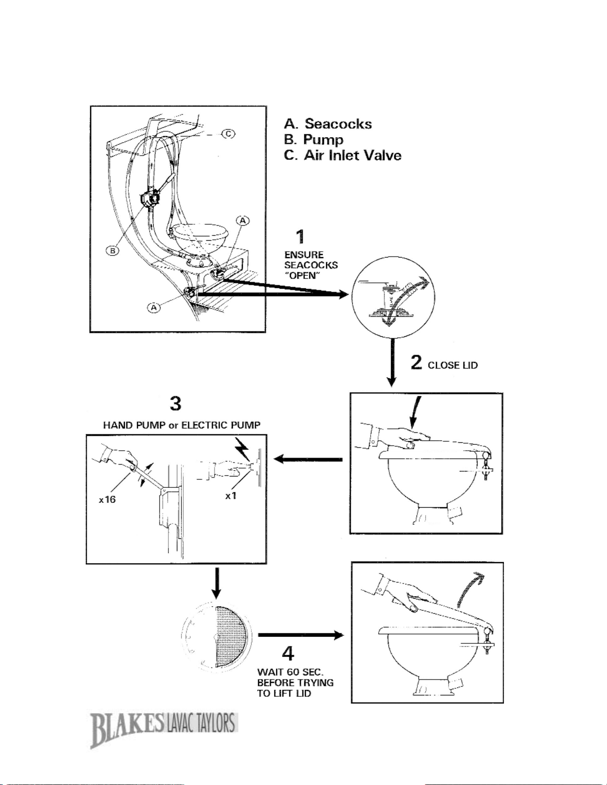
The Lavac is one of the most simple to
operate marine toilets available. After use,
the seat and lid are closed and the pump is
then operated for 14-16 strokes (For full
instructions see page 21). As waste is
pumped out, the bowl is sealed causing a
vacuum which draws in the flushing water.
It’s as simple as that!
Within this handbook you will find informa-
tion and practical help on installing, running
and maintaining your Lavac. If you require
any further help or advice, please contact
us either by:
Telephone: +44 (0)1489 580580
Fax: +44 (0)1489 580581
E-mail: info@blakes-lavac-taylors.co.uk
or by writing to:
Blakes Lavac Taylors
13 Harvey Crescent
Warsash
Southampton
SO31 9TA
United Kingdom
Over many years we have taken advice from
sailors around the world concerning their
requirements for marine equipment and our
current range is a result of this ongoing com-
mitment. If you have any comments or help-
ful hints that you would like to share with us,
we would be very pleased to hear from you.
Installation kit provided with your lavac
All Lavac marine toilets are provided wit the
following parts for installation.
zPump – Hand (T/A: On Bulkhead; U/D:
Behind Bulkhead) or Electric (12 volt DC
or 24 volt DC, including wiring loom, time
switch, fuse and fuse holder)
zPlastic Bleed Plugs (Spares No.
TLZ9251)
zSelf adhesive operating instructions
zOwners Handbook.
Because the nature of an installation varies
from owner to owner, certain components
are easier to source locally. We therefore
feel it is best for you to purchase the follow-
ing separately, depending on your require-
ments.
z4 x 6mm (¼“) diameter Stainless Steel
securing bolts or screws for base
z4 x 6mm (¼“) diameter Stainless Steel
securing bolts or screws for pump
zReinforced sanitation grade hose –
length dependant on installation:
19mm (¾“) bore for inlet
38mm (1½“)bore hose for outlet
zHose clips

3
The Lavac System
General
The well known Lavac system is unique
and probably the only single action, above
or below water line, marine WC.
The Lavac has a china pan and is available
as either hand or electrically operated. On
the electric models 12 or 24V DC can be
supplied.
To flush simply close the lid and operate a
single pump. Pressure is reduced in the
bowl as waste goes out and flushing water
is drawn in. A small air bleed valve in the
inlet pipe prevents siphoning.
The particularly hygienic operation and
quietness are characteristics which in
themselves make Lavac a popular choice
for discerning owners. Simplicity of opera-
tion, robustness and reliability are further
important features.
By using a diverter valve the Lavac’s pump
can also be used for other pumping opera-
tions, such as shower tray discharge, bilge
pumping or discharge of the holding tank
(see page 20).
Because legislation is now prohibiting over-
board discharge from toilets, or at least
making it impractical, this edition of the
Lavac owners handbook now gives guid-
ance on holding tanks (see pages 18).
Features
zEasy and versatile in installation.
zCan be mounted under bunk or locker
and pulled out for use.
zPump, separate from bowl, can be
mounted in most convenient position
(above bowl consistent with instructions).
For installation behind bulkhead, a spe-
cial hand pump option is available (see
illustration on p.9).
zParticularly quiet and hygienic in opera-
tion.
zPump can also empty holding tanks, be
used as a bilge pump and/or shower
tray discharge pump.
zAny type of paper can be used,
although tissue is recommended.
zVirtually no maintenance.
zQuick release pump cover for easy
access.
zSingle action operation.
zExceptionally sturdy and durable.
zFull flow valve system.
zLow water usage.
zRemote holding tank installation (if cho-
sen).
zA water seal is the only certain and
complete way of preventing odour from
the waste pipe and/or holding tank.
Electric – Extra Features
zOnly marine toilet to offer manual back-
up with electric version
(see page 17).
zExtremely quiet in operation.
zFully marinised, automatic, adjustable
time switch
4
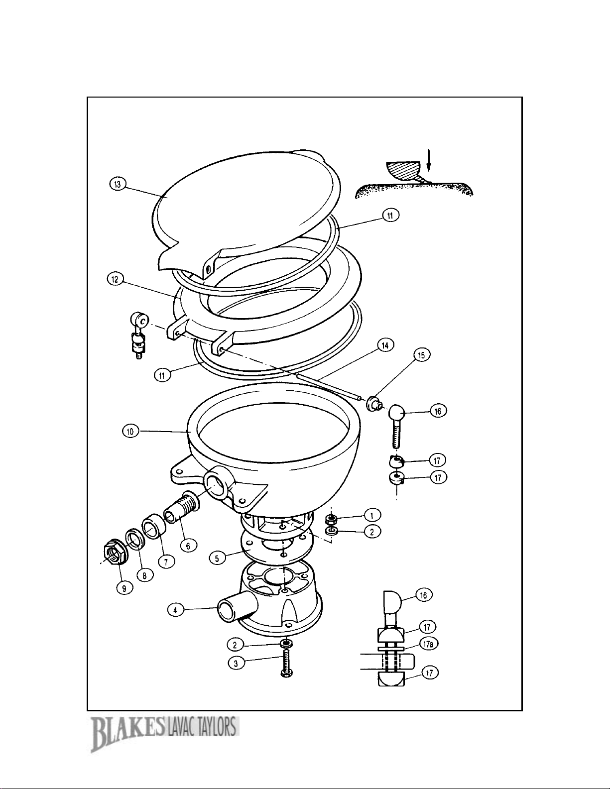
Exploded diagram of the Lavac Zenith
PRODUCT UPDATE
New Thermo-set seal (11) introduced July 1993
with no joins or weld points. Cross-section
below showing longer sealing lip conforms bet-
ter to contact surface (seat or bowl) for
improved vacuum.
PRODUCT UPDATE
New white rubber washer for dome nut.

5
Dimensions and specifications
Lavac Zenith toilet
zBowl – vitreous china for easy
cleaning and durability
zPedestal – injection mould uPVC.
Outlet can be set to either side or rear
of toilet.
zSeat and Lid – special purpose
plastic mouldings.
zHinge assembly – injection moulded
acetal. Stainless steel hinge pin.
zToilet connections –
Inlet 19mm (¾“) bore hose.
Discharge 38mm (1½“) bore hose.
Dimensions:
A - 185mm (7.3”) C - 368mm (14.5”)
B - 290mm (11.4”) D - 410mm (16.2”)
Lavac Zenith
Zenith Components
Diagram No Part No Description
1 TBB7215 x 4 M6 Nuts
2 TLZ9021 x 4 Pan bolt washers - small
TLZ9022 x 4 Pan bolt washers - large
3 TLZ9022 x 4 M6 x 35 Pan bolt
4 TLZ9005 Pedestral base
5 TLZ9010 Pan base joint
6, 7, 8, 9 TLZ9031 Spigot assembly
10 TLZ9025 Zenith pan
11 TLZ9065 x 2 Seals for seat and lid
12 TLZ9070 Zenith seat
13 TLZ9075 Zenith lid
14 TLZ9405 Zenith hinge pin
15(x2), 16(x2) TLZ9056 Hinge set
17(x4), 17a(x2)
Lavac Zenith - Accessories
Part No Description
TLZ9096 Clip for pump handle (38)
TLZ9310 Diverter (two-way) valve
TLZ9460 Bulkhead plate and shroud for U/D pump

6
Exploded diagram of the Lavac Popular

7
Dimensions and specifications
Lavac Popular toilet
zBowl – vitreous china for easy
cleaning and durability
zPedestal – injection mould uPVC.
Outlet can be set to either side or rear
of toilet.
zSeat and Lid – special purpose
plastic mouldings.
zHinge assembly – injection moulded
acetal.
zToilet connections –
Inlet 19mm (¾“) bore hose.
Discharge 38mm (1½“) bore hose.
Dimensions:
A - 185mm (7.3”) C - 343mm (13.5”)
B - 352mm (13.9”) D - 416mm (16.4”)
Lavac Popular
Popular Components
Diagram No Part No Description
4 TLZ9005 Pedestal base
5 TLZ9010 Pan base joint
51 TLZ8015 x 4 M6 x 50 Pan bolt
TLZ8010 x 4 Plastic covers
TLZ8022 x 4 Plastic washer
TLZ8021 x 4 Stainless steel washer
TLZ8020 x 4 M6 nuts
52 TLZ8025 Popular pan
53 TLZ8031 Popular inlet spigot
54L, 54R. 55(x2) TLZ8056 Hinge set
56 TLZ8065 Popular seat seal
57 TLZ8066 Popular lid seal
58 TLZ8070 Popular seat
59 TLZ8075 Popular lid
Lavac Popular - Accessories
Part No Description
TLZ9096 Clip for pump handle (38)
TLZ9310 Diverter (two-way) valve
TLZ9460 Bulkhead plate and shroud for U/D pump

8
Note:
Bulkhead plate and shroud for the
U/D pump (makes a neat, flush
installation – Spares No: TLZ9460,
see installation diagram on p.15).
U/D Pump
Handle Position T/A Pump
Handle Position
Exploded diagram of Hand Pump

9
Dimensions and specifications
Hand Pump
zDiaphragm type
zInjection moulded plastic body
zStainless steel fastenings and handle
zAll rubber components of oil resistant
nitrile
Lavac Zenith & Popular Hand Pump
Components
Diagram No Part No Description
20 TLZ9110 Diaphragm
21 TLZ9175 x 8 2BA x 1” Bolts
TLZ9181 x 8 2BA nuts
22H TLZ9330 Inlet valve - hand
TLZ9335 Inlet valve plate
23 TLZ9320 Front cover
24 TLZ9325 Front cover seal
25 TLZ9125 Eye bolt nut
26 TLZ9100 Top cover complete with valves
27 TLZ9340 Outlet valve
28 TLZ9345 x 2 Outlet valve screws - long
TLZ9350 x 2 Outlet valve screws - short
29 TLZ9115 x 2 Diaphragm plates
30 TLZ9120 Eye bolt
35 N/A Not available as spares item
36 TLZ9406 Rocker arm hinge pin
TLZ9408 x 2 Circlips (rocker arm pin)
37 TLZ9450 U/D Rocker arm
38 TLZ9265 Pump handle
39 TLZ9455 T/A Rocker arm
Hand pump
Dimensions:
A - 170mm (6.6”) C - 140mm (5.5”)
B - 200mm (7.9”)
10
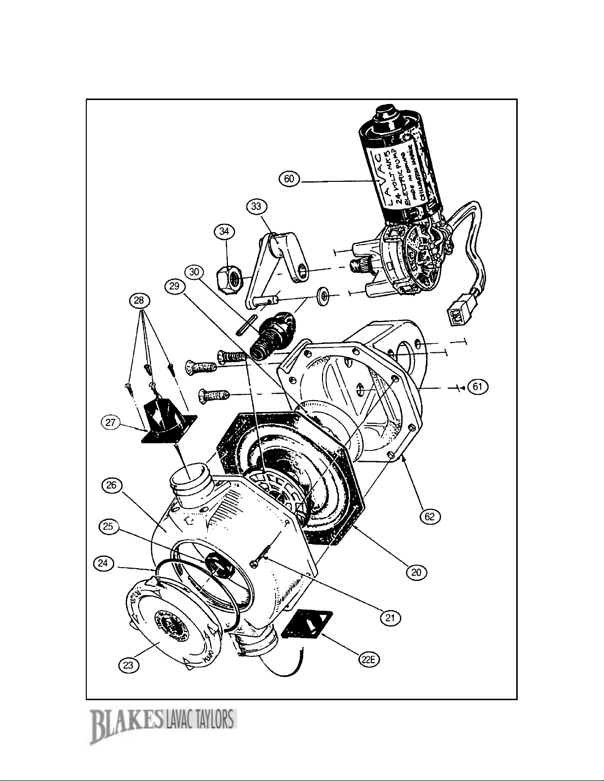
Exploded diagram of the electric pump – 12&24 Volt
11
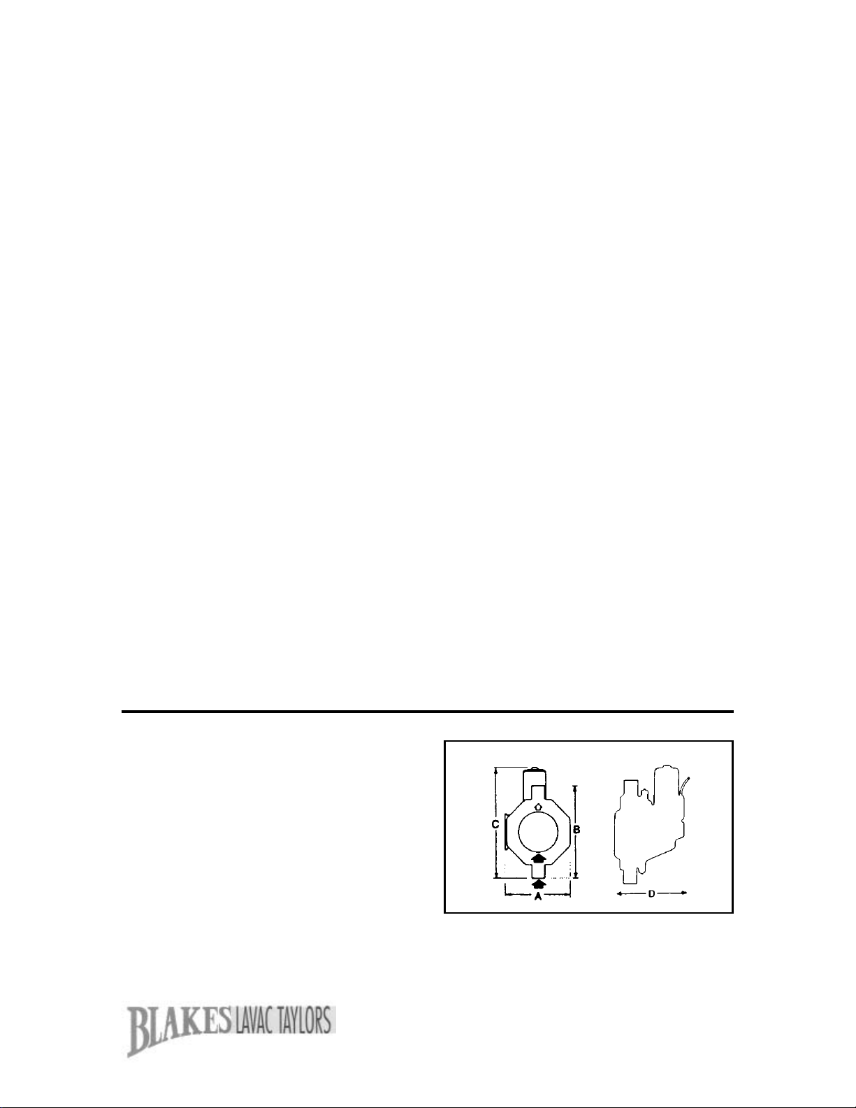
Dimensions and specifications
Electric pump
zDiaphragm type 12V or 24V DC
zInjection moulded plastic body
zAlloy crancase
zStainless steel crank mechanism with
plain bearing
zConsumption 5 amps at 12v under
load. - 5 amp fuse supplied
zWeight 4Kg
zFlow / delivery rate 6 gal per min
Lavac Zenith & Popular Electric Pump
Components
Diagram No Part No Description
20 TLZ9110 Diaphragm
21 TLZ9175 x 8 2BA x 1” Bolts
TLZ9181 x 8 2BA nuts
22H TLZ9330 Inlet valve - hand
TLZ9335 Inlet valve plate
23 TLZ9320 Front cover
24 TLZ9325 Front cover seal
25 TLZ9125 Eye bolt nut
26 TLZ9100 Top cover complete with valves
27 TLZ9340 Outlet valve
28 TLZ9345 x 2 Outlet valve screws - long
TLZ9350 x 2 Outlet valve screws - short
29 TLZ9115 x 2 Diaphragm plates
30 TLZ9120 Eye bolt
33 TLZ9421 Crank assembly
60 TLZ9290 12V Motor
TLZ9295 24V Motor
61 TLZ9185 x 4 M5 x 22mm bolts
62 TLZ9156 Crank case
Electric pump
Dimensions:
A - 178mm (7”) C - 278mm (11”)
B - 223mm (8.8”) D - 225mm (10”)

12
Lavac Zenith
Description Part No Hand pump kit 12 or 24V electric
pump kit
TLZ0954 TLZ0952
Hand pump spares kit
Electric pump spares kit
Pan base gasket (5)
Sealing washer for inlet spigot (7)
Rubber washer (17a)
Hinge bush (15)
Seal for seat and lid (11)
Handbook
TLZ0951
TLZ0956
TLZ9010
TLZ9035
TLZ9054
TLZ9060
TLZ9065
TLZLIT
1
-
1
1
2
2
2
1
-
1
1
1
2
2
2
1
Zenith spares kits
Lavac Popular
Description Part No Hand pump kit 12 or 24V electric
pump kit
TLZ0854 TLZ0852
Hand pump spares kit
Electric pump spares kit
Pan base gasket (5)
Hinge pad (55)
Seal for seat (56)
Seal for lid (57)
Handbook
TLZ0951
TLZ0956
TLZ9010
TLZ8061
TLZ8065
TLZ8066
TLZLIT
1
-
1
2
1
1
1
-
1
1
2
1
1
1
Popular spares kits
13
Lavac operation

14
Installation – seacocks
Siting and installing the seacocks
Having chosen the type of inlet and
discharge seacocks required for
your particular needs, they should
be mounted in the hull. We recom-
mend Blakes Seacocks for use with
our marine toilets. The inlet is
19mm (¾“) and the outlet is 38mm
(1½“).
The inlet seacock should be about
460mm (18“) below the water line
and forward of the discharge sea-
cock. On a sailing vessel, the dis-
tance below the water line may
have to be more to allow for heel-
ing. The discharge seacock should
also be below the water line but
need not be as deep as the inlet.
The location of both seacocks should
be convenient for attaching piping to
and from the toilet and easily acces-
sible for turning off. Ensure that they
are positioned to accept the hoses
before drilling the holes to accept the
fixing bolts.
Fitting the seacocks to the boat.
For fibre-glass boats (Glass
Reinforced Plastic) we recommend
the fitting of a wooden pad, bonded
to the hull, slightly greater in diame-
ter than the seacock flange and
13mm to 19mm (½“ to ¾“) thick(see
fig. 1). To ensure watertight joints on
Fig. 1
¾“ INLET SEACOCK WITH STRAINER
CHAMFER
EDGE
WOODEN
PAD
GRP
HULL
GRP hulls, a small amount of under-
water sealing compound should be
put between the inside skin and this
pad and also under the seacock
flange
For wooden hulls, ensure that
drilling is carried out in the centre of
a hull plank.
For steel hulls. (see fig. 2, the sea-
cocks must not under any circum-
stances be bolted directly onto the
hull. They should be isolated with a
gasket and studded with stainless
steel fittings. This is to prevent elec-
trolytic action.
For aluminium (alloy) hulls, special
aluminium seacocks should be used.
Plastic seacocks are often used but
are not recommended by Lloyds
because of the possibility of melting
in the event of a fire.
Seacock spigots should be cut off to
suit the outside of the hull. The inlet
seacock should be flush with the out-
side of the hull and a strainer fitted.
Similarly the discharge seacock
should protrude to enable it to take
the discharge plate.
Fig. 2
RUBBER or
NEOPRENE
STUD
STEEL HULL
PAD WELDED
TO HULL

15
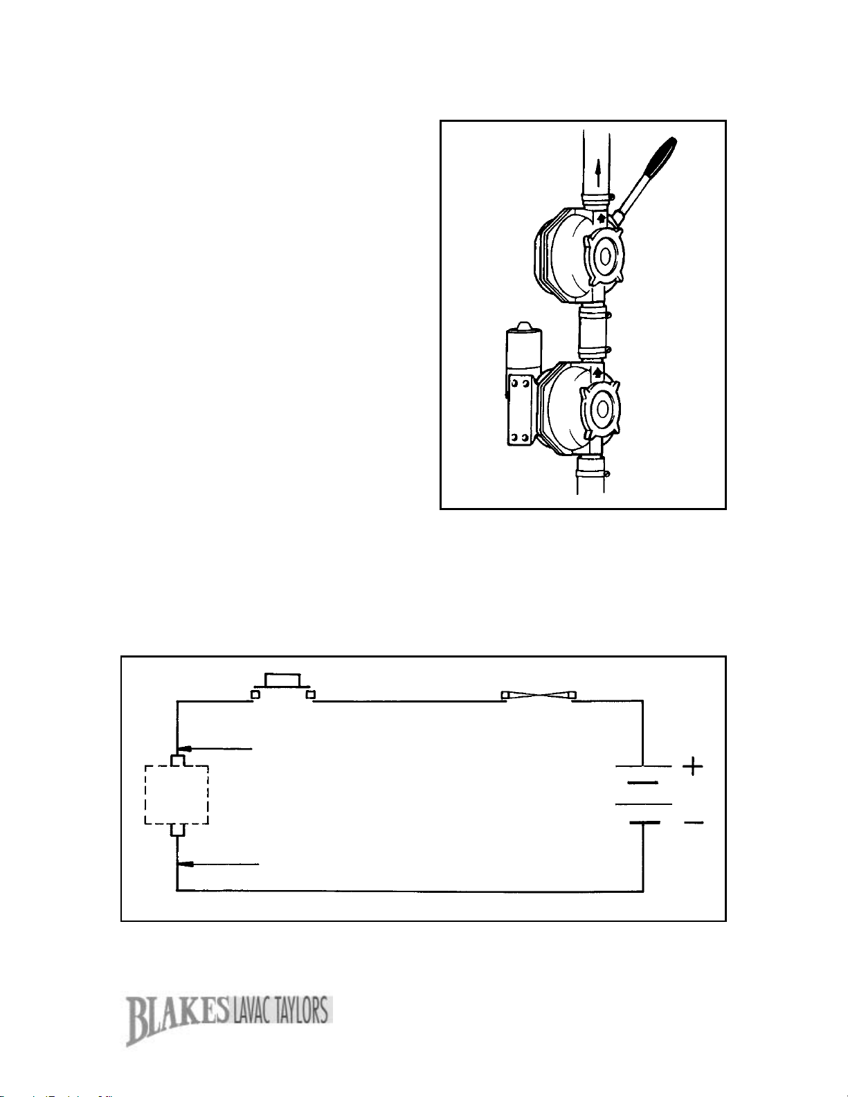
Lavac Installation
Summary
1. INLET SEACOCK
Should be mounted forward of the
discharge to avoid recirculating
waste. We recommend the use of
Blakes seacocks.
2. PUMP (Hand or Electric)
Diagram on the right shows a U/D
hand pump installation with U/D
pump plate and shroud. The pump
(hand or electric) must be mounted
so that the water flow is vertically
upwards through the pump as
shown. The bottom of the pump
must not be mounted at a lower
level than the top of the bowl.
3. AIR BLEED VALVE
A simple plastic plug with a hole
drilled into it. The plug allows air
into the system, preventing siphon-
ing and releasing the vacuum when
pumping stops. The size of the hole
in this valve controls the level of
water remaining in the bowl. Two
valves with different sized holes are
provided (Spares No. TLZ9251 –
the larger the hole, the less water
remains in the bowl.
4. DISCHARGE SEACOCK
5. BOWL
The outlet at the rear of the bowl
can be positioned to the left, right or
centre. This can be very helpful for
difficult installations.
6. U/D PUMP
Makes a neat, flush installation.
7. HANDLE CUP
Typical installation
Siting and installing the Lavac
1. The Lavac base should be
mounted on a hardwood or fibre
glass platform approximately 32mm
(¼“) thick. A template should be
used for drilling the holes necessary
in the platform.
2. Securing bolts 6mm (¼“) should
be used to hold down the toilet. Do
not fix the toilet at this point. It is
advisable to wait until the hoses are
fixed and installation checked.
3. We recommend the use of rein-
forced sanitation grade hose for the
Lavac installation. Avoid sharp
angled or acute bends in either the

16
Lavac Installation Handle position (angle of operation) and/or outlet
direction can be varied by rotating pump body
(26) relative to back cover (35) (See exploded
diagram p.8).
If back cover (35) is rotated ensure air bleed hole
in back cover is re-drilled at lowest point.
DIRECTION OF
OUTLET
therefore all hose clips must be
tight.
8. An important part of the Lavac
installation is the air bleed valve
which has to be located at the top
of the loop of the inlet pipe. Drill a
5mm (1/18”)diameter hole at the
top of the curve of the inlet pipe If
the top of the inlet pipe is in a
clothing locker, ensure that the
clothes do not obstruct the air
bleed valve. Similarly, if the hose
is hard up below the deck, drill the
hole slightly to one side at the top
of the loop. For installations on or
above the water line, insert the
white plastic bleed plug.
For installations below the water
line, use the black plastic plug.
(Set of bleed plugs TLZ9251).
9. Attach the self-adhesive oper-
ating instructions to the bulkhead
near the pump. We recommend
that a suitable rubber stop is
placed on the bulkhead behind the
Lavac unit to avoid possible dam-
age to the lid when opened.
inlet and, particularly, the outlet
hoses. If it is completely unavoid-
able to use right angled fittings in
the outlet hose, then rigid plastic fit-
tings should be used having an
inside radius of not less than 31mm
(2“). Do not use sharp angled
plumbers fittings which can easily
cause a blockage.
4. Establish a position for the pump
where the pump inlet is no lower
than the bowl top.
5. Bolt or screw the pump in posi-
tion using 6mm (¼“) diameter bolts
or screws ensuring that the flow
arrow on the pump is vertically up
or certainly not more than 45° from
the vertical.
IF THE PUMP IS MOUNTED IN
ANY OTHER WAY THE INSTALLA-
TION WILL BE INEFFICIENT IN
OPERATION AS THE INLET VALVE
CANNOT SEAL EFFECTIVELY.
6. Cut the 38mm (1½“) diameter
outlet hose to the lengths required.
Be sure to allow enough hose from
the top of the pump to take the loop
above the waterline at maximum
heel of the boat. For motor vessels
this is high enough at maximum
angle of roll. Attach the two cut
lengths of hose from the bowl to the
bottom (inlet) of the pump and from
the top of the pump (outlet) to the
outlet seacock.
7. Connect the 19mm (¾“) bore
inlet hose to the bowl inlet, having
allowed for a loop similar to the outlet
(see point 6) and attach the inlet
hose to the inlet seacock.
PEASE NOTE: It is absolutely
essential that all joints are 100%
sealed. No air leakage is permissible
17
Lavac Electric pump Installation
1. Connect up wiring as indicated in the
diagram. The time switch should be
mounted through the bulkhead so that
only the front flange with push button and
shroud are visible to the user. Use only
stainless steel screws.
2. The time switch is set for 30-45 sec-
onds. If you wish to adjust the operating
time (inlet pipe length will vary between
installations), turn the small screw in the
centre of the back of the switch very
slightly in a clockwise direction to length-
en the time and anti-clockwise to reduce
it (time switch is adjustable between
approx 1 second and 10 minutes).
3. Ensure when mounting the pump
that the flow arrows are facing upwards.
Do not mount in a horizontal position.
Also ensure that the pump is no lower
than the top of the bowl.
4. WARNING. Do not operate the
switch while using the toilet. As a precau-
tion, mount the switch in such a position
that children cannot reach it until after
use.
The Electric Lavac can be fitted with
a standby manual pump to provide
emergency back up. It is easy to
upgrade existing hand toilets to elec-
tric or add a standby pump to elec-
tric toilets.
BLACK or BLUE LEAD
RED or BROWN LEAD
TERMINAL BLOCK
ON PUMP MOTOR
12 OR 24 VOLT
BATTERY
(OR DC SUPPLY)
5 AMP FUSE
+ HOLDER
MINIMUM WIRE SIZE 30/.25 (30 STRANDS/0.25mm)
PUSH-BUTTON
TIME SWITCH
(Loom) {Black/Blue - Black/Blue}(Pump)
Red/Brown - Red/Brown

18
Holding Tanks – General
Options
Recirculating pump out – often used
for a conversion installation where
the toilet compartment is sufficiently
roomy. The holding tank is usually
integrated with the toilet head, but
with the Lavac used in a recirculat-
ing system the holding tank can be
remote.
Fresh Water Flush with Pump-Out
Holding Tank – probably the most
acceptable system to the user.
Allows for a larger tank installation,
as the tank can be positioned any-
where in relation to the toilet head.
Holding Tank Capacity
If sink and shower waste is also
being contained the holding tank
must be substantially larger. Used
with care, a shower will require
about three gallons each time it is
used. Obviously both sink and
shower waste quantities depend
entirely on how the facilities are
used, as well as the frequency of
use. The size of a holding tank is
entirely dependent on the berth/size
of the boat and anticipated duration
between pump-outs. A holding tank
can never be too large but it can
easily be inconveniently small.
Restriction on size depends on
available space for installation and
effect on the boats trim. The follow-
ing formula will provide an approxi-
mate guide to the minimum size of
tank which is acceptable:
zBerths x days between pump-out
x Y = gallons capacity of tank.
zFor recirculating systems factor Y
=0.5
zFor fresh water flush systems factor
Y = 2.5
These calculations assume low water
use toilets are being used.
Materials
If a holding tank system is being
considered, some careful thought
must be given to the design and
construction of the tank. Four
materials are commonly used for
holding tank construction,
polypropylene, glass fibre, stain-
less steel and galvanised steel.
Polypropylene – the smooth inter-
nal and external finish of this
material has the benefit of prevent-
ing matter from adhering to the
walls of the tank and at the same
time presenting a clean, trim
appearance.
Glass Fibre – provides consider-
able flexibility in design and is
easy to alter during or after instal-
lation, should the need arise.
Stainless Steel – is strong and
resistant to corrosion but is expen-
sive, in both material and con-
struction.
Galvanised Steel – provides the
cheapest solution but is not totally
corrosion resistant. Once corrosion
starts it spreads rapidly.
Flexible Tanks
Flexible tanks are very easy to
install in retrofit situations. Ideal on
craft where holding facility is sel-
dom used, but two points should
be considered carefully:
(i) If the boat is likely to encounter
much sea movement then flexible
tanks are prone to wear and chaffe
(ii)some materials, although fluid-
tight, will omit odour and a suitable
grade flexible tank must be used.

19
Holding Tanks – Lavac
Economy of Flushing Water
Economy of flushing water is a valu-
able Lavac characteristic for holding
tank installations. This is also impor-
tant when flushing water is being
drawn from the craft’s own water tank.
Using the on-board fresh water supply
for flushing should be seriously con-
sidered. It prevents scaling in the sys-
tem from salt water and dirty/oily water
entering the bowl. The Lavac uses
approximately only 3 pints of flushing
water per operation. With the electric
Lavac, the quantity of flushing water
can be controlled accurately by the
time switch. This may be helpful for
owners frequently entertaining visitors
inexperienced on boats. Two time
switches can be used if a long and
short flush option is thought worth
while.
Flexibility
Lavac provides the facility to site
tanks anywhere in the boat. Therefore,
as well as making maximum use of
the tank capacity, because of the
economy of flushing water used, the
holding tank can be housed where
space is less critical, allowing a larger
tank to be installed than is possible
with some other systems. With the
Lavac system it is practical to install a
high tank. Why not consider, for exam-
ple, a full height floor to roof bulkhead
tank? (This can be in conjunction with
either sea water or fresh water flush
systems).
Diverted Pump Action
In conjuction with a two-way valve, it
can carry out other tasks. See figs 2, 3
and 4 on pages 21 and 22. Fig. 5
shows how this saves the cost of a
separate pump and hull fitting.
Ideal for Recirculating System
Although the Lavac has ideal features
for fresh water flushing systems, in
extreme circumstances it may be pre-
ferred to minimise the holding tank
size and operate a recirculating sys-
tem. Lavac, incorporating a sealed
seat and lid to the bowl, reduces
odour considerably below levels
encountered with other recirculating
toilet systems. If the Lavac is being
used on a recirculating principle, the
flushing water pick up pipe, in the
holding tank, must be surrounded by a
fine aluminium or brass gauze filter.
Vacuum Fragments Waste
The vacuum fragments waste as it
passes through the base opening.
Solid matter will remain in suspension
in the tank, thus allowing more effi-
cient tank emptying. This eliminates
the need for a macerator. Macerators
are best avoided if possible because
their mechanically operated cutting
blades can be jammed with even small
objects. Macerators are also very
noisy!

20
Holding Tank Plumbing
Key Points
zFor all systems where pump-out
via deck fitting, or via seacock,
is not required either can be
omitted.
zIf Holding Tank is above the
waterline no pump is required
for discharge to sea, i.e. open
seacock to drain, close to hold.
(Also open seacock to allow dis-
charge to sea via the tank,
direct from toilet. Tank outlet
must be installed at bottom of
tank and fall continuously to
seacock).
zWhen inlet or Outlet Hoses are
plumbed overboard, to a below-
waterline position, they must be
looped above the waterline to
prevent siphoning (If toilet is
below the waterline).
zBall Check Valve for ¾“ bore hose
(only required if draw is more than
36“ below toilet) or vented loop
required if toilet is below waterline.
Useful statistics
zOne cubic foot contains 6 gallons.
zOne gallon contains 1/6cubic feet.
zOne gallon of water weighs 10 lbs.
Fig. 1
Suggested Systems
1 - For craft permanently on
waters where overbard discharge
is prohibited. This is a basic sys-
tem. Use of a dock side marina
pump out station is used or a DIY
outboard pump can also discharge
the holding tank.
A Toilet discharge flow
B Pump-out flow to quay
C Discharge to sea
1. Vent/breather pipe connect to 1”
ID hose
2. Microvent filter (see p.20)
3. Rinse-out facility connect to ID
hose
4. Ball check valve or vented loop.
5. Seacock
Pump-out deck fitting
Vented Loop
‘T’ Connection
Lavac Pump. Hand
and/or Electric
Self pump-out
inboard pump
Hand or
Electric
Flush
water
intake
B/C
HOLDING TANK
LAVAC
TOILET
This manual suits for next models
2
Table of contents
Other Toplicht Toilet manuals

Popular Toilet manuals by other brands


Kohler
Kohler Sterling Windham 402015 manual

Invacare
Invacare H304 Finesse user manual

Vetus
Vetus HATO212B Installation instructions and operation manual

SUNWIND
SUNWIND El-dorado 720100 user manual

Villeroy & Boch
Villeroy & Boch 9M77C1 quick start guide

Kohler
Kohler JULY S-TRAP K-28866T-S quick start guide


