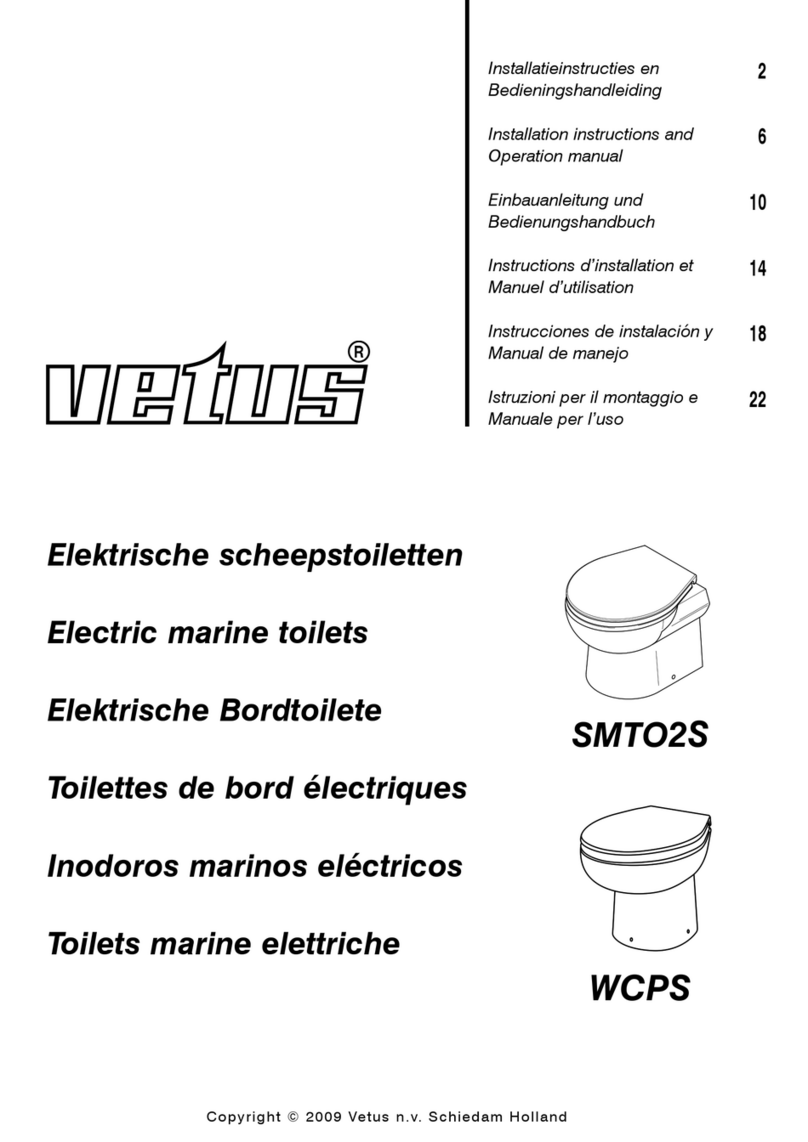
Vetus HATO212B Troubleshooting guide

Copyright © 2008 Vetus n.v. Schiedam Holland
Elektrische scheepstoiletten
Electric marine toilets
Elektrische Bordtoilete
Toilettes de bord électriques
Inodoros marinos eléctricos
Toilets marine elettriche
HATO212B
HATO224B
HATO110
HATO220
Installatieinstructies en
Bedieningshandleiding
Installation instructions and
Operation manual
Einbauanleitung und
Bedienungshandbuch
Instructions d’installation et
Manuel d’utilisation
Instrucciones de instalación y
Manual de manejo
Istruzioni per il montaggio e
Manuale per l’uso
2
10
18
26
34
42

2 110128.01 Elektrische scheepstoiletten HATO...
1 Inleiding
De Vetus toiletten type ‘HATO...’ zijn toiletten met een geïnte-
greerd vermaalsysteem. Bij correcte installatie en gebruik func-
tioneren deze toiletten als een normaal toilet.
Let op!
Het Vetus toilet mag alleen gebruikt worden voor het ver-
malen en afvoeren van faecaliën en toiletpapier.
Het toilet is niet geschikt voor het vermalen van vreemde
voorwerpen zoals watten, tampons, maandverband, con-
dooms en haren, of het wegpompen van vloeistoffen
zoals olie. Dit kan schade veroorzaken!
Zorg altijd voor een paar rubberhandschoenen aan boord.
2 Werking
12 V / 24 V: Na het bedienen van een van de druk-
knoppen wordt de betreffende cyclus
automatisch uitgevoerd.
Er kan gekozen worden tussen de 'ECO'
cyclus deze duurt ongeveer 10 seconden
en de 'NORMAL' cyclus deze duurt onge-
veer 20 seconden.
120 V / 230 V: Wanneer de drukknop op de toiletpot
wordt ingedrukt, wordt de cyclus automa-
tisch uitgevoerd.
De totale cyclus duurt ongeveer 25 secon-
den.
Deze cyclus bestaat uit:
• Een spoelfase:
Het magneetventiel laat gedurende een bepaalde tijd een
hoeveelheid water door. Dit water stroomt de toiletpot in.
• Een maal/ pompfase:
De motor drijft de messen en de pomp aan. De faecaliën en
het toiletpapier worden nu vermalen en weggepompt.
• Fase waarin het waterslot opnieuw op peil wordt gebracht:
Het magneetventiel laat gedurende een bepaalde tijd een
hoeveelheid water door. Dit water vormt het waterslot en
zorgt er voor dat er geen stank vrijkomt.
3 Veiligheid
Zorg ervoor dat tijdens het onderhoud of een eventuele repara-
tie de stroomtoevoer uitgeschakeld is.

110128.01 3
Elektrische scheepstoiletten HATO...
NEDERLANDS
A Draadeinden 4x
B Moeren 8x
C Ringen 6x
D Kunstof sokken 2x
E Pakking 1x
G Terugslagklep 1x
H Slangklemmen 2x
L Kunststof ringen 2x
M Kunststof afdekdoppen 2x
N Voetplaten 2x
O Frame 1x
P Toilet 1x
Q Reduceerstuk 1x
4 Leveringsomvang 12 V / 24 V 4 Leveringsomvang 110 V / 230 V
A4x B8x C6x D
E1x G1x H2x
L2x M2x 2x
SW17
N
2x
1x
O P 1x
1x
Q
ø 32
ø 19
HATO 01B
5 Installatie
5.1 Algemeen
Voor installatievoorbeelden, zie pagina 50.
Installeer het toilet altijd volgens de geldende regels van het
desbetreffende land. In sommige gebieden mag het toilet niet
direct in het water lozen!
Let op!
Installeer het toilet altijd in combinatie met het meegeleverde
frame.
Voordat met de installatie van het toilet wordt begonnen, verze-
ker u ervan dat de wand waartegen het frame gemonteerd wordt
stevig genoeg is.
A Draadeinden 4x
B Moeren 8x
C Ringen 6x
D Kunstof sokken 2x
E Pakking 1x
F Rubber mof 1x
G Terugslagklep 1x
H Slangklemmen 2x
L Kunststof ringen 2x
M Kunststof afdekdoppen 2x
N Voetplaten 2x
O Frame 1x
P Toilet 1x
Q Reduceerstuk 1x
A4x B8x C6x D
E1x F1x G1x
H2x L2x M2x 2x
SW17
N
2x
1x
O P 1x
1x
Q
ø 32
ø 19
HATO 01

4 110128.01
Elektrische scheepstoiletten HATO...
5.2 Installatie van het frame
Demonteer de pot van het frame.
Schroef de draadeinden (A) uit tot
een lengte van 50 mm + ‘x’.
(‘x’ = de wanddikte, bijv. gips-
plaat + tegels)
Borg de draadeinden (A) met de
moeren (B).
Schuif de kunststof sokken (D)
over de draadeinden (A).
Plaats het frame tegen de wand.
Plaats de pot over de draadein-
den.
Monteer de pot tijdelijk met de
kunststof ringen (L) en de moeren
(B).
Schroef 2 moeren (B) over de
draadeinden en schroef de voet-
platen (N) over de draadeinden.
Borg met één moer (B) de voet-
plaat (N).
Draai de verstelbare voeten in het
frame.
Stel de gewenste hoogte van de
pot in met de verstelbare voeten.
Bepaal met behulp van een
waterpas of het frame horizontaal
staat.
Borg de verstelbare voeten met
de moer (B) tegen het frame.
Verwijder de pot van het frame.
Teken met behulp van een pot-
lood de 6 bevestigingsgaten van
het frame af.
Bepaal met behulp van een water-
pas of het frame verticaal staat.
Gebruik eventueel ringen om
ervoor te zorgen dat het frame
volledig verticaal staat.
Let op!
Gebruik bevestigingsmiddelen
(niet meegeleverd) die geschikt
zijn voor de wand waartegen het
frame geplaatst wordt.
Boor de 6 bevestigingsgaten met
de juiste diameter.
Monteer het frame met de juiste
bevestigingsmiddelen tegen de
wand.
Let op!
De afstand tussen de wand en de
voorzijde van het frame mag niet
meer dan 100 mm bedragen.
5.3 Elektrische installatie
Controleer of de spanning, vermeld op het typeplaatje van de
motor, overeenkomt met de boordspanning.
Gebruik accu’s met voldoende capaciteit om een correcte wer-
king van het toilet te verkrijgen.
Sluit de voedingsspanning aan zoals in het aansluitschema is
aangegeven.
Neem in de plus (‘+’) draad een schakelaar en een zekering
op.
Pas draden toe met een minimale doorsnede van 6 mm2(bij
12 V) of 4 mm2(bij 24 V).
5.3.1 Bedieningspaneel (12 V / 24 V)
Monteer de inbouwflens met de pakking in de wand; voor gataf-
metingen zie tekening bij 'Hoofdafmetingen'.
Voer de kabel door de flens naar het toilet en verbind met de
kabel op het toilet. Breng ter bescherming de meegeleverde
behuizing aan over de stekerverbinding.
Klik het paneel in de inbouwflens; let er op dat de o-ring correct
gemonteerd is.
50+x
B
A
HATO 02
D
B
A
L
B
HATO 03
HATO 05
B
B
N
HATO 06
HATO 07
HATO 08
HATO 09
HATO 10
max. 100 mm
HATO 11
B
B
N
A
HATO 04

110128.01 5
NEDERLANDS
Elektrische scheepstoiletten HATO...
5.4 Watertoevoer
Maak van koperen leiding of van
slang de watertoevoer.
Kort de toevoer in tot circa 150 mm
onder het frame.
Zet de toevoer vast met klem-
men.
Voorzie de watertoevoer van een
kogelkraan met een aansluiting
van 3/4” uitwendig.
Zorg ervoor dat de kogelkraan
bereikbaar blijft.
Indien reeds een waterdruksysteem aan boord geïnstalleerd
is, kan de toevoerslang op dit systeem worden aangesloten.
De waterdruk van dit systeem moet echter wel minimaal 1,5
bar zijn; dit is de minimale druk om een optimale spoeling te
verkrijgen.
Wanneer de druk van het waterdruksysteem minder dan 1,5
bar is, of wanneer buitenwater wordt gebruikt als spoelwater,
installeer dan een water toevoerpomp in de toevoerslang. De
capaciteit van de water toevoerpomp dient minimaal 10 liter/
minuut te zijn.
Wanneer buitenwater wordt gebruikt als spoelwater, zorg er dan
voor dat dit water zeer goed gefilterd wordt.
5.5 Afvoer
Gebruik als afvoerleiding slang
ø 19 mm (bijvoorbeeld ‘Vetus
geurdichte vuilwaterslang’ ø 19
mm).
Kort de afvoer in tot circa 180 mm
onder het frame.
Zet de afvoer vast met klemmen.
5.6 Voorkomen van hevelen
Indien het toilet zich onder of minder dan 50 cm boven de
waterlijn bevindt, bestaat het gevaar dat water (toevoer of
afvoer) door de hevelwerking in het toilet kan terugstromen.
Om dit hevelen te voorkomen dient op het hoogste punt in de
toevoer en/of afvoer een beluchter geplaatst te worden (zie
installatievoorbeelden).
5.7 Montage voorzetwand
Plaats de voorzetwand (bv. gips-
plaat) tegen het frame.
Boor op de juiste plaats 2 gaten
ø 25 mm door de voorzetwand,
zodat de voorzetwand volledig
tegen het frame rust.
Voorzie de voorzetwand van een luik. De kogelkraan in de
watertoevoer blijft op deze manier bereikbaar zonder dat de pot
gedemonteerd hoeft te worden.
Plaats de meegeleverde pakking
(E) op de juiste wijze tegen de
voorzetwand (draadeinden door
de gaten van de pakking).
Teken aan de binnenzijde van de
pakking het uit te zagen gat af.
Verwijder de pakking.
Zaag het gat uit de voorzetwand.
Wanneer de voorzetwand wordt
betegeld, dienen de tegels op
dezelfde manier te worden uit-
gesneden als de opening in de
voorzetwand.
Controleer nogmaals of de draa-
deinden de juiste lengte hebben
voordat de pot definitief vastgezet
wordt.
Plaats de pakking (E) over de
draadeinden.
ø25
ø25
HATO 14
HATO 16
HATO 17
HATO 18
E
HATO 19
HATO 15
150
3/4"
HATO 12
(achteraanzicht)
180
ø 19
HATO 13
(achteraanzicht)

5.8 Aansluitingen 12 V / 24 V
5.8.1 Afvoer
Terugslagklep:
Plaats de terug-
slagklep (G) op de
afvoeraansluiting. Zet
de terugslagklep vast
met de slangklem
(H).
Reduceerstuk:
1 Plaats het redu-
ceerstuk (Q) in de
terugslagklep.
2 Zet het reduceer-
stuk vast met de
slangklem (H).
3 Monteer de afvoer-
slang (ø 19 mm).
4 Het reduceerstuk
kan in elke stand
gemonteerd wor-
den. Zodat de
afvoerslang naar
links, rechts, onder
of boven kan wor-
den geleid.
5 Het gebogen deel
van het reduceer-
stuk kan worden
afgezaagd om de
afvoer naar achte-
ren te leiden.
Gebruik als afvoerleiding slang ø 19 mm (bijvoorbeeld ‘Vetus
geurdichte vuilwaterslang’ ø 19 mm).
Zet de afvoer vast met klemmen.
5.8.2 Watertoevoer
De flexibele toevoerslang van het motorhuis is voorzien van een
aansluiting van 3/4”.
Sluit de flexibele toevoerslang aan op de kogelkraan van de
watertoevoer.
5.9 Montage van de pot 12 V / 24 V
Monteer de pot pas definitief wanneer alle aansluitingen zijn
gemaakt.
Zorg ervoor dat de kunststof sokken (D) op de draadeinden
zitten.
Plaats de pot over de draadeinden. Zet de pot tijdelijk vast.
G
H
HATO 22B
Q
1 2
3
H
Q
H
4 5
Q
H
Q
Q
6 110128.01 Elektrische scheepstoiletten HATO...

110128.01 7
Elektrische scheepstoiletten HATO...
NEDERLANDS
5.8 Aansluitingen 110 V / 230 V
5.8.1 Afvoer
Schuif de rubber mof (F) over de
afvoeraansluiting.
Monteer de terugslagklep (G)
met de slangklem (H).
Let op!
De terugslagklep (G) moet ver-
ticaal gemonteerd worden, met
de pijl naar boven.
Reduceerstuk:
1 Plaats het reduceerstuk (Q) in de terugslagklep (G).
2 Zet het reduceerstuk vast met de slangklem (H).
3 Monteer de afvoerslang (ø 19 mm).
5.8.2 Watertoevoer
De flexibele toevoerslang van het motorhuis is voorzien van een
aansluiting van 3/4”.
Sluit de flexibele toevoerslang aan op de kogelkraan van de
watertoevoer.
5.9 Montage van de pot 110 V / 230 V
Monteer de pot pas definitief wanneer alle aansluitingen zijn
gemaakt.
Zorg ervoor dat de kunststof sokken (D) op de draadeinden
zitten.
Plaats de pot over de draadeinden. Zet de pot tijdelijk vast.
5.10 Testen
Draai de kogelkraan in de toevoer helemaal open om een goede
spoeling te verkrijgen. Druk éénmaal op de drukknop, laat hem
los en kijk of de cyclus op de juiste wijze wordt uitgevoerd. Werp
een aantal velletjes toiletpapier in de toiletpot en voer nogmaals
een spoeling door.
Verwijder de pot. Controleer alle aansluitingen op dichtheid.
5.11 Eindmontage
Plaats de pot over de draadeinden.
Plaats nu de kunststof ring (L) en
de moer (B) op de draadeinden.
Draai de moeren vast. Plaats de
kunststof afdekdoppen (M) over
de moeren.
Verwijder overtollige pakking met
een scherp mes.
Kit de overgang van pot op wand
af met een siliconenkit.
HATO 23
F
G
H
F
HATO 20
HATO 22
1 2 3
ø 19
HATO 21
ø 19
G
ø 32
ø 19
Q
G
ø 19
G
H

8 110128.01 Elektrische scheepstoiletten HATO...
6 Gebruik
• Zorg ervoor dat de kogelkraan in de toevoerslang open
staat.
12 V / 24 V: • Er kan een korte of een lange spoeling
worden uitgevoerd:
• Korte spoeling (1,2 liter):
Druk op de 'ECO' druk-
knop.
• Lange spoeling (2,2 liter):
Druk op de 'NORMAL' druk-
knop.
120 V / 230 V: • Druk eenmaal op de drukknop om een
spoeling (5 liter) uit te voeren.
• Draai na het gebruik van het toilet de kogelkraan dicht.
Wanneer het toilet lange tijd niet gebruikt is, is het raadzaam
enkele malen met schoon water te spoelen voordat het toilet
weer in gebruik wordt genomen.
Tijdens vorstperioden (winter) dient u de volgende maatregelen
te treffen:
• Sluit de watertoevoer af (draai de afsluiter dicht).
12 V / 24 V: • Pomp het toilet leeg door op
de toets met het pompsym-
bool te drukken en deze
ingedrukt te houden.
120 V / 230 V: • Voer een cyclus uit zonder water.
• Giet circa 2 liter antivries in de toiletpot.
• Tap de leidingen af.
Antivries is giftig. Loos antivries nooit in buitenwater.
7 Onderhoud
Om het toilet te reinigen en de aanslag in het toilet te verwijde-
ren kunnen de traditionele toiletreinigers gebruikt worden.
Om kalkaanslag binnen het pompdeel te voorkomen dient de
kalkaanslag geregeld te worden verwijderd. Handel als volgt:
• Sluit de watertoevoer af (draai de afsluiter dicht).
12 V / 24 V: • Pomp het toilet leeg door op
de toets met het pompsym-
bool te drukken en deze
ingedrukt te houden.
120 V / 230 V: • Voer een cyclus uit zonder water.
• Giet circa 1 liter azijn of ontkalker in de toiletpot. Laat dit
enkele uren inweken.
• Draai de kogelkraan weer open en voer meerdere cycli uit
om de toiletpot te spoelen en het restwater uit de pomp te
verwijderen.
De frequentie van de ontkalking is afhankelijk van de hardheid
van het water. Ontkalk tenminste tweemaal per jaar.
Gebruik geen producten op basis van natrium (ontstoppers), of
oplosmiddelen.
Indien zeewater wordt gebruikt als spoelwater, dient toch af en
toe met zoetwater te worden gespoeld om zoutafzetting tegen
te gaan.
8 Technische gegevens
Spanning : 12 V 24 V 110 V 230 V
Stroom : 25 A 15 A 9 A 2,8 A
Maximale opvoerhoogte
afvoerslang : 3 meter
Maximale lengte afvoerslang : 30 meter
Pompcapaciteit, bij een
opvoerhoogte van 3 meter : 36 liter/min @ 12 V
43 liter/min @ 24 V
42 liter/min @ 120/230 V
Maximale watertemperatuur : 35˚C
Geluidsniveau : 61 dBA
Bescherming : IP44
Gewicht : 28 kg (incl. frame)
HATO 24

110128.01 9
Elektrische scheepstoiletten HATO...
9 Storingen
Zorg ervoor dat tijdens een eventuele reparatie de stroomtoevoer uitgeschakeld is.
Storing
De motor draait en de cyclus verloopt
correct, maar het water in de toiletpot
wordt te langzaam of helemaal niet afge-
zogen.
De cyclus verloopt cor-
rect, maar na elke cyclus
blijft er een kleine hoeveelheid water in
de toiletpot achter.
De motor maakt een ‘ratelend’ geluid.
Na het indrukken van de drukknop wordt
de cyclus niet uitgevoerd.
De cyclus begint, maar het water stroomt
te langzaam in de toiletpot.
De cyclus begint, maar er stroomt geen
water in de toiletpot.
Mogelijke oorzaak
De beluchterklep sluit niet goed meer af.
De afvoerleiding is verstopt.
De zeefkorf is verstopt.
De afvoerhoogte is te groot.
De afvoerleiding is verstopt
Een hard voorwerp bevindt zich in de
zeefkorf en stoot tegen de draaiende
messen.
Er is geen voedingsspanning aanwezig.
De stekerverbinding van bedieningspa-
neel naar toilet is los.
De besturingselectronica is defect.
De drukknop is niet krachtig genoeg
ingedrukt.
Het transparante slangetje van de druk-
knop zit ergens klem en daardoor kan de
drukschakelaar niet ingeschakeld wor-
den.
De drukschakelaar is defect.
De tijdklok is defect.
Het filter van het magneetventiel is ver-
stopt
De waterdruk is te laag.
De afsluiter van de watertoevoer staat
niet open.
Het magneetventiel is defect.
De waterdruk is te laag.
Oplossing
Reinig de beluchterklep of vervang de
beluchterklep.
Ontkalk de afvoerleiding.
Reinig de zeefkorf.
Wijzig de installatie.
Ontkalk de afvoerleiding.
Demonteer het motorblok en verwijder
het voorwerp uit de zeefkorf.
Controleer hoofdschakelaar en zekering.
Maak de verbinding in orde.
Vervang de besturingselectronica.
De drukknop stevig indrukken en vast-
houden.
Maak het transparante slangetje vrij.
Vervang de drukschakelaar.
Vervang de tijdklok.
Reinig het filter
Zorg voor een waterdruk van minimaal
1,5 bar.
Open de afsluiter.
Vervang het magneetventiel.
Zorg voor een waterdruk van minimaal
1,5 bar.
NEDERLANDS
Storing
De motor draait en de cyclus verloopt
correct, maar het water in de toiletpot
wordt te langzaam of helemaal niet afge-
zogen.
De cyclus verloopt correct, maar na elke
cyclus blijft er een kleine hoeveelheid
water in de toiletpot achter.
De motor maakt een ‘ratelend’ geluid.
Na het indrukken van de drukknop
wordt de cyclus niet uitgevoerd.
De cyclus begint, maar het water stroomt
te langzaam in de toiletpot.
De cyclus begint, maar er stroomt geen
water in de toiletpot.
Mogelijke oorzaak
De beluchterklep sluit niet goed meer af.
De afvoerleiding is verstopt.
Het pomphuis is verstopt.
De zeefkorf is verstopt.
De afvoerhoogte is te groot.
De afvoerleiding is verstopt
Een hard voorwerp bevindt zich in de
zeefkorf en stoot tegen de draaiende
messen.
Er is geen voedingsspanning aanwezig.
De stekerverbinding van bedieningspa-
neel naar toilet is los.
De besturingselectronica is defect.
De drukknop is niet krachtig genoeg
ingedrukt.
Het transparante slangetje van de druk-
knop zit ergens klem en daardoor kan de
drukschakelaar niet ingeschakeld wor-
den.
De drukschakelaar is defect.
De tijdklok is defect.
Het filter van het magneetventiel is ver-
stopt
De waterdruk is te laag.
De afsluiter van de watertoevoer staat
niet open.
Het magneetventiel is defect.
De waterdruk is te laag.
Oplossing
Reinig de beluchterklep of vervang de
beluchterklep.
Ontkalk de afvoerleiding.
Reinig het pomphuis.
Reinig de zeefkorf.
Wijzig de installatie.
Ontkalk de afvoerleiding.
Demonteer het motorblok en verwijder
het voorwerp uit de zeefkorf.
Controleer hoofdschakelaar en zekering.
Maak de verbinding in orde.
Vervang de besturingselectronica.
De drukknop stevig indrukken en vast-
houden.
Maak het transparante slangetje vrij.
Vervang de drukschakelaar.
Vervang de tijdklok.
Reinig het filter
Zorg voor een waterdruk van minimaal
1,5 bar.
Open de afsluiter.
Vervang het magneetventiel.
Zorg voor een waterdruk van minimaal
1,5 bar.
12 V / 24 V120 V / 230 V
12 V / 24 V
120 V / 230 V

10 110128.01 Electric marine toilets HATO...
1 Introduction
Vetus toilets, model ‘HATO...’, are toilets with an integrated
grinding system. Provided that the toilets have been installed
correctly and are used normally they function like a normal
toilet.
N.B.!
The Vetus toilet may only be used for grinding and dispos-
ing of faeces and toilet paper.
The toilet is not suitable for grinding other objects such
as cotton wool, tampons, sanitary towels, condoms, and
hairs, or for pumping away liquids such as oil. This can
cause damage to the installation!
Make sure that there is always a pair of rubber gloves on
board.
2 Working
12 V / 24 V: The particular cycle chosen is carried out
automatically after operating the appropri-
ate button.
A choice can be made between the
‘ECO’ cycle of about 10 seconds and the
‘NORMAL’ cycle that lasts about 20 sec-
onds.
120 V / 230 V: When the button on the toilet pot is
pressed the cycle is carried out automati-
cally.
This lasts for about 25 seconds.
The cycle consists of:
• A flushing phase:
The magnetic valve allows water to run into the toilet for a set
time.
• A grinding / pumping phase:
The motor drives the knife blades and the pump. The faeces
and toilet paper are ground up and pumped away.
• A phase in which the water seal is brought back to the nor-
mal level:
The magnetic valve allows water to run into the toilet for a set
time. This forms a water seal and prevents smells in the toilet
pot.
3 Safety
Make sure that the power supply is switched off when any main-
tenance or necessary repairs are carried out.

110128.01 11
Electric marine toilets HATO...
ENGLISH
A Threaded studs 4x
B Nuts 8x
C Washers 6x
D Plastic socks 2x
E Packing 1x
G Non-return valve 1x
H Hose clamps 2x
L Plastic washers 2x
M Plastic caps 2x
N Foot plate 2x
O Frame 1x
P Toilet 1x
Q Reducing piece 1x
A4x B8x C6x D
E1x G1x H2x
L2x M2x 2x
SW17
N
2x
1x
O P 1x
1x
Q
ø 32
ø 19
HATO 01B
4 Included in the delivery 12 V / 24 V 4 Included in the delivery 110 V / 230 V
5 Installation
5.1 General
See page 50 for installation examples.
Always install the toilet according to the regulations applying for
the country concerned. In some areas the toilet may not empty
directly into the water!
N.B.!
Always use the frame supplied when installing the toilet.
Before starting to install the toilet check that the wall on which
the frame is to be mounted is strong enough to support it.
A Threaded studs 4x
B Nuts 8x
C Washers 6x
D Plastic socks 2x
E Packing 1x
F Rubber sleeve 1x
G Non-return valve 1x
H Hose clamps 2x
L Plastic washers 2x
M Plastic caps 2x
N Foot plate 2x
O Frame 1x
P Toilet 1x
Q Reducing piece 1x
A4x B8x C6x D
E1x F1x G1x
H2x L2x M2x 2x
SW17
N
2x
1x
O P 1x
1x
Q
ø 32
ø 19
HATO 01

12 110128.01
Electric marine toilets HATO...
5.2 Installing the frame
Take the pot off the frame.
Unscrew the threaded studs (A) to
a length of 50 mm + ‘x’.
(‘x’ = the thickness of the wall,
e.g. plasterboard + tiles)
Put bolts (B) on to the threaded
studs (A).
Slide the plastic socks (D) over
the threaded studs (A).
Put the frame up against the wall.
Put the toilet pot on to the thread-
ed studs.
Fit the toilet pot temporarily using
the washers (L) and nuts (B).
Screw 2 bolts (B) onto the thread-
ed studs and screw the footplate
(N) over the threaded studs.
Fix the footplate (N) with one nut
(B).
Screw the adjustable feet into the
frame.
Adjust the feet to give the correct
height for the toilet pot.
Use a spirit level to make sure the
frame is horizontal.
Tighten the nuts (B) to fix the
adjustable feet to the frame.
Remove the pot from the frame.
Use a pencil to mark the positions
of the 6 frame fixing holes.
Use a spirit level to make sure the
frame is vertical.
If necessary use washers to make
sure that the frame is exactly verti-
cal.
N.B.!
Use fixing materials (not supplied)
which are suitable for the type of
wall on which the frame is being
placed.
Drill the 6 holes required using the
correct size drill.
Fit the frame to the wall using suit-
able fixing materials.
N.B.!
The distance between the front of
the frame and the wall must not be
more than 100 mm.
5.3 Electrical installation
Check that the voltage given on the type plate on the motor is
the same as the voltage on board.
Use batteries with sufficient power to guarantee that the toilet
will work correctly.
Connect the power supply as shown in the wiring diagram.
Fit a switch and a fuse in the (‘+’) wire.
Use wires with minimum cross section of 6 mm2(for 12 V) or 4
mm2(for 24 V).
5.3.1 Control panel (12 V / 24 V)
Fit the build-in flange with packing in the wall. See the drawing
in the section ‘Principal dimensions’ for the size of the holes.
Feed the cable through the flange to the toilet and connect it
with the cable on the toilet.
Fit the cover provided over the plug connection for protection.
Click the panel into the build-in flange, making sure that the O-
ring is fitted properly.
50+x
B
A
HATO 02
D
B
A
L
B
HATO 03
HATO 05
B
B
N
HATO 06
HATO 07
HATO 08
HATO 09
HATO 10
max. 100 mm
HATO 11
B
B
N
A
HATO 04

110128.01 13
ENGLISH
Electric marine toilets HATO...
5.4 Water supply
Use copper piping or hoses for
the water supply.
Cut off the water supply pipe at
about 150 mm under the frame.
Clamp the supply pipe firmly.
Fit a ball valve with 3/4” external
connection to the supply pipe and
make sure that this will always be
accessible.
If there is already a pressurised water system on board the sup-
ply hose can be connected to this system. The pressure must
be at least 1.5 bar; this is the minimum pressure required to
allow the toilet to function properly.
If the water pressure system is less than 1.5 bar or if external
water is to be used then a supply pump with capacity of at least
10 litres/minute must be fitted in the water supply pipe.
If external water is to be used then this must be properly fil-
tered.
5.5 Outlet
Use ø 19 mm hose (for example
‘Vetus smell proof outlet hose’
ø 19 mm) for the outlet hose.
Cut off the outlet hose at about
180 mm under the frame.
Clamp the outlet hose firmly.
5.6 Prevention of siphoning
If the toilet is below or less than 50 cm above the waterline there
is a danger of water siphoning back into the toilet either through
the supply pipe or the outlet. An air vent must be fitted at the
highest point in the supply pipe and/or the outlet in order to
prevent siphoning (see the installation examples).
5.7 Fitting a false wall
Position the false wall (e.g. plas-
terboard) against the frame.
Drill 2 holes ø 25 mm through the
false wall in the right place so that
it will be fitted right up against the
frame.
Fit a hatch opening in the false
wall so that the ball valve in the supply pipe will always be
accessible without having to dismantle the toilet pot.
Position the packing supplied (E)
correctly against the false wall with
the threaded studs going through
the holes in the packing.
Draw the hole to be cut out on the
inside of the packing.
Remove the packing.
Cut out the hole in the false wall.
If the false wall is to be tiled the
tiles will have to be cut to fit the
opening in the false wall.
Before permanently fitting the
toilet pot check once more that
the threaded studs have the right
length.
Position the packing (E) over the
threaded studs.
ø25
ø25
HATO 14
HATO 16
HATO 17
HATO 18
E
HATO 19
HATO 15
150
3/4"
HATO 12
(rear view)
180
ø 19
HATO 13
(rear view)

5.8 Connections 12 V / 24 V
5.8.1 Outlet
Non-return valve::
Place the non-return
valve (G) onto the
outlet hose. Tighten
the non-return valve
using the hose
clamp (H).
Reducing piece:
1 Placethereducing
piece (Q) into the
non-return valve.
2 Fix the reducing
piece using the
hose clamp (H).
3 Fit the outlet hose
(ø 19 mm).
4 The reducing
piece can be fit-
ted in any position
so that the outlet
hose can be led
to the left, right,
up or down as
required.
5 The bent part of
the reducing piece
can be sawn off in
order to lead the
outlet behind the
toilet.
For the outlet pipe
use a 19 mm internal diameter hose (such as the ‘Vetus imper-
meable 'no smell" sanitary hose’).
Fix the outlet with clamps.
5.8.2 Water supply
The flexible water supply hose attached to the motor housing
has a 3/4” connection.
Connect the flexible water supply hose to the ball valve on the
water supply pipe.
5.9 Fitting the toilet pot 12 V / 24 V
Do not fit the toilet pot permanently until all the connections
have been made.
Make sure that the plastic socks (D) are on the threaded
studs.
Fit the pot over the threaded studs and fix it provisionally.
HATO 22B
G
H
Q
1 2
3
H
Q
H
4 5
Q
H
Q
Q
14 110128.01 Electric marine toilets HATO...

110128.01 15
Electric marine toilets HATO...
ENGLISH
5.8 Connections 110 V / 230 V
5.8.1 Outlet
Slide the rubber sleeve (F) over
the outlet connection.
Fit the non-return valve (G) using
the hose clamp (H).
N.B.!
The non-return valve (G) must
be fitted vertically with the
arrow upwards.
Reducing piece:
1 Fit the reducing piece (Q) into the non-return valve (G).
2 Tighten the reducing piece using the hose clamp (H).
3 Fit the outlet hose (ø 19 mm).
5.8.2 Water supply
The flexible water supply hose attached to the motor housing
has a 3/4” connection.
Connect the flexible water supply hose to the ball valve on the
water supply pipe.
5.9 Fitting the toilet pot 110 V / 230 V
Do not fit the toilet pot permanently until all the connections
have been made.
Make sure that the plastic socks (D) are on the threaded studs.
Fit the pot over the threaded studs and fix it provisionally.
5.10 Testing
Open the ball valve in the water supply pipe completely so that
there will be a sufficient supply of water for flushing. Press the
button once and check whether the cycle is carried out properly.
Throw a few pieces of toilet paper into the pot and check the
cycle again.
Remove the pot and check that there are no leaks at any of the
connections.
5.11 Final fitting
Position the toilet pot over the threaded studs.
Now place the plastic washers (L) and the bolts (B) on the
threaded studs and tighten up the bolts. Fit the plastic caps (M)
on the nuts.
Use a sharp knife to cut off any
excess packing.
Use silicone sealant to seal the
gap between the toilet pot and
the wall.
HATO 23
F
G
H
F
HATO 20
HATO 22
1 2 3
ø 19
HATO 21
ø 19
G
ø 32
ø 19
Q
G
ø 19
G
H

16 110128.01 Electric marine toilets HATO...
6 Use
• Make sure that the ball valve in the water supply pipe is
open.
12 V / 24 V: • A short or long flush can be used.
• Short flush (1.2 litres):
Press the ‘ECO’ button.
• Long flush (2.2 litres):
Press the ‘NORMAL’ but-
ton.
120 V / 230 V: • Press the button once for one flush
(5 litres).
• After using the toilet shut off the ball valve.
If the toilet has not been used for some time it is advisable to
rinse it with clean water a few times before using it.
The following precautions must be taken during periods of frost
(winter) :
• Shut off the water supply to the toilet.
12 V / 24 V: • Pump the toilet empty by
pressing the button with
the pump symbol and hold-
ing this in.
120 V / 230 V: • Carry out a cycle without water.
• Pour about 2 litres anti-freeze into the toilet pot.
• Drain the pipes.
Anti-freeze is poisonous and must never be drained into the
external water.
7 Maintenance
Traditional toilet cleaners can be used to clean the toilet and to
remove scale.
In order to prevent scale deposits from building up in the pump
these must be removed regularly as follows:
• Shut off the water supply by closing the ball valve.
12 V / 24 V: • Pump the toilet empty by
pressing the button with the
pump symbol and holding
this in.
120 V / 230 V: • Carry out a cycle without water.
• Pour about 1 litre of vinegar or scale remover into the toilet
pot and let it soak for some hours.
• Open the ball valve again and carry out several cycles in
order to flush the toilet pot thoroughly and remove all the
water used from the pump.
How often the scale needs to be removed depends on the hard-
ness of the water, but it should be done at least twice a year.
Do not use products based on sodium (unblocking products)
or solvents.
If seawater is used for flushing the toilet should be rinsed
through with fresh water every so often to prevent salt deposits
from building up.
8 Technical details
Voltage : 12 V 24 V 110 V 230 V
Current : 25 A 15 A 9 A 2.8 A
Maximum vertical lift
in outlet : 3 metres
Maximum hose length: 30 metres
Pump capacity at discharge
height of 3 metres : 36 litres/min @ 12 V
43 litres/min @ 24 V
42 litres/min @ 120/230 V
Maximum water
temperature : 35˚C
Noise level : 61 dBA
Protection : IP44
Weight : 28 kg (incl. frame)
HATO 24

110128.01 17
Electric marine toilets HATO...
ENGLISH
9 Fault Tracing
Ensure that the power supply is switched off during repairs.
Fault
The motor runs and the cycle operates
correctly, But the water is pumped out
very slowly, or not at all.
The cycle runs properly but a small
amount of water remains in the bowl.
The motor makes a rattling noise.
Cycle does not run after the button
is pressed.
The cycle starts but water flows too
slowly into the bowl.
Cycle starts but no water flows into the
bowl.
Possible cause
• The air-relief valve does not shut prop-
erly.
• The outlet pipe is blocked.
• The pump housing is blocked.
• The sieve is blocked.
• The discharge height is too great.
• The outlet pipe iis blocked.
• Hard object in sieve hitting the revolv-
ing blades .
• There is no power
• The plug connection to the control
panel is loose
• There is a fault in the control electron-
ics
• The button has not been pressed hard
enough.
• The transparent hose from the button
is jammed so that the pressure switch
is not operated.
• The pressure switch is faulty.
• The timer is faulty.
• The magnetic valve filter is blocked.
• Water pressure too low.
• The water supply stopcock is turned
off.
• Faulty magnetic valve.
• Water pressure too low.
Solution
• Clean the air-relief valve, or replace it.
• Descale the outlet pipe.
• Clean the pump housing.
• Clean the sieve.
• Modify the installation.
• Descale the outlet.
• Take motor block apart and remove
object from sieve.
• Check the main switch and fuse
• Repair the connection.
• Replace the control electronics
• Press button firmly.
• Free the transparent hose.
• Replace the pressure switch.
• Replace timer.
• Clean the filter.
• Ensure minimum water pressure is 1.5
bar (24 psi).
• Open the stopcock.
• Replace magnetic valve.
• Ensure a minimum water pressure of
1.5 Bar (24 psi).
12 V / 24 V120 V / 230 V
12 V / 24 V
120 V / 230 V
18 110128.01 Elektrische Bordtoilete HATO...
1 Einleitung
Bei den Vetus-Toiletten vom Typ ‘HATO...’ handelt es sich um
Toiletten mit einem integrierten Zerkleinerungssystem. Bei kor-
rekter Installation und richtigem Gebrauch funktionieren diese
Toiletten wie eine normale Toilette.
Achtung!
Die Vetus-Toilette darf nur für das Zerkleinern und Abführen
von Fäkalien und Toilettenpapier verwendet werden.
Die Toilette ist nicht zum Zerkleinern fremder Gegenstände,
wie etwa Watte, Tampons, Monatsbinden, Kondomen und
Haaren oder das Abpumpen von Flüssigkeiten wie Öl
geeignet. Eine zweckfremde Nutzung kann sie nämlich
beschädigen!
Immer für ein Paar Gummihandschuhe an Bord sorgen.
2 Arbeitsweise
12 V / 24 V: Nach dem Bedienen einer der beiden
Drucktasten wird der entsprechende
Zyklus automatisch ausgeführt.
Es kann zwischen einem 'ECO'-Zyklus mit
einer Dauer von etwa 10 Sekunden und
dem 'NORMAL'-Zyklus mit einer Dauer von
etwa 20 Sekunden gewählt werden.
120 V / 230 V: Drückt man auf den Druckknopf am
Toilettenbecken, wird der Zyklus automa-
tisch in Gang gesetzt.
Der gesamte Toilettenzyklus dauert etwa
25 Sekunden.
Dieser Zyklus besteht aus:
• einer Spülphase:
Das Magnetventil lässt während einer bestimmten Zeit eine
bestimmte Wassermenge durchlaufen. Dieses Wasser läuft
ins Klosettbecken.
• einer einmaligen Pumpphase:
Der Motor treibt die Messer und die Pumpe an. Die Fäkalien
und das Toilettenpapier werden jetzt zerkleinert und abge-
pumpt.
• Phase, in der der Geruchsverschluss erneut aufgefüllt und
auf Niveau gebracht wird:
Das Magnetventil lässt während einer bestimmten Zeit
eine Wassermenge durchlaufen. Dieses Wasser bildet den
Geruchsverschluss und sorgt dafür, dass sich kein Gestank
ausbreiten kann.
3 Sicherheit
Darauf achten, dass während der Wartung oder einer eventu-
ellen Reparatur die Stromversorgung ausgeschaltet ist.

110128.01 19
Elektrische Bordtoilete HATO...
DEUTSCH
A4x B8x C6x D
E1x G1x H2x
L2x M2x 2x
SW17
N
2x
1x
O P 1x
1x
Q
ø 32
ø 19
HATO 01B
A Kabelenden 4x
B Muttern 8x
C Ringe 6x
D Kunststoffhülsen 2x
E Dichtung 1x
G Rückschlagventil 1x
H Schlauchklemmen 2x
L Kunststoffringe 2x
M Kunststoffverschluss-
kappe 2x
N Fußplatte 2x
O Rahmen 1x
P Toilette 1x
Q Reduzierstück 1x
4 Lieferumfang 12 V / 24 V 4 Lieferumfang 110 V / 230 V
5 Installation
5.1 Allgemein
Installationsbeispiele, siehe Seite 50.
Die Toilette immer gemäß den geltenden Regeln des betref-
fenden Landes installieren. In manchen Gebieten darf die
Toilette nicht direkt in das Wasser abgeführt werden!
Achtung!
Die Toilette immer in Verbindung mit dem mitgelieferten Rahmen
installieren.
Vor Beginn der Installation der Toilette sicherstellen, dass die
Wand, an die der Rahmen montiert wird, robust genug ist.
A4x B8x C6x D
E1x F1x G1x
H2x L2x M2x 2x
SW17
N
2x
1x
O P 1x
1x
Q
ø 32
ø 19
HATO 01
A Kabelenden 4x
B Muttern 8x
C Ringe 6x
D Kunststoffhülsen 2x
E Dichtung 1x
F Gummimuffe 1x
G Rückschlagventil 1x
H Schlauchklemmen 2x
L Kunststoffringe 2x
M Kunststoffverschluss-
kappe 2x
N Fußplatte 2x
O Rahmen 1x
P Toilette 1x
Q Reduzierstück 1x

20 110128.01
Elektrische Bordtoilete HATO...
5.2 Installation des Rahmens
Rahmen vom Becken abmontieren.
Kabelenden (A) bis zu einer Länge
von 50 mm + ‘x’ ausschrauben.
(‘x’ = Wanddicke, z.B.
Gipskartonplatte + Fliesen)
Kabelenden (A) mit den Muttern
(B) sichern.
Kunststoffhülsen (D) über die
Kabelenden (A) schieben.
Rahmen gegen die Wand stellen.
Becken über die Kabelenden stel-
len.
Becken mit den Kunststoffringen
(L) und den Muttern (B) vorläufig
montieren.
2 Muttern (B) über die Kabelenden
und Fußplatte (N) über die
Kabelenden schrauben.
Fußplatte (N) mit einer Mutter (B)
sichern.
Verstellbare Füße in den Rahmen
drehen.
Anhand der verstellbaren Füße die
gewünschte Höhe des Beckens
einstellen.
Mit Hilfe einer Wasserwaage über-
prüfen, ob der Rahmen sich in der
Waage befindet.
Verstellbare Füße mit der Mutter
(B) am Rahmen sichern.
Becken vom Rahmen entfernen.
Mit Hilfe eines Bleistifts die 6
Befestigungslöcher vom Rahmen
abzeichnen.
Mit Hilfe einer Wasserwaage über-
prüfen, ob der Rahmen lotrecht
steht.
Eventuell Ringe zu Hilfe nehmen,
um zu erreichen, dass sich der
Rahmen vollständig im Lot befin-
det.
Achtung!
Befestigungsmaterial (nicht mit-
geliefert) verwenden, das für die
Wand geeignet ist, an der der
Rahmen befestigt wird.
Die 6 Befestigungslöcher mit dem
richtigen Durchmesser bohren.
Rahmen mit dem richtigen
Befestigungsmaterial an die Wand
montieren.
Achtung!
Der Abstand zwischen der Wand
und der Vorderseite des Rahmens
darf nicht mehr als 100 mm betra-
gen.
5.3 Elektrische Installation
Überprüfen, ob die auf der Typenplatte des Motors angegebene
Spannung mit der Bordspannung übereinstimmt.
Akkus mit ausreichender Kapazität verwenden, um ein ord-
nungsgemäßes Arbeiten der Toilette sicherzustellen.
Versorgungsspannung anschließen, so wie auf dem Schaltplan
angegeben.
In das Plus (‘+’)-Kabel einen Schalter und eine Sicherung auf-
nehmen.
Kabel mit einem Mindestdurchschnitt von 6 mm2(bei 12 V) oder
4 mm2(bei 24 V) verwenden.
5.3.1 Bedienungspaneel (12 V / 24 V)
Den Einbauflansch inklusive Dichtung in der Wand befestigen
(für die Lochmaße siehe Zeichnung unter „Hauptmaße“).
Das Kabel durch den Flansch zur Toilette führen und mit dem
Kabel an der Toilette verbinden.
Zum Schutz der Steckerverbindung das mitgelieferte Gehäuse
anbringen.
Das Paneel in den Einbauflansch klicken; darauf achten, dass
die Unterlegscheibe ordnungsgemäß montiert ist.
50+x
B
A
HATO 02
D
B
A
L
B
HATO 03
HATO 05
B
B
N
HATO 06
HATO 07
HATO 08
HATO 09
HATO 10
max. 100 mm
HATO 11
B
B
N
A
HATO 04
This manual suits for next models
3
Table of contents
Languages:
Other Vetus Toilet manuals
Popular Toilet manuals by other brands

Toto
Toto Neorest SN982MR instruction manual

American Standard
American Standard IDS-Clear TF-2230 installation manual

FV
FV Victoria E170 quick start guide

Separett
Separett Tiny 1271-01 installation manual

Woodbridge
Woodbridge T-0032/B0750 Installation and care guide

Cinderella
Cinderella Comfort NA owner's manual