TECE U2 TECEfilo Instruction Manual

TECE
FLUSHING
TECHNOLOGY
Sanitary systems
TECHNICAL GUIDELINES

Flushing technology
6-2

Flushing technology
6-3
TECE cistern 6-4
Tank -
A drain valve -
Converting the A drain valve to the A drain valve -
F filling valve -
Cleaning the filling valve -
Assembly -
Toilet flush plates -
U1 TECE urinalflush valve 6-10
Mechanical flush valve -
U electronic flush valve -
Installation of urinal flush valves -
Installing the mechanical U urinal flush valvehousing -
Installing the electronic U urinal flush valvehousing, V version -
Installing the electronic urinal flush valve, V/ V mains version -
Programming the urinal infrared electronics -
Urinal flush plates for the new U urinal flush valve -
U2 TECEfilo urinal flush valve 6-20
Bare wall – mounting and installation -
Installing the wall-mounted TECEfilo urinal flush plate V/ V -
Installing the flush-mounted TECEfilo urinal flush plate / V -
Programming the urinal electronics -
Contents

Flushing technology
6-4
TECE flushing technology – cistern
TECE cistern
The concealed cistern from TECE is a universally adapt-
able standard cistern. By using dierent frames, the cistern
can be installed in dry or wet-wall constructions. The TECE
cistern is always equipped with the same internal tech-
nology inside and is therefore compatible with all TECE
flush plates. Due to the cistern's universal nature, there is
a clearly organised range and storage and the supply of
spare parts is straightforward.
Properties of the cistern:
• Pre-assembled and sealed
• Can be combined with all TECE flush plates
• Single or dual-flush technology available
• Robust lever mechanism
• -litre safety tank: enough water when needed
• Compatible with standard spare parts available on the
market:
. and litres,
and litres,
. and litres or
and litres.
• Cistern tank made of impact-resistant plastic
• Easy to install
• Self-explanatory technology
TECE cistern with
1. Corner valve
2. Reinforced hose
3. Filling valve 3/8" standard connection
4. Filling valve holder
5. Drain valve (here, F 10)
6. Valve seat (with throttle)
Tank
As the tank volume is litres, there is always plenty of
water for flushing. Even after flushing with the large flush
volume, water is always available for a follow-up flush. The
tank is made of impact-resistant plastic and is insulated to
prevent condensation.
A2 drain valve
A drain valve has been installed in the TECE cistern since
the middle of .
Zugstange kleine Menge/
pull rod for small flush volume
Zugstange große Menge/
pull rod for large flush volume
Verstellschieber zur Mengeneinstellung/
adjustment slide for flush volumes
Fußdichtung/
gasket
A2 drain valve, important components
Dual-flush technology
During everyday use, a considerable amount of drink-
ing water is used to flush toilets. The intelligent solution
from TECE goes a long way towards saving water. With
dual-flush technology, the small flush volume is set to
litres, and the large flush volume can be set to .//.
or litres. The default setting for the dual-volume flush is
litres for the large flush volume and litres for the small
flush volume.
Single-flush technology
Single-flush technology is also possible with TECE cisterns
and TECE drainage valves. However, with this flush option,
only the large flush volumes of .//. or litres are
available.
General
Due to the easily adjustable drainage valve settings, the
flush volumes can be adapted to each specific situation.
In new builds with custom pipes, gradients and a .-litre
ceramic, it is possible to use a .-litre saving flush in com-
bination with a -litre flush. However, pipework systems
are often installed which need a larger flush volume to
ensure that they work correctly. In this case, flush volumes
of up to litres can be chosen to ensure this.
12
3
6
5
4

Flushing technology
6-5
Setting the flush volumes
The flush volumes are adjusted centrally using an adjust-
ment slide on the rear of the drain valve. The flush volumes
which can be set are clearly marked on the valve.
A2 drain valve, adjusting the flush volume
Throttle set
Problems with the toilet ceramic not flushing correctly can
be resolved with the aid of a throttle set.
The throttle set includes eight dierent throttles:
Brown: mm diameter (approx. % flush pressure)
Red: mm diameter (approx. % flush pressure)
Yellow: mm diameter (approx. % flush pressure)
Blue: mm diameter (approx. % flush pressure)
Green: mm diameter (approx. % flush pressure)
Grey: mm diameter (approx. % flush pressure)
Black: mm diameter (approx. % flush pressure)
White: mm diameter (approx. % flush pressure)
Reducing the flush pressure:
The throttle set can be used to reduce the flush pressure
if water sprays out of the ceramic. To control the flushing
pressure, a throttle with a smaller internal diameter can be
used.
Increasing the flushing pressure:
If a toilet ceramic is not being correctly cleaned then the
flushing pressure for standard cisterns can be subse-
quently increased. To increase the flushing pressure, install
a throttle with a larger internal diameter or remove the
inserted throttle.
The flush flow throttle can be easily installed in the valve
seat of the drainage valve.
Ø 36 mmØ 39 mmØ 42 mmØ 46 mm
Ø 28 mmØ 30 mmØ 32 mmØ 34 mm
Installing/removing the flush flow throttle in the valve seat

Flushing technology
6-6
TECE flushing technology – cistern
Converting the A1 drain valve to the A2 drain
valve
If a drain valve is replaced as a spare part or the new
drain valve is modified because of the additional functions
(./. litre flush, throttle set), the new A drain valve
oers full compatibility with the old A version.
The operating lever, throttles and valve seat are included
in the scope of delivery along with the A drain valve.
36 mm
42 mm
Conversion set 9820223, scope of delivery
The TECE cistern drain valve can be replaced easily.
The old A drain valve should be disposed of, together
with the associated valve seat and seal.
When replacing an old A drain valve with a new A one,
care must be taken to ensure that the operating lever is
also replaced.
F 10 filling valve
The F replacement filling valve (order number
) universally fits in all TECE cisterns and in many
competing cisterns.
F 10 filling valve
Properties:
• Low-noise in accordance with acoustic group (DIN
)
• Functional range: hPa to , hPa
• Minimum flow pressure: hPa
• Adjustable fill level
• Compact design
• Adjustable outlet pipe

Flushing technology
6-7
Setting the fill level (filling valve)
The fill level in the cistern can be set by turning the adjust-
ment spindle on the filling valve.
The height should be set so that the water reaches the
upper mark on the overflow of the drain valve and the top
mark in the cistern (see diagram).
Cleaning the filling valve
A
B
The inlet component (A) or the membrane of the pilot valve
(B) can be cleaned if they become dirty due to polluted
water.
To do this, remove the parts and simply hold them under
running water.
If necessary, you can obtain replacement parts for the
filling valve with order numbers (valve lever set)
and (sealing kit).
A
B

Flushing technology
6-8
TECE flushing technology – cistern
Assembly
Shell construction stage
The corner valve of the TECE concealed cistern is closed
and pre-installed as a complete unit. The pressure can
be tested without the cistern needing to be opened. The
cistern only needs to be opened during the fine installa-
tion phase. During the shell construction stage, the cistern
remains sealed. An unbroken seal during fine installation
work guarantees that the cistern is clean and functional.
A damaged seal shows that the cistern has already been
opened.
Splash protection with seal
Fine installation
The TECE concealed cistern can only be opened by
destroying the seal on the splash protection. If the seal is
intact at the fine installation stage, the inner workings of
the cistern are intact and free of contamination.
The connection pipe must be well flushed out during com-
missioning of the concealed cistern. To do this, the hose
can be lead out of the cistern towards the outside. After
being flushed out, the reinforced hose can be screwed to
the filling valve without the need for any tools.
A special feature of the TECE concealed cistern is the
actuation block mounted on the splash protection. When
the concealed cistern is opened, it is completely removed.
This also works with the support frame for the actuation.
Splash protection with actuation block
Despite the small inspection opening there is ample space
to work within the cistern. The operating lever is shaped in
such a way that when inserted, it automatically hooks into
the drain valve's drawbar eyelets.

Flushing technology
6-9
Toilet flush plates
All TECE flush plates fit all standard cisterns!
For more information on TECE push plates, refer to the
“Flush plates” technical guidelines.
Overview of TECE toilet flush plates
TECElux Mini
TECEsquare II metal
TECEsquare glass
TECEloop plastic
TECEloop glass
TECEplanus
TECEnow
TECEambia
TECEbase
Toilet flush handle
The toilet flush plates shown here only give an overview of
the available product range. See the whole range online at
www.tece.de. There, you can also find a flush plate config-
urator, which allows you to select the material and colour
for the buttons and covers.

Flushing technology
6-10
TECE flushing technology – U 1 urinal flush valve
U 1 TECE urinal flush valve
The TECE U urinal flush valve is based on a further
development of tried and tested flush valve technology.
Well-conceived details and improved materials ensure a
long life and high reliability.
The TECE urinal flush valve is suitable for mechanical and
electronic actuation. The same housing is used in both
cases. The flush volume can be set from one to a maxi-
mum of about eight litres.
+
mechanical cartridge
or
electronic cartridge
Housing for urinal flush valve and cartridges
Manual and electronic cartridges have the same flush
valve housing and the same high flush performance of >
. l/s at bar.
Using the following flow diagram, you can calculate the
flush volume for the urinal pressure flushing system
depending on mains pressure and flush time.
Durchfluss / flow in [l/s]
Druck / pressure in [bar]
0 0,1 0,2 0,3 0,4 0,5 0,6 0,7 0,8 0,9
0
1
2
3
4
5
6
0,58
Flow diagram of urinal electronics
Example:
Mains pressure bar: Flushing flow = . l/s
Flush time e.g. . s: Flush volume approx: litres
The flush housing contains the inlet flow control, this is
adjusted using an Allen key ( mm). A ° anti-clockwise
turn closes the inlet flow control, a ° clockwise turn
opens it.
Vorabsperrung / inlet flow control
“auf / open” “zu / close”
Inlet flow control
Mechanical flush valve
The mechanical flush valve (to DIN EN ) is hydrau-
lically controlled and is sturdy and reliable. An automatic
jet cleaning function ensures long and maintenance-free
operation. The adjustable flush volume remains constant,
irrespective of the supply pressure.
Mechanical cartridge
Volume adjustment
The flush volume of the mechanical cartridge can be set
to , or litres using a retaining ring. When the retaining
ring is removed, the flusher can be set to – litres.

Flushing technology
6-11
Adjusting the volume on the mechanical cartridge
All TECE manual urinal push plates can be used together
with the U mechanical urinal flush valve.
U 1 electronic flush valve
Touch-free electronics are often particularly required in
the public sector. Because the covers of the TECEplanus
electronics are made of metal and are also equipped with
anti-vandal protection, the electronic units from TECE are
particularly well-suited to this application.
TECEplanus urinal electronic unit with infrared sensor
The Autofocus infrared sensor reliably recognises every
use. A magnetic key allows various settings to be per-
formed on the electronics, including retrospectively.
Electronic cartridge
The TECEplanus infrared electronics can be supplied with
electricity in two dierent ways:
• V battery
• V/ V mains power supply
6 V battery version
The electronics on the battery version have one connec-
tion to a battery (connector with white marking) and one to
an electronic cartridge (connector with black marking).
Urinal electronics, 6 V battery version
Power is supplied by a V battery, type: CR Lithium
V.
Based on a service life of two years, the battery lasts for
• , flushes or
• approx. flushes/day.
When the voltage drops to . V, the voltage for operating
the electronics is no longer sucient and the battery must
be replaced. The electronics notify you of this by beeping
during the flush process. If the voltage drops any further, a
flush can no longer be performed and the electronics will
only beep when a person is in the detection range.
Technical data urinal infrared electronics, 6 V battery
Minimum flow pressure . bar
Max. operating pressure bar
Flow rate at bar . l/s
Operating voltage V DC
Power input W
Max. power input W
Battery type Lithium V, CR
Max. battery service life approx. years
Protection class III
Safety extra low voltage
(SELV)
Flush time, factory setting s
Flush time, setting range - s

Flushing technology
6-12
TECE flushing technology – U 1 urinal flush valve
Pre-flush, factory setting o
Pre-flush, setting range .- s
Pause function, factory setting o
Hygiene flush, factory setting o
Hygiene flush, setting range o, hours, hours
230 V/12 V mains version
The power supply of the mains version is via a transformer
which converts V AC to V DC (order no. ,
order separately).
The electronics have one connection to the transformer
(connector with white marking) and one to an electronic
cartridge (connector with black marking). The third cable is
to earth the electronics onto the flush valve's brass hous-
ing.
Urinal electronics, 230 V/12 V mains version
Up to five urinal electronic units can be powered at the
same time by the transformer. For this reason, the trans-
former is not (!) located in the flush valve's bare-wall
protection system. The transformer fits conveniently in a
standard flush-mounted installation box.
For series installations, the electronics must be connected
in parallel and the connection cable between the trans-
former and the furthest electronic unit can be a maximum
of m long.
Schematic diagram of a series installation of 5 urinal electronic units
It is recommended that only TECE original products are
used for the installation. Make sure that the polarity is cor-
rect when connecting the cables.
Technical data urinal infrared electronics, 230 V/12 V
mains
Minimum flow pressure . bar
Max. operating pressure bar
Flow rate at bar . l/s
Mains voltage V
Operating voltage V ( ± %)
Power input W
Max. power input W
Protection class III
Safety extra low voltage
(SELV)
Flush time, factory setting s
Flush time, setting range - s
Pre-flush, factory setting o
Pre-flush, setting range .- s
Pause function, factory setting o
Hygiene flush, factory setting o
Hygiene flush, setting range o, hours, hours
Technical data 230 V/12 V mains transformer
Input voltage V AC (± %)
Frequency – Hz
Rated Output voltage V DC (± %)
Output voltage tolerance ± %
Residual ripple < mVpp
Rated Output current . A
Nominal power W
Minimum load
Energy eciency %
Overload protection electronic
Short circuit protection electronic
Type of protection IP

Flushing technology
6-13
Protection class II
CE low voltage power
supply
Operating temperature - °C to + °C
Safety standard EN /EN
EMV standard EN /B
Technology Switching
Switch frequency KHz
Dielectric resistance V/ min
MTBF (MIL HDBK) , h
Installation of urinal flush valves
The installation procedures for the mechanical and the
electronic flush valves are practically identical:
Cut the bare-wall protection flush against the wall, and
remove it together with the polystyrene support.
Suciently flush out the pipe.
Observe the following:
When performing the pressure test, the inlet flow control of
the flush valve must be set to free-flow.
Before mounting the cartridge, ensure that the inlet flow
control is closed so that no water can leak out during
assembly. Close the shut-o using an Allen key. In the
free-flow setting (fig. ), the shut-o slot is parallel with
the housing, and in the closed setting (fig. ), it is at right
angles to the housing.
Remove the bare-wall plugs.

Flushing technology
6-14
TECE flushing technology – U 1 urinal flush valve
Installing the mechanical U 1 urinal flush
valve housing
If applicable, set the flush volume before mounting the
cartridge (factory setting = litres). To do this, remove the
retaining ring and insert it back into the corresponding slot:
The first slot corresponds to a flush volume of litre, the
second to litres, and the third slot to a flush volume of
litres. Without a retaining ring, the flush valve will flush a
volume of – litres.
Screw in the mechanical cartridge.
Screw in the actuating rods as described above (e.g. for
the TECEambia, distance to wall surface = mm), and
screw on the counter nut to prevent them from turning.
Open the inlet flow control.
Screw the support frame onto the urinal flush valve hous-
ing.
Finally, mount the flush plate cover (here, TECEambia).

Flushing technology
6-15
Installing the electronic U 1 urinal flush
valve housing, 6 V version
Unscrew the fastening screws on the bare-wall protection.
Install the electric cartridge (do not insert with tool !) and
tighten the screws by hand.
Note:
It is particularly important, when installing the electronic
cartridge, to place it in the correct position. As can be
seen on the right-hand side of the diagram, the position
also depends on the installation situation of the flush
valve housing: Horizontal housing = shut-o on the left,
electronics on the right; vertical housing = shut-o at the
top, electronics at the bottom. If the cartridge is installed
incorrectly, the function may operate to start with, however,
malfunctions will occur after a while.
Open the inlet flow control.
Screw the support frame onto the urinal flush valve hous-
ing.
Place the connector adapter on the battery and position it
in the opening provided for the purpose.
Connect the battery and cartridge to the electronics.

Flushing technology
6-16
TECE flushing technology – U 1 urinal flush valve
Finally, install the flush plate cover and mount the van-
dal-resistant screw supplied.
Installing the electronic urinal flush valve, 230
V/12 V mains version
Connect the transformer cable to the mains connection
adapter. Ensure correct polarity when making the connec-
tions.
Note the maximum number of connected electronics (= )
and the maximum length of the connection cable (= m).
Remove the bare-wall plug and unscrew the fastening
screws on the bare-wall protection.
Install the electric cartridge (do not insert with tool !) and
tighten the screws by hand.
Note:
It is particularly important, when installing the electronic
cartridge, to place it in the correct position. As can be
seen on the right-hand side of the diagram, the position
also depends on the installation situation of the flush
valve housing: Horizontal housing = shut-o on the left,
electronics on the right; vertical housing = shut-o at the
top, electronics at the bottom. If the cartridge is installed
incorrectly, the function may operate to start with, however,
malfunctions will occur after a while.
Open the inlet flow control.

Flushing technology
6-17
Earth the electronics via the fastening screw on the flush
valve housing (see details) and screw the support frame
onto the urinal flush valve housing.
Connect the electronics to the mains and to the cartridge.
Finally, install the flush plate cover and mount the van-
dal-resistant screw supplied.

Flushing technology
6-18
Programming the urinal infrared electronics
After installing the electrical supply, the electronics can be
programmed within one hour using the magnetic key sup-
plied. If you wish to change the program, you must inter-
rupt the power supply. Thanks to a memory chip, the last
program set always remains active even after a power cut.
Approximately five seconds after being connected to the
power supply, TECE electronics can be programmed in the
first minutes. Each configurable function is assigned a
position.
Position Function
1 Pause function “o”
2 Pause function “on”
3 Flush time 2 s
4 Flush time 2.5 s
5 Flush time 3 s
6 Flush time 3.5 s
7 Flush time 4 s
8 Flush time 5 s
9 Flush time 6 s
10 Flush time 8 s
11 Flush time 10 s
12 Pre-rinsing “o”
13 Pre-rinsing 0.5 s
14 Pre-rinsing 1 s
15 Pre-rinsing 2 s
16 Hygiene flush “o”
17 Hygiene flush 24 h
18 Hygiene flush 255 h
19 Sensor sensitivity “low”
... ...
23 Distance “standard”
24 Distance “short”
25 Distance “long”
... ...
28 Factory setting
29 Urinal covers “o”
30 Urinal covers “on”
= factory setting
Programming list for the urinal electronics
In programming mode, the electronics can be set with the
magnetic key. In standard mode, only the cleaning function
can be activated with this key.
• Cleaning function:
When cleaning the urinal, automatic flushing is generally
not required as the cleaning agent needs time to take
eect. For this reason, flushing can be delayed by
minutes.
• Pre-flush (optional):
(Duration – seconds) Briefly humidifies the ceramic
before use, preventing adhesion of urine. Desired side
eect: The pre-flush stimulates the urge to urinate.
• Pause function (optional):
The volume of water is automatically reduced if the urinal
is flushed at intervals of less than two minutes. A clean-
ing flush takes place minutes after the last water-sav-
ing flush.
• Variable flush time:
(Duration – seconds) The flush volume can be
adapted to requirements throughout the flush time.
• Distance:
The modern autofocus sensor optical system operates
reliably in varying construction situations. Nevertheless,
the optical system's detection range can be changed on
extremely small or large urinal systems.
• Hygiene flush (optional):
If this function is activated, a regular clean flush prevents
the siphon from drying out and emitting unpleasant
smells, and also prevents residues from being deposited
(choice of or hours after the last flush).
• Siphon refill (optional):
Modern urinals generally suck the siphon contents
completely away and then refill enough water to fill the
siphon back up again. If this does not work, the refill
function of the TECE electronics can be activated. A
short flush impulse fills the siphon back up.
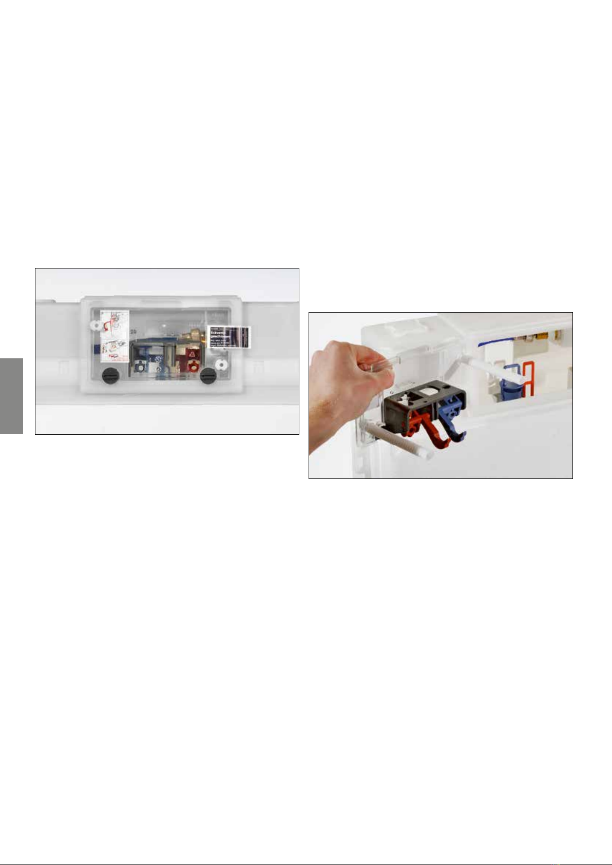
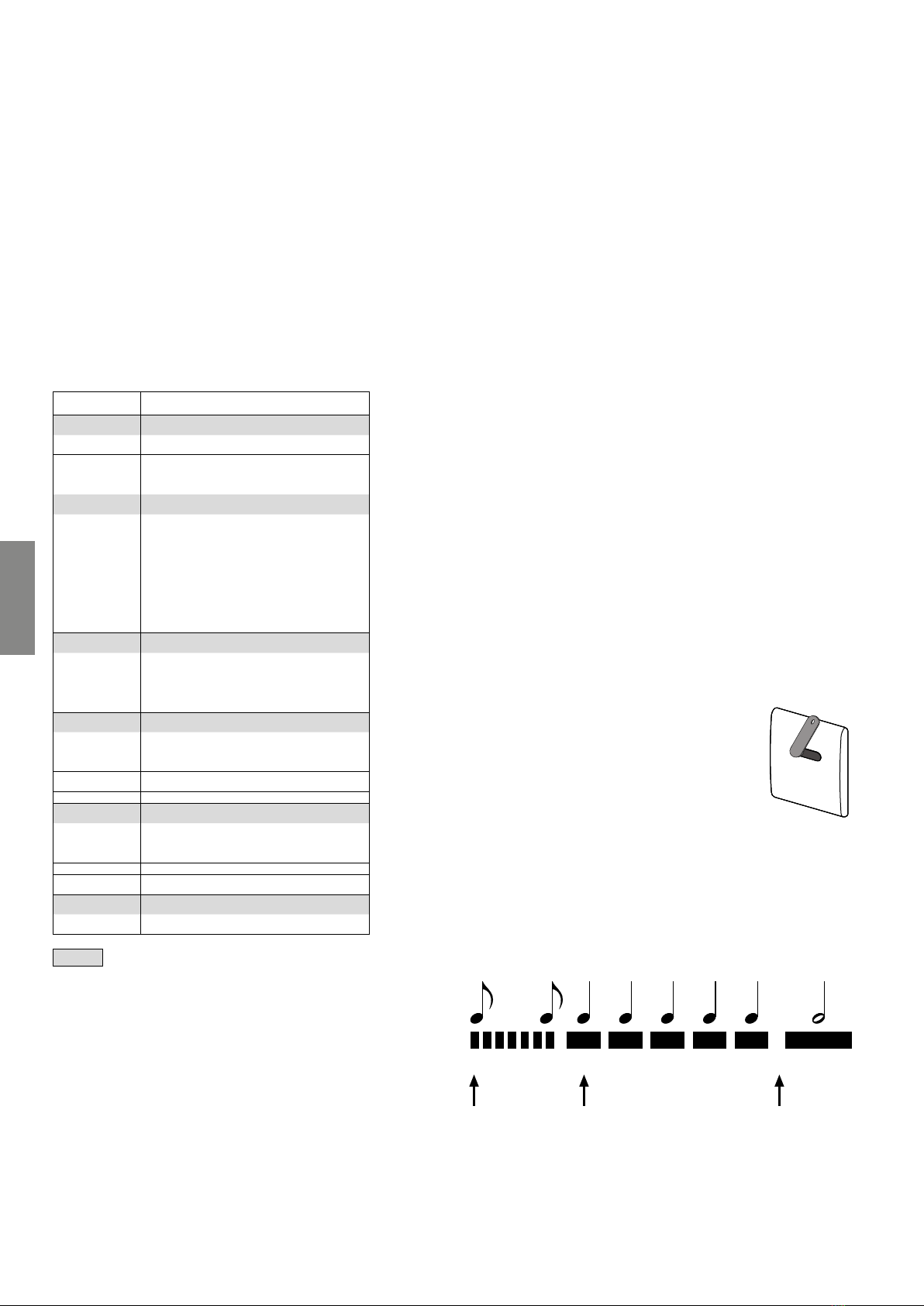
How to program the TECE electronics:
• Hold the programming key briefly
in front of the sensor window. The
programming mode starts with a
quick series of short beeps.
• After the start-up phase, a sequence of the same beeps
can be heard. Count the beeps until you reach your
desired function.
• Now remove the programming key. A long beep indi-
cates that the programming key has been removed.
Example: Setting the flush time to three seconds
. . . .
Hold the programming
keybin front of the
sensor
Remove the key
Start 1 2 3 4 5 OK
Count the individual beeps
until the desired position is
reached
TECE flushing technology – U 1 urinal flush valve

Flushing technology
6-19
Urinal flush plates for the new U 1 urinal flush
valve
TECEsquare II metal
TECEsquare glass
TECEsquare metal
TECEloop plastic
TECEloop glass
TECEplanus
TECEnow
TECEambia
The urinal flush plates shown here only give an overview
of the available product range. See the whole range online
at www.tece.de. All urinal flush plates are shown in this
overview. For more information on TECE push plates, refer
to the “Flush plates” technical guidelines.

Flushing technology
6-20
U 2 TECEfilo urinal flush valve
The new TECEfilo urinal electronics are available with a
metal, glass or plastic surface. Their appearance therefore
harmonises perfectly with various TECE flush plates such
as with theTECEsquare metal, TECEsquare glass toilet
flush plates or with the TECEnowtoilet flush plate. The
TECEfilo urinal electronics with a glass or plastic surface
can also be mounted flush to the surface with the TECEfilo
installation frame.
4
100
150
100
150
7
5
100
150
TECEfilo, metal
TECEfilo, glass
TECEfilo, plastic
Based on a service life of two years, the battery lasts for
• , flushes or
• approx. flushes/day.
The U2 TECE urinal flusher is suitable for installation in dry
and brick-wall constructions. For dry-wall structures, instal-
lation is performed together with the TECE urinal module.
The transformer is already integrated into the two shell
elements which means that it is suitable for direct 230 V
connection.
U2 TECEbox urinal flush valve
housing for brick-wall structure
(9370040)
Compatible with the V mains
and the . V battery variants.
The transformer for V mains
operation is already integrated.
210
80
200
130
min. 83
TECEprofil urinal module with U2
flush valve housing (9320013)
Compatible with the V mains
and the . V battery variants.
The transformer for V mains
operation is already integrated.
min. 75
0 -200
500
1120-13000
max. 1070
500-910
450-770
200-600
OKFF
min. 14
80
130
1153-1333
TECEfilo installation frame for
flush-mounted installation, for
dry-wall constructions only
(9242040/...41/...42)
The TECEfilo plastic electronics,
like the glass ones, can be mount-
ed with the TECEfilo installation
frame for flush-mounted installa-
tion in dry-wall structures.
170
157
110
107
220
160
TECE flushing technology – U 2 TECEfilo urinal flush valve
This manual suits for next models
11
Table of contents
Other TECE Toilet manuals

TECE
TECE one 9700200 User manual

TECE
TECE TECEone User manual

TECE
TECE TECElux 100 9600100 Instruction Manual

TECE
TECE TECEone User manual

TECE
TECE TECEone User manual

TECE
TECE TECEone User manual

TECE
TECE TECEbox 8 cm Instruction Manual

TECE
TECE TECEone Instruction Manual

TECE
TECE TECEplanus Installation manual

TECE
TECE TECEone User manual
Popular Toilet manuals by other brands

IFO
IFO 8710080 manual

NATURE LOO
NATURE LOO CLASSIC 650 Installation and operation manual

Signature Hardware
Signature Hardware CARRAWAY SHCR240S quick start guide

Kohler
Kohler K-3399 Homeowner's guide

Grohe
Grohe 39378SH0 installation manual

Spectrum
Spectrum Pfister Halifax VTP-E10HLW Quick installation guide