manuals.online logo
Brands
  1. Home
  2. •
  3. Brands
  4. •
  5. Roca
  6. •
  7. Toilet
  8. •
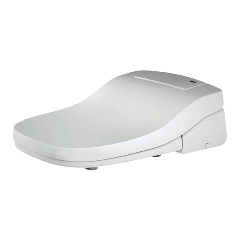
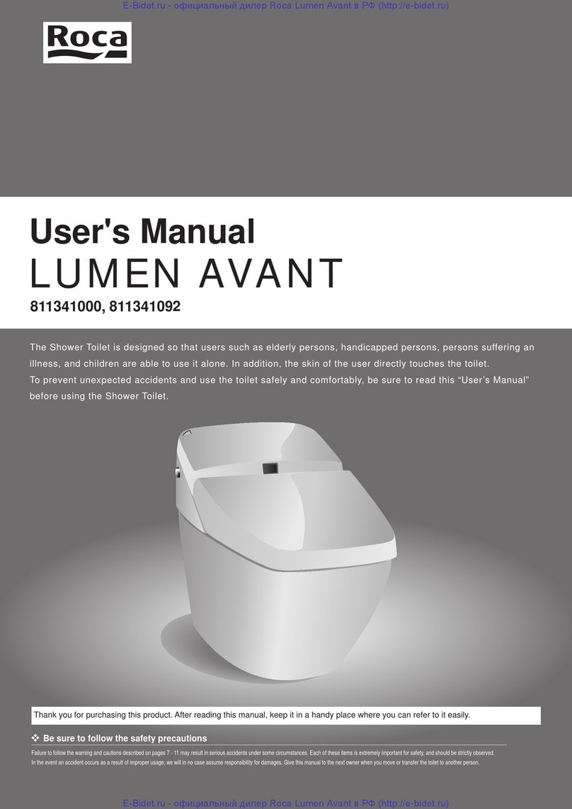
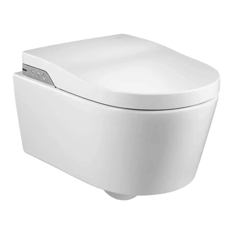
  9. Roca LUMEN AVANT 811341000 User manual

Roca LUMEN AVANT 811341000 User manual

LUMEN AVANT
Installation Manual
PCW-1218A-EU(12010) Thank you for purchasing this product.
●Carefully read this Installation Manual to install
the product correctly.
●Be sure to test operation after installation has
been completed.
●Be sure to pass this Installation Manual,
User’s Manual and Warranty Certificate to
customers. When passing these to customers,
explain the operation method.
CAUTION
Representing product No.
811341000
811341092
Observe Safety Precautions for Safety!
These safety precautions are essential for safe installation and use of the product.
Please read the precautions thoroughly before installing the product.
WARNING
Indicates a potentially
hazardous situation which,
if not avoided, could result
in death or serious injury.
CAUTION
Indicates a potentially hazardous
situation which, if not avoided,
may result in minor or moderate
injury or damage to other property.
Explanation of Hazard Symbols
Checking Power Supply
Follow the instructions below when performing wiring and installing the outlet. Consign wiring work to an electrician.
●Use an outlet with both a grounding terminal and grounding electrode, and suitable for 220–240 VAC with a maximum
rating of 600W. (For a toilet bowl with heater, 34W is added to the maximum rating.)
If the outlet is not equipped with a grounding electrode or grounding terminal, replace it with the required one. In addition,
when using the toilet bowl with a heater or using this product with other electrical appliances, prepare the required number of
outlets.
Be sure to connect the grounding lead of the shower toilet to the grounding terminal.
●Install the outlet in a position as high above the floor as allowed by the length of the cords to avoid exposure to splashing
water. The length of the power cord and grounding lead is 1.0 m.
*
Do not insert the power plug into the outlet until installation is completed. Failure to observe this may cause malfunction of the product.
Water Pressure
●The minimum operation water pressure is 16 L per minute, and at least 0.1 MPa (1.0 kgf/cm2) when flowing. The
maximum water pressure is 0.75 MPa (7.6 kgf/cm2).
When using other appliances simultaneously, water pressure of at least 0.1 MPa (1.0 kgf/cm2) is required. If the minimum
water pressure is less than this value, the ideal washing performance may not be obtained.
Use the special device (CWA-44) to measure the water pressure.
●The above water pressure cannot be obtained if the pipes are 10A or less. Use pipes of 15A (13 mm) or more.
WARNING
Do not allow any anyone except an
authorized service technician to disassemble,
repair or modify this product.
* Electric shock, fire, or injuries may result.
DO NOT
DISASSEMBLE
Connect the grounding lead to the grounding terminal.
* Not connecting this or inappropriate connection
may cause electric shock or fire.
* If the outlet is not equipped with a grounding terminal,
consult an electrician.
GROUND
Do not pour water or cleanser onto the body
or the power plug.
* Electric shock or fire may result. DO NOT WET
Do not install the product in locations subject
to high humidity, such as a bathroom.
* Electric shock or fire may result. DO NOT USE
NEAR WATER
Do not use any loose outlet or an ungrounded
outlet.
* Electric shock or fire may result. PROHIBITED
Do not connect the product to any water
source other than tap water.
* The inside of the product may be corroded,
causing an electric shock, fire or skin inflammation.
PROHIBITED
Do not remove or insert the power plug with
wet hands.
* Electric shock may result. NO WET HANDS
●Do not use the product with any power
supply other than 220–240 VAC.
●Do not plug any other appliances into the
same power outlet.
* Fire may result.
PROHIBITED
Do not nick, damage, carve, bend unduly, pull,
twist or bind the power cord, place any heavy
object on it, or pinch the power cord between
any objects.
*
The power cord may be damaged, causing electric shock or fire.
PROHIBITED
Firmly insert the power plug into the outlet.
* Electric shock or fire may result.
OBSERVE
Install the product correctly according to the
Installation Manual.
* Electric shock, fire, or injuries may result.
*
Water may leak, resulting in water flooding over the floor.
OBSERVE
CAUTION
●When removing the strainers, be sure to
close the water shutoff valve.
●When attaching the strainers, tighten these
completely so that there is no clearance.
* Water may leak, resulting in water flooding over the floor.
OBSERVE
Flush any foreign matter and rust in the pipes
completely before connecting the product.
* Damage inside the product may cause water
leakage, resulting in water flooding over the floor.
OBSERVE
If freezing weather is anticipated before
handing the product to the customer, drain
water and leave it.
* Damage from freezing may cause water leakage,
resulting in water flooding over the floor.
OBSERVE
Be sure to adjust the water shutoff valve and
check for water leakage after installation.
* Water may leak, resulting in water flooding over
the floor.
OBSERVE
Before Mounting Body
Mount the toilet bowl before mounting the body.
Do Not Place Body on Floor!
Never place the body on the floor.
Secure Water Supply Pipe!
Firmly secure the water supply pipe to prevent any looseness.
* Abnormal noise or water leakage may result.
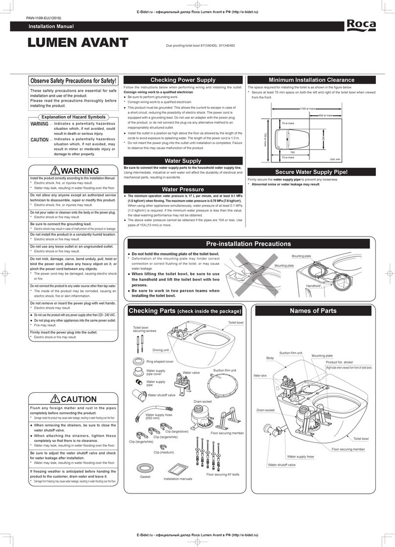
Minimum Installation Clearance
The space required for installing the toilet is as shown in the figure below.
* Secure at least 70 mm space on both the left and right of the
product when viewed from the front.
Be sure to connect the water supply parts to the household water supply line.
Using intermediate, industrial or well water will affect the durability of electrical and mechanical parts, resulting in accidents.
Water Supply
Checking Parts (check inside the package)
Body Decorative
panel (right)
Screws
Bolts
Installation manual
Decorative
panel (left)
Wood screws Plastic anchors
Remote control
Batteries
(2 pcs.)
Bracket
*
The bracket is attached to
the rear of the remote control.
Slide it off to remove it.
Names of Parts
Toilet lid
Body
Top cover
Toilet seat
Water shut off valve
Power plug
(with ground
fault protector)
Open/close handle Water supply hose
Grounding lead
Toilet bowl
Seat sensor
Nozzle (for posterior)
Nozzle (for bidet)
Washer
Anchor Nuts
Instruction manual and
other documents
1190 or more
460
400 or more
700 or more
(mm)
790
70 or more
Top cover
*Attached to the body
70 or more
The new water supply hose supplied with
this product are to be used and old hose-sets
should not be used.
OBSERVE
 
参考 2
Mount the toilet bowl as described in the Installation Manual (PAW-1109-W) included in the product package.
Mounting Toilet Bowl
1
Installation Procedure
Connecting Body to Toilet Bowl
4
Installation diagram
4.Connect the water supply hose.
(1)Insert a water supply connection hose
from the body into the water valve spout. (2)Firmly secure the hose and the
spout with the body connection
clip. (Use the body connection clip
removed in step 󱯒)
(1)
Connect the toilet bowl connectors (one black
connector for water valve; two white connectors
for drive unit) to the body connectors.
(3)Push the body all the way to the
rear.
(3)Engage the tips of the connection
clip to fit the clip, and check that the
clip is attached firmly.
Body
Connector
Toilet bowl
Attach the Anchor Nuts to the toilet bowl.
Attaching Anchor Nuts
2
5.Connect the body to the toilet bowl.
Anchor Nut
Mounting plate
Anchor Nut
Body connection clip
Anchor Nut Anchor Nut
Click
Water valve spout
Water shutoff cap
* Will not be used
Body connection clip
* Will be used later
Water valve ①
②
Bend
Click
Water supply
connection hose
Body connection clip
Water supply
connection hose
1.Check that the water shutoff valve is closed.
2.
Remove the body connection clip and the water shutoff cap.
Preparing to Connect Water
Supply Hose to Water Valve
3Be sure to perform
depressurizing before
removing the body connection
clip and the water shutoff cap.
(See 󱦿in the Installation
Manual contained in the toilet
bowl package.)
Omission of depressurizing
will cause water to splash
when the body connection
clip and water shutoff cap are
moved.
Note 1
Toilet bowl connectorsBody connectors
2.Remove the top cover.
3.Mount the body on the toilet bowl.
Mount the body on the toilet bowl so that the slots on
the rear surface
of the body are
engaged with
the securing
tabs on both
sides of the
mounting plate.
Securing tabs
Slots
Rear surface of body
Engage slots (upper right
figure) with securing tabs
Water valve
Slots
Toilet bowl
Body
Push
(2)Stow the connectors in the left-
side space of the wafer valve.
Attach the clip firmly.
* Incorrect attachment will
cause water leakage.
Note 2
Attach the clip so that the
ends of the clips are engaged
and you hear a click.
* Incorrect attachment will
cause water leakage.
Note 4
Be careful not to damage the
O-ring.
* Water may leak if the O-ring
is broken or damaged.
Note 3
Reference 1
●When removing the clip, hold
the clip with your fingers and
insert a flat-blade screwdriver
as shown in the figure and
push it downward.
Push
See Reference 1
Connector
Water valve
1.Check that the connector is pulled up.
* Otherwise, the body cannot be connected to the
toilet bowl. Connector (white)
Wafer valve
See Note 1
See Note 2 See Note 3 See Note 4
5
7
Connecting Power Supply
Checking Mounting Position and Securing Body
1.Remove the power plug from the outlet.
(4)Adjust the left and right balance of the toilet bowl.
2.Insert the power plug in the receptacle.
4.Check that power is supplied.
Check that the power lamp on the body is lit.
Power plug
Connect the grounding lead
to the grounding terminal.
* Not connecting this or
inappropriate connection may cause
electric shock or fire.
*
If the outlet is not equipped with a
grounding terminal, consult an electrician.
WARNING
GROUND
6Positioning and Mounting Remote Control
Mount the remote control as described in the Instruction Manual included in the remote control package.
Power lamp
●If the power lamp does not
light, press the reset button
on the power plug and
check that the power lamp
lights.
Note 5
Water leakage at the supply/
drain water connecting
sections may not be observed
unless water is flushed
several times.
Note 6 8Checking Water Leakage
3. Check toilet bowl flushing operation.
(1)Prepare seven balls of rolled up 760 mm toilet paper, and put these balls in the toilet bowl.
(2)
Check that these balls are flushed away in a single flushing operation. If not flushed away in a single operation, check the water pressure.
(3)Press the [BODY CLEANING] button on the remote control to lower the body.
Connect the power supply to
confirm the position of the body.
Do not secure the body yet.
1.Fully open the open/close handle of the
water shutoff valve. 2.Check that there is no water leakage.
(1) Operate the remote control to flush the toilet several times.
(2)
Check that there is no water leaking at connecting sections.
Open
Open/close handle
Water shutoff valve Leakage check sections
①
 
Bonding section between water shutoff valve and wall or floor
②
 
Connecting section between water shutoff valve and water supply pipe
③
 
Connecting section between water shutoff valve and water supply hose
④
 
Connecting section between toilet bowl and body
⑤
 
Connecting section between water supply connection hose and water valve
For the bonding section between the water
shutoff valve and wall, lift the ring shaped
cover and the water supply pipe cover to
check that there is no water leakage.
①
③
④
⑤
Ring shaped cover
Water supply pipe cover
②
1.Attach the top cover.
2.Remove the top cover.
5.Attach the top cover.
4.Secure the body.
Align the two bolt holes on both sides at the
rear of the body and the toilet bowl, and use a
screwdriver to tighten the bolts.
Bolt
Bolt hole
Washer
Bolt
Washer
6.Insert the power plug into the outlet.
Top view
Toilet seat Toilet bowl
Toilet bowl Toilet seat
*If water flows into the toilet bowl, check that the
manual lever of the water valve is closed.
3.Check the mounting position.
(1)
Press the [BODY CLEANING] button on the remote control to raise the body.
(2)
Check that the body is completely engaged with the securing tabs on the toilet bowl.
No clearance
between body and
toilet bowl
Body lifting from
toilet bowl (5 mm
or more)
See Reference 2
Reference 2
See Note 5
See Note 6
PCW-1218A-EU(12010)
Checking posterior washing and bidet washing operation
1.Check the posterior washing operation.
(1)
Check that the seat sensor is covered with paper.
(2)Press the [SHOWER] button.
As the nozzle begins spraying, cover the tip of the nozzle with your hand to prevent water from splashing.
* Initially it takes approximately one to two minutes until the tank is full and spraying
is available. (Setting the spray strength to the strongest level shortens this time.)
(3)Press the [STOP] button to stop posterior washing.
* The product is equipped with a seat sensor that
detects you have sit down on the seat. Posterior
washing, bidet washing, and deodorizing are not
activated unless you are sitting on the toilet seat.
If no paper is attached, cover the seat sensor with
whitish paper or cloth.
Test Operation (Follow the steps below to conduct test operation when installation is completed.)
2.Check the bidet washing operation similarly.
(1)Hold down the partial flush button and the toilet seat open/close button
simultaneously for at least 20 seconds. (When the setting has been
changed, a beep sounds.)
Hold down these buttons simultaneously for at least 20 seconds.
(2)
Prepare seven balls of rolled up 760 mm toilet paper, and put these balls
in the toilet bowl. Check that these balls are flushed away in a single
flushing operation.
If the amount of flushing water is restricted as required in some municipalities, the flushing amount can be
changed to 8 L for full flush and 6 L for partial flush according to the steps below.
Attaching Decorative Panel and Top Cover
Top cover
Set here
Tab Tab
Tab Tab
Decorative panel
Screw Screw
(2)
When fitted onto the body, secure the
decorative panel with the three screws.
*Be sure to secure the panel with
screws.
(1)
Fit the decorative panel onto the body so that
the tabs on the decorative panel face the body.
* Be sure to fit the decorative panel so that there is
no step between the panel and the rear cover.
1.Attach the decorative panel. 2.Attach the top cover.
Open the lid, and check the hot water (shower) temperature and toilet
seat temperature.
If the water does not flow well, clean the
strainer.
(3) Remove the top cover.
(2) Operate the open/close handle to
close the water shutoff valve.
(5) Separate the mesh part of the
strainer from the threaded part.
Wash away any dirt inside the
mesh part and from the O-ring.
(6) Attach the strainer to its original
position.
(7) Open the water shutoff valve.
(8) Attach the top cover.
(9) Insert the power plug into the outlet.
*
If the water still does not flow well, check the water supply pressure.
 
If freezing weather is anticipated before handing
the product to the customer, drain the water.
(2) Operate the open/close handle to close
the water shutoff valve.
Do not remove the strainer
with the water shutoff valve
open.
* Water will leak from the
strainer.
Note 8
When attaching the strainers,
tighten them completely so
that there is no clearance.
* Incomplete tightening will
cause water to leak from the
strainer.
Note 9
(4) Remove the strainer from the top
of the body.
Close
Strainer
Strainer
Attach
(3) Remove the top cover.
(7) Remove the water supply hose from
the water shutoff valve, place a wash
bowl or similar, and drain the wafer
from the hose.
(8) Attach the water supply hose to the
water shutoff valve.
(9) Firmly attach the strainer.
(
11
) Attach the top cover.
Water supply hose
Wash bowl
Water shutoff
valve
Clip
Close
Water shutoff valve
(6) Remove the strainer from the top of
the body.
Seat sensor
Strainer
Remove
Flat-blade
screwdriver
Flat-blade
screwdriver
(
10
) Turn the manual lever (red) clockwise.
Manual lever (red)
Turn counterclockwise
Flat-blade
screwdriver Strainer
Remove
(5) Turn the manual lever (red)
counterclockwise 180 degrees.
(4) Drain the water from the hot water tank.
Do not drop the screws into
the toilet bowl.
* The body must be removed.
Note 7
How to drain water from hot
water tank
Press [MASSAGE] and
[NOZZLE POSITION / REAR]

simultaneously for at least two
seconds to drain the water from
the hot water tank.
* It takes approximately 20
seconds until water is drained
completely.
<Remote control>
Hold down these buttons
simultaneously for at least two
seconds.
9
See Note 7
Decorative panel
(1)
Remove the power plug from the outlet.
See Note 8
See Note 9
Water shutoff valve
(1) Remove the power plug from the outlet.
See Note 8
See Reference 3
See Reference 1
Reference 3

This manual suits for next models

1

Other Roca Toilet manuals

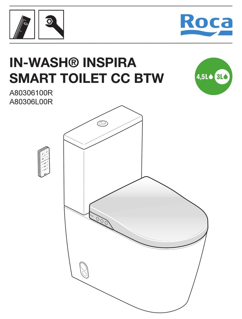
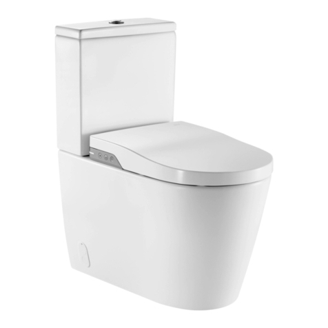
Roca IN-WASH INSPIRA User manual

Roca

Roca IN-WASH INSPIRA User manual

Roca IN-WASH INSPIRA A803060001 User manual

Roca

Roca IN-WASH INSPIRA A803060001 User manual

Roca IN-WASH INSPIRA A803060001 User manual

Roca

Roca IN-WASH INSPIRA A803060001 User manual

Roca IN-WASH INSPIRA User manual

Roca

Roca IN-WASH INSPIRA User manual

Roca DAMA SENSO COMPACT User manual

Roca

Roca DAMA SENSO COMPACT User manual

Roca MULTICLEAN A804001 Series User manual

Roca

Roca MULTICLEAN A804001 Series User manual

Roca UMEN AVANT 811340400 User manual

Roca

Roca UMEN AVANT 811340400 User manual

Roca IN-WASH INSPIRA User manual

Roca

Roca IN-WASH INSPIRA User manual

Roca MULTICLEAN PREMIUM A80400800 User manual

Roca

Roca MULTICLEAN PREMIUM A80400800 User manual

Roca MULTICLEAN PREMIUM A80400600 User manual

Roca

Roca MULTICLEAN PREMIUM A80400600 User manual

Roca INSPIRA WH A803094001 User manual

Roca

Roca INSPIRA WH A803094001 User manual

Roca IN-WASH INSPIRA A803060002 User manual

Roca

Roca IN-WASH INSPIRA A803060002 User manual

Roca IN-WASH INSIGNIA A803104001 User manual

Roca

Roca IN-WASH INSIGNIA A803104001 User manual

Roca IN-WASH INSIGNIA A803104001 User manual

Roca

Roca IN-WASH INSIGNIA A803104001 User manual

Roca IN-WASH INSPIRA SMART CC BTW A80306100R User manual

Roca

Roca IN-WASH INSPIRA SMART CC BTW A80306100R User manual

Roca MULTICLEAN A804006009 User manual

Roca

Roca MULTICLEAN A804006009 User manual

Roca IN-WASH INSPIRA A803061001 User manual

Roca

Roca IN-WASH INSPIRA A803061001 User manual

Roca LUMEN User manual

Roca

Roca LUMEN User manual

Roca 9505388 User manual

Roca

Roca 9505388 User manual

Roca MULTICLEAN PREMIUM A80400700 User manual

Roca

Roca MULTICLEAN PREMIUM A80400700 User manual

Roca MULTICLEAN PREMIUM A80400600 User manual

Roca

Roca MULTICLEAN PREMIUM A80400600 User manual

Roca IN-WASH INSPIRA A803063001 User manual

Roca

Roca IN-WASH INSPIRA A803063001 User manual

Roca IN-WASH INSPIRA A803061002 User manual

Roca

Roca IN-WASH INSPIRA A803061002 User manual

Roca IN-WASH INSPIRA User manual

Roca

Roca IN-WASH INSPIRA User manual

Popular Toilet manuals by other brands

Kohler K-3422 installation guide

Kohler

Kohler K-3422 installation guide

Cinderella Motion installation manual

Cinderella

Cinderella Motion installation manual

BEMIS NextStep installation instructions

BEMIS

BEMIS NextStep installation instructions

Kohler K-3466 Homeowner's guide

Kohler

Kohler K-3466 Homeowner's guide

Woodbridge LT611 installation manual

Woodbridge

Woodbridge LT611 installation manual

Reece Roca installation instructions

Reece

Reece Roca installation instructions

American Standard ACTICLEAN 7381737-400.0070A Assembly

American Standard

American Standard ACTICLEAN 7381737-400.0070A Assembly

Akw 28403 Installation & user guide

Akw

Akw 28403 Installation & user guide

Danze Orrington DC013330 installation instructions

Danze

Danze Orrington DC013330 installation instructions

BEMIS bioBidet BB800 owner's manual

BEMIS

BEMIS bioBidet BB800 owner's manual

Dudley Resan Fitting instructions

Dudley

Dudley Resan Fitting instructions

Kohler SAN RAPHAEL GRANDE K-8688T-TPF installation instructions

Kohler

Kohler SAN RAPHAEL GRANDE K-8688T-TPF installation instructions

SFA-SANIFLO SANIGRIND Installation and maintenance instructions

SFA-SANIFLO

SFA-SANIFLO SANIGRIND Installation and maintenance instructions

Kohler BANCROFT K-3827T installation instructions

Kohler

Kohler BANCROFT K-3827T installation instructions

Kohler K-3900X-2 installation guide

Kohler

Kohler K-3900X-2 installation guide

Toto MS654114MF01 Installation and owner's manual

Toto

Toto MS654114MF01 Installation and owner's manual

Separett FLAME 8000 manual

Separett

Separett FLAME 8000 manual

DURAVIT SensoWash Slim operating instructions

DURAVIT

DURAVIT SensoWash Slim operating instructions

manuals.online logo
manuals.online logoBrands
  • About & Mission
  • Contact us
  • Privacy Policy
  • Terms and Conditions

Copyright 2025 Manuals.Online. All Rights Reserved.