Topmodel Ecotop G103C TWIN III ACRO User manual
Order N° 066G103
ATTENTION !
Ce modèle à construire n’est pas un jouet, il
ne convient pas aux enfants de moins de 14 ans.
Une mauvaise utilisation de ce matériel peut
provoquer des dommages matériels ou corporels.
Vous êtes pleinement responsable
lorsque vous utilisez votre modèle.
Volez à une distance de sécurité des zones
habitées.
Soyez sûr que personne n’émet sur la même
fréquence que vous.
CAUTION !
This model construction kit is not a toy and is not
suitable for children under the age of 14.
Incorrect use of this material could cause material
damage ou personal injury.
You are fully responsible for your actions when you
use this model.
Fly at a safe distance from occupied zones.
Be sure that no one else is using the same
frequency as you.
Distribué par / Distributed by:
TOPMODEL S.A.S.
Le jardin d’entreprises de SOLOGNE - F-41300 SELLES SAINT DENIS - www.topmodel.fr
©TOPMODEL 2010
Planeur semi-maquette
Semi-scale sailplane
Caractéristiques techniques/Technical data:
Echelle/scale: 1:6,5
Envergure/wingspan: 2,77m
Longueur/length: 1,25m
Poids/TO weight: 2,4/2,5kg
Surface/wing area: 41,4dm2
Profil/airfoil: MH32 mod.
Equipements recommandés/Recommended equipments:
Moteur/motor: XPower XC3223/10LS
Contrôleur/ESC: XPower XREG60
Accu/battery pack: XPower Xtreme11,1V 2600mAh (3S)
Hélice/prop: XPower FOLDING PROP 13x6” #099FB1306
Porte pales/prop hub: XPower 20mm +5° #099H200805
Radio/RC set: Récepteur/receiver: XPower RP8D1
Ailerons: 2 servos TOPMODEL SS1816
Profondeur/Elevator: 1 servo TOPMODEL SS1816
Direction/Rudder: 1 servo TOPMODEL MS2414
AF/AB: AF ELECTRIQUE/ELECTRIC SPOILER 250mm #099ELAF25
Distribué par / Distributed by:
p
/
y
TOPMODEL
S.A.S.
L

MERCI
d’avoir choisi le planeur semi-maquette GROB G103C TWIN III ACRO ECOTOP!
Nous avons fait un grand effort en dessinant et construisant ce planeur pour qu’il soit le meilleur modèle que vous ayez jamais construit et fait voler.
Nous vous fournissons un kit avec la plus haute qualité et les meilleures performances possibles.
Nous vous souhaitons un grand succès en assemblant et en faisant évoluer votre nouveau
GROB G103C TWIN III ACRO ECOTOP.
IMPORTANT:Merci de bien vouloir lire et étudier cette notice de montage avant de commencer l’assemblage. Faire l’inventaire des pièces à l’aide de la nomenclature
pour contrôler qu’il n’y a pas de manquant ou d’imperfection.
Merci de contacter immédiatement TOPMODEL si vous constatez une pièce manquante ou une pièce endommagée.
GARANTIE: Il est important de notifier à TOPMODEL tous dommages ou problèmes avec ce modèle dans les 7 jours suivant la réception du kit pour bénéficier de la
garantie. En cas de retour du modèle, le client est responsable du transport et le port retour est à sa charge. En cas de défaut, la pièce sera échangée ou remplacée une
fois que celle-ci sera réceptionnée par TOPMODEL pour expertise (transport à la charge du propriétaire). En cas de problème, n’hésitez pas à contacter TOPMODEL.
TOPMODEL ne peut pas contrôler la dextérité du modéliste et ne peut pas influencer le constructeur durant l’assemblage ou l’utilisation de ce modèle radio-commandé.
Aussi, nous ne pouvons, en aucun cas, être tenus responsables des dégâts matériels, accidents corporels ou décès pouvant être causés par ce modèle réduit.
L’acheteur/utilisateur accepte toutes les responsabilités en cas de problèmes structurels ou mécaniques.
2
RETENDRE L’ENTOILAGE
1) Déballez doucement en prenant soin de ne pas endommager une
partie du kit. Déballez toutes les pièces de leur emballage plastique pour
inspection.
Avant de commencer tout montage ou de poser tout auto-collant, il
est très important de retendre l’entoilage déjà appliqué. A cause du
transport, de la chaleur et de l’humidité qui varient beaucoup suivant les
différents climats, l’entoilage peut se détendre et se “rider” au soleil. Si
vous prenez le temps de retendre l’entoilage, vous serez récompensé par
un modèle qui restera magnifique dans le temps.
2) En utilisant un fer à soler et un chiffon doux, “repassez” délicatement
et “suivez” en appliquant le film avec le chiffon. Si des bulles apparaissent,
votre fer est peut être trop chaud. Réduire la température et travaillez
doucement et patiemment.
3) Si les bulles persistent, piquer les bulles à l’aide d’une aiguille pour
évacuer l’air emprisonné et chauffer de nouveau.
4) Utilisez le décapeur thermique avec beaucoup de précaution. Faire
attention de ne pas chauffer au même endroit trop longtemps. Cela
pourrait trop rétracter les bords et laisser un espace découvrant le bois
aux jointures des différentes couleurs. Les filets sont particulièrement
vulnérables à la surchauffe.
5) Votre modèle est entoilé avec de l’Oracover® blanc N°10.
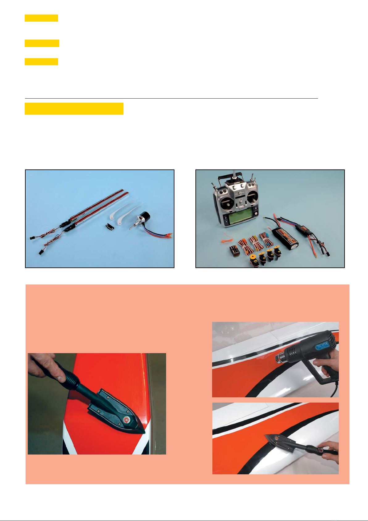
■ MOTEUR
-Moteur brushless XPower XC3223/10LS
-Porte -pales
-Pales d’hélice repliables
-AF électriques 250mm
POUR ASSEMBLER CE KIT
Pour assembler ce kit, vous aurez besoin des produits énumérés ci-dessous:
■ COLLES: Cyano fluide et épaisse, époxy 30mn et 5mn, colle silicone.
■ OUTILS: Couteau de modéliste, tournevis cruciforme (petit et moyen), pince à bec fin, pince coupante, ciseaux, ruban adhésif, ruban adhésif de
masquage, ruban adhésif double-faces, perçeuse (foret Ø0,6-1,8-3 et 3,5mm), papier verre, règle, feutre, clips, alcool, fer à souder, chiffon.
■ RADIO
-Ensemble radio (9 voies mini avec 4
servos et un contrôleur)
-Micro servo x3, mini servo x1
-Rallonge servo
(700mm x2, 800mm x1)
-Contrôleur
-Accu de propulsion LiPo
THANK YOU for your purchase of the ECOTOP semi-scale sailplane GROB G103C TWIN III ACRO ARF!
We made a main effort while drawing and building this sailplane so that it is the best model one than you ever built and fly.
We provide you a kit with the highest quality and the best possible performances.
We wish you a great success while assembling and flying your new ECOTOP GROB G103C TWIN III ACRO.
IMPORTANT: Please take a few moments to read this instruction manual before beginning assembly. Do an inventory of the parts using the parts list, to control that
there is no lack or imperfection. Thank you to contact TOPMODEL immediately, if you note a missing part or a damaged part.
WARRANTY: It is important to notify to TOPMODEL all damage or problems with this model within 7 days following the reception of the kit to be able to benefit the
warranty. In the event of return of the model, the customer is responsible for transport and return shipping cost is at his expenses. In the event of defect, the part will be
exchanged or replaced once this one will be delivered to TOPMODEL for expertise (transport on your cost). In the event of problem, do not hesitate to contact TOPMODEL.
TOPMODEL cannot control the dexterity of the modeler and cannot influence the builder during the assembly or the use of this radiocontrolled model, thus TOPMODEL will in
no way accept or assume responsability or liability for damages resulting from the use of this user assembled product.
The purchaser/user accepts all the responsibilities in the event of structural or mechanical problems.
3
RE-SHRINKING THE COVERING
1) Open you kit slowly and take care not to damage any parts of the kit.
Remove all parts from their plastic protective bags for inspection. Before
doing any assembly or installation of any decals, it is very important to
re-shrink or re-tighten the already applied covering. Due to the shipping
process, heat and humidity changes from different climates, the covering
may become lose and wrinkle in the sun. If you take the time to re-tighten
the covering, you’ll be rewarded with a long lasting beautifully covered
model.
2) Using your covering iron with a soft sock, gently apply pressure and rub
in the covering. If any bubbles occur, your iron may be too hot.
Reduce heat and work slowly.
3) If bubbles persist, use a small pin to punch holes in the bubble to
relieve trapped air and reheat.
4) Use your heat gun with extreme caution. Take care not to apply too
much heat to one area for long periods of time. This may cause the trim
colors to over shrink and pull away leaving sightly gaps on the color lines.
The trim stripes are especially vulnerable to over shrinking.
5) Your model is covered with Oracover® white #10
■ MOTOR
-XPower brushless motor XC3223/10LS
-Propeller hub
-Folding propeller
-Electric spoilers 250mm
TO ASSEMBLE THIS KIT
To assemble this kit, you’ll need the items listed below:
■ ADHESIVE: Cyanoacrylate thin and thick, epoxy 30 and 5min, silicon adhesive.
■ TOOLS: Knife (X-acto), Phillips screw driver (small and medium), needle tip pliers, pliers, scissors, scotch tape, masking tape, double sticking
tape, drill (with 0,6-1,8-3 and 3,5mm bits), sanding paper, ruler, ball point pen, clips, alcohol, soldering iron, piece of cloth or rags.
■ RADIO
-Radio set (more than 9 channels
with servos and ESC)
-Micro servo x3, mini servo x1
-Servo extension
(700mm x2, 800mm x1)
-Electric Speed Controller
-LiPo battery

3
2
68-1 8-1
7
4
3-4
4-8
3-8
2-4
2-8
4-5
4-5 24
4-5
2AF
2AF
3-5
24T
2-5
4C
7
2-41
2
1
2-22-23
1-1
10
6-2
551
AT
551
5516C
6S
5
CONTENU DU KIT KIT CONTENT
N° pièce Désignation Matériau, dimensions (mm) Qté
0 notice de montage manuel A4 01
1 fuselage fibre de verre 01
1-1 couple moteur CTP 3mm + vis M3x10mm + écrou prisonnier M3 02+04+04
1-2 platine radio CTP 3mm 01
2 aile polystyrène coffré-entoilé 02
2-2 fixation aile tige filetée M4 + écrou papillon + rondelle CTP 3mm 02+02+02
2-4 set fixation servos ailerons renfort balsa 1,5mm + set platine servo CTP 2mm
+ vis à bois 2,3x6mm
02+02
+04
2-41A carénage servo aileron plastique moulé 01 set
2-5 tringlerie aileron CAP filetée un bout M2 L=100mm + chape + écrou 02+02+02
2-8 guignol aileron aluminium 02
2-23 saumon fibre verre 02
24 clé d’aile jonc acier 01
24T téton d’aile CAP Ø4 L=30mm 02
2AF chapeau d’AF plastique 02
3 empennage horizontal polystyrène coffré-entoilé 01
3-4 vis fixation stab. vis M3x25mm 02
3-5 tringlerie de profondeur CAP filetée un bout M2 L=100mm + chape + écrou 01+01+01
3-8 guignol de profondeur laiton 01
4 volet de direction balsa entoilé 01
4-5 tringlerie direction CAP filetée un bout M2 L=100mm + chape + écrou
+ CAP L=250mm + tourillon bois dur Ø8 L=600m
01+01+01
+01+01
4-8 guignol de direction aluminium 01
4C charnière plastique type bâton 03
6 set cabine plastique moulé + fibre de verre 01
6-2 set fixation cabine tourillon métal + support CTP 2mm+ verrou
+ support CTP 2mm+ vis à bois 2x6mm
01+01+01
+01+01
6C aménagement cockpit plastique moulé 01
6S siège avant plastique moulé 01
7 décoration planche autocollante 01
8-1 roue Ø60mm + Ø40mm 01+01
10 train d’atterrissage set couples train principal + rondelle CTP + axe métal
+ set couples roue avant + rondelle CTP + axe métal
01+04+01
+01+02+01
551 tableau de bord set tableau de bord “champignon”
+ planche de bord plastique
01
+02
AT appui-tête mousse 02
Part # Item Material, dimensions (mm) Qty
0 building instructions A4 booklet 01
1 fuselage pod fiberglass 01
1-1 motor mount plywood 3mm + screw M3x10 + blind nut M3 02+04+04
1-2 servo tray plywood 3mm 01
2 wing balsa sheeted foam core- covered 02
2-2 wing fixing threaded rod M4 + ear nut + plywod 3mm washer 02+02+02
2-4 ailerons servos fixing set servo mount reinforcement balsa 1,5mm + servo
mount plywood 2mm + self tapping screw 2,3x6mm
02+02
+04
2-41A aileron servo cover molded plastic 01 set
2-5 aileron and flap linkage music wire threaded one end M2 L=100mm + clevis + nut 02+02+02
2-8 aileron control horn aluminium 02
2-23 tip fiberglass 02
24 wing joiner steel rod 01
24T incidence pin music wire Ø4 L=30mm 02
2AF spoiler cover plastic 02
3 horizontal tail balsa sheeted foam core- covered 01
3-4 horizontal tail fixing screw M3x25mm 02
3-5 elevator linkage music wire threaded one end M2 L=100mm + clevis + nut 01+01+01
3-8 elevator horn brass 01
4 rudder balsa covered 01
4-5 rudder linkage music wire threaded one end M2 L=100mm + clevis + nut
+music wire L=250mm + Ø8 dowel pushrod L=600mm
01+01+01
+01+01
4-8 rudder horn aluminium 01
4C hinge plastic pin type 03
6 cabin set vacumed plastic + fiberglass 01
6-2 cabin fixing set metal dowel +plywood 2mm mount + latch
+ plywood 2mm mount + self tapping screw 2x6mm
01+01+01
+01+01
6C cockpit vacumed plastic 01
6S front seat vacumed plastic 01
7 art work sticker sheet 01
8-1 wheel Ø60mm + Ø40mm 01+01
10 landing gear main gear formers set + plywood washer + axle
+ nose gear formers set + plywood washer + axle
01+04+01
+01+02+01
551 instrument panel “mushrom” instrument console set
+instrument board
01
+02
AT head rest foam 02
5

6
Rassembler les pièces ci-contre pour réaliser la tringlerie des ailerons.
Gathered parts for aileron linkage
1) Découper soigneusement l’entoilage au niveau du puit de servo
d’aileron.
Carefully cut out the film covering the servo room
in the wing.
2) Coller au fond du puit, le renfort 2-4 en balsa 1,5mm à l’époxy 5mn.
Secure servo room reinforcement 2-4 to the bot-
tom of servo room with 5’ epoxy.
2) Utiliser une rallonge de 700mm pour le servo et sécuriser la connec-
tion avec du ruban adhésif ou de la gaine thermo. Passer le le câble
dans l’aile à l’aide la cordelette dèjà passée dans l’aile.
Use a 700mm extension cord for the servo and se-
cure the connection with tape or heat shrink tube.
Thread the cord through the wing with string
already routed into the wing.
2) Construire le support servo 2-4 comme sur la photo, coller les
pièces entre-elles à la cyano. Monter le servo sur le support terminé
avec les 2 vis à bois 2-4 de 2,3x6mm.
Construct servo mount 2-4 as photo, secure parts
together with cyano glue. Secure servo completed
mount with 2.3x6mm self tapping screws 2-4.
INSTALLATION TRINGLERIE AILERONS/ AILERONS LINKAGE INSTALLATION
2-4
2-4
2-4
2-4
2-4
2-4
2-4
2-5
2-8
2-41A
2-4
2-4

7
5) Immobiliser le volet d’aileron au neutre avec du ruban adhésif. Déca-
ler le palonnier du servo pour obtenir 90° de course. Couper la partie
non nécessaire du palonnier du servo.
Maintain the aileron to neutral position with
paper tape. Off-set the servo arm one notch to give
90° stroke. The unnecessary part of the servo
arm part is cut out
6) Positionner le guignol 2-8 sur l’aileron et faire un trou de 4mm dans
l’aileron (sans déboucher à l’extrados!).
Locate the control horn 2-8 on the ailerons and
make 4mm hole in the aileron.
7) Coller le guignol à l’époxy 5mn dans l’aileron.
Glue the control horn 2-8 on the aileron with 5’
epoxy glue.
8) Après installation du guignol, visser l’écrou M2 sur la tringlerie 2-5
puis visser la chape. Aileron et servo au neutre, repérer la longueur de
la tringlerie.
After the control horn is installed, put the 2mm
nut on the pushrod and attach the clevis to push-
rod. Whith the aileron and servo in neutral posi-
tion, mark the pushrod for control horn attach-
ment.
9) Faire une baïonnette sur le repère que vous venez de tracer.
Installer la tringlerie comme sur la photo.
Make a Z type bend on the mark. Install the ai-
leron linkage as photo.
10) Repérer la position du support servo dans l’aile.
Temporarily attach the aileron servo mount to the
main wing.
11) Le servo est démonté puis le support servo 2-4 est collé solide-
ment à l’époxy 5mn dans l’aile.
The servo is removed, and the servo mount 2-4 is
bonded to the main wing firmly with 5’ epoxy glue.
12) Découper avec un cutter ou avec une paire de ciseaux, le carénage
de servo d’aileron 2-41A en suivant les lignes. Fixer le carénage sur le
dessous de l’aile avec du scotch double-faces (non inclus).
Cut the plastic aileron servo cover 2-41A with a
knife or scissors according to the lines. Attach
the aileron servo cover on the wing bottom with
double sided tape (not included).
INSTALLATION TRINGLERIE AILERONS/ AILERONS LINKAGE INSTALLATION
2-8
2-5
2-5
2-5
2-5
2-4
2-41A
2-8
5mm
8
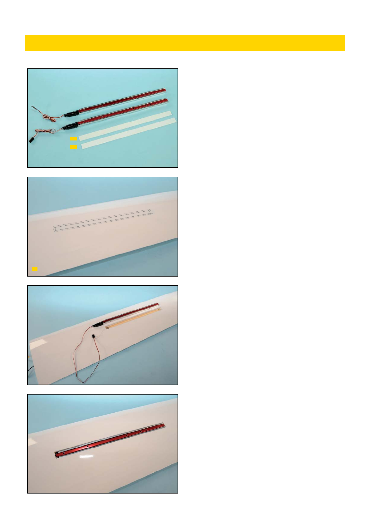
Rassembler les pièces ci-contre pour réaliser l’installation des
aérofreins électriques 250mm XPower.
Gathered parts for XPower 250mm electric air-
brakes installation.
1) Découper minutieusement le film d’entoilage qui recouvre la
réservation pour l’installation de l’aérofrein en laissant un retour de 3 à
5mm que vous collerez dans le puit d’AF avec le fer à entoiler.
Carefully cut out the film covering the airbrake
installation room, leaving 3 to 5mm fringe in
spoiler room and fix in place with iron.
2) Attacher le cable de l’aérofrein à la cordelette puis le passer dans
l’aile 2. L’aérofrein est installé dans son puit une fois que le câble est
passé dans l’aile.
Tie the lead wire of the electric airbrake with
string and pass it through main wing 2. The air-
brake is installed in the main wing while passing
the lead wire in the main wing.
3) L’aérofrein correctement installé doit être comme sur la photo.
Installed properly airbrake should like photo.
INSTALLATION AEROFREINS/ AIRBRAKES INSTALLATION
2AF
2AF
#ELAF25 non fournis/not included
2
9
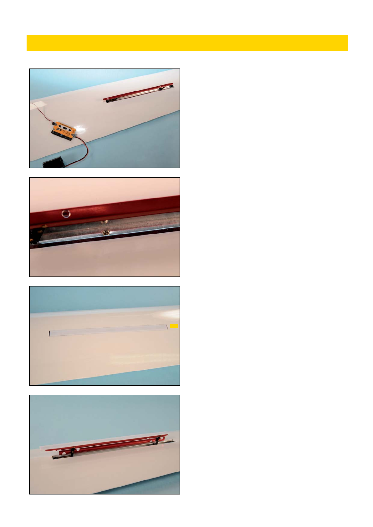
4) Connecter l’aérofrein au SERVO TESTER pour contrôler le bon
fonctionnement.
Connect the airbrake to SERVO TESTER and bat-
tery to check movement.
5) Sortir l’aérofrein et le fixer en place avec des vis à bois 2x5mm (non
fournies) vissées dans les trous existants dans le fond du boîtier de
l’AF.
Extend the airbrake and fix in place with 2x5mm
self tapping screws (not included) installed in the
pre-existing holes at the botton of the airbrake
case.
6) Après fixation de l’AF, ajuster la taille du chapeau d’aérofrein 2AF
pour qu’il s’adapte parfaitement au-dessus de la réservation de l’AF.
After airbrake is installed, adjust the size of the
airbrake cover 2AF to fit perfectly over the air-
brake room.
7) Le chapeau d’aérofrein 2AF est collé sur l’AF avec du scotch double-
faces (pas inclus dans le kit).
The airbrake cover 2AF is secured on the airbrake
with a double-faced tape (not include in the kit).
INSTALLATION AEROFREINS/ AIRBRAKES INSTALLATION
2AF
10
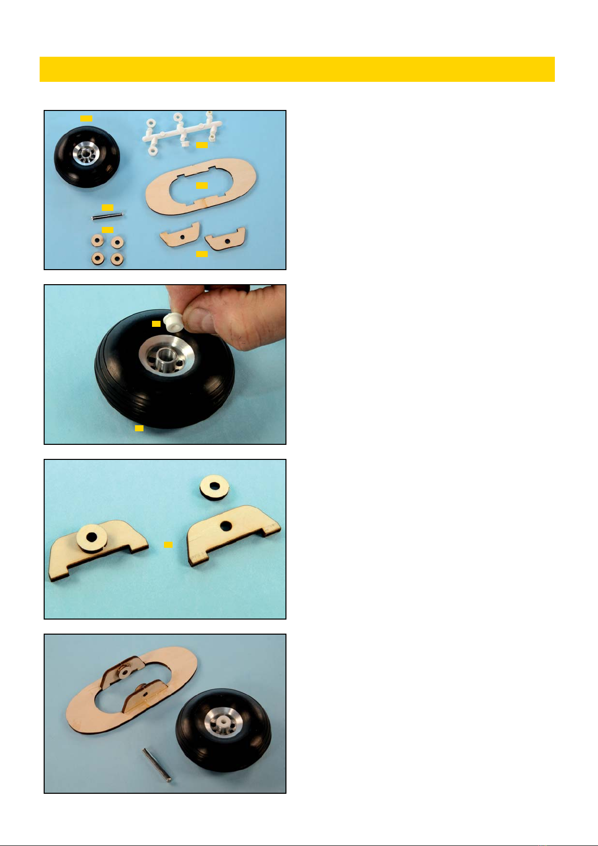
Rassembler les pièces ci-contre pour réaliser l’installation du train
principal.
Gathered parts for main gear installation.
1) Sélectionner l’insert 10 adapté pour l’axe de roue et l’introduire
dans le moyeu de roue. Le poncer si nécessaire pour un ajustage
parfait.
Select a suitable spacer 10 for the axle size and
insert it in the wheel as shown. Sand spacer if
necessary for a perfect fit.
2) La rondelle entretoise en CTP 3mm est collée sur le couple du train
principal 10 comme montré.
The spacer of 3mm plywood is bonded to the main
gear mount 10 as shown.
3) L’ensemble supportant la roue principale est assemblé comme sur la
photo (utiliser de la colle époxy 30mn).
The main gear mount is assembled as shown in
the photo (use 30’ epoxy glue).
INSTALLATION TRAIN PRINCIPAL/ MAIN GEAR INSTALLATION
8-1
10
10
10
10
10
8-1
10
10

11
4) Le pneu est installé en passant l’axe à travers les trous des couples.
Contrôler que la roue tourne librement, élargir le trou de l’insert
plastique si besoin.
The tire is installed by passing the axle through
the holes in mount. Check the movement of wheel,
wheter it turns freely, widen plastic spacer axle if
needed.
6) Essayer à blanc le train principal dans le fuselage et contrôler que la
roue tourne librement.
Trial fit the main gear in the fuselage and check
the movement of wheel.
7) La roue doit sortir du fuselage comme montré sur la photo. Poncer
et ajuster les pièces en CTP si nécessaire
The wheel should extend out of the fuselage as
shown in the photo. Sand and adjust the plywood
mount if necessary.
7) Le train principal est fixé dans la cellule avec de la colle époxy. Il est
bien de renforcer ce collage. Merci d’utiliser du tissu fibre de verre, etc.
(non inclus dans le kit).
The main gear mount is secured to the body with
epoxy adhesive. It is best to reinforce mount in
body. Please, use fiberglass cloth, etc.
(not included in the kit).
INSTALLATION TRAIN PRINCIPAL/ MAIN GEAR INSTALLATION
Fixer l’axe à l’époxy
Fix axle with epoxy
Tissu fibre de verre
Fiberglass cloth

12
Rassembler les pièces ci-contre pour réaliser l’installation du train
principal.
Gathered parts for main gear installation.
1) Sélectionner l’insert 10 adapté pour l’axe de roue et l’introduire
dans le moyeu de roue. Le poncer si nécessaire pour un ajustage
parfait.
Select a suitable spacer 10 for the axle size and
insert it in the wheel as shown. Sand spacer if
necessary for a perfect fit.
2) L’ensemble supportant la roue avant est assemblé comme sur la
photo (utiliser de la colle époxy 30mn).
The nose gear mount is assembled as shown in the
photo (use 30’ epoxy glue).
3) Faire un large congé d’époxy au niveau de la rondelle entretoise CTP
comme sur la photo.
Use a generous amount of epoxy on the plywood
spacer of mount as shown.
4) Le pneu est installé en passant l’axe à travers les trous des couples.
Contrôler que la roue tourne librement, élargir le trou de l’insert
plastique si besoin.
The tire is installed in mount with the axle. At this
time, check whether wheel turns freely.
5) Fixer l’axe en place avec un généreux congé de colle époxy appliqué
sur le couple comme montré.
Fix axle in place wit a generous amount of epoxy
applied to plywood mount and axle as shown.
INSTALLATION TRAIN AVANT/ NOSE GEAR INSTALLATION
8-1
10
10
10
10
10
10
Coller l’axe à l’époxy
Fix axle with epoxy
Coller à l’époxy
Fix with epoxy

13
6) Les cales CTP 3mm (forme en U) sont collées sur le bâti comme
montré. Poncer les extrémités en diagonale en fonction de la forme du
fuselage.
The spacer of 3mm plywood (U-shaped) is bonded
to the mount as shown. Sand edges down diago-
nally according to in the body.
7) Essayer à blanc le train avant dans le fuselage et contrôler que la
roue tourne librement.
Trial fit the wheel in the body as shown and check
the movement of the wheel.
8) La roue doit sortir du fuselage comme montré sur la photo. Poncer
et ajuster les pièces en CTP si nécessaire
The wheel should extend out of the fuselage as
shown in the photo. Sand and adjust the plywood
mount if necessary.
9) Le train avant est fixé dans la cellule avec de la colle époxy. Il est
recommandé de renforcer ce collage. Merci d’utiliser du tissu fibre de
verre, etc. (non inclus dans le kit).
The main gear mount is secured to the body with
epoxy adhesive. It is best to reinforce mount in
body. Please, use fiberglass cloth, etc.
(not included in the kit).
INSTALLATION TRAIN AVANT/ NOSE GEAR INSTALLATION
Fixer l’axe à l’époxy
Fix axle with epoxy
Tissu fibre de verre
Fiberglass cloth
14
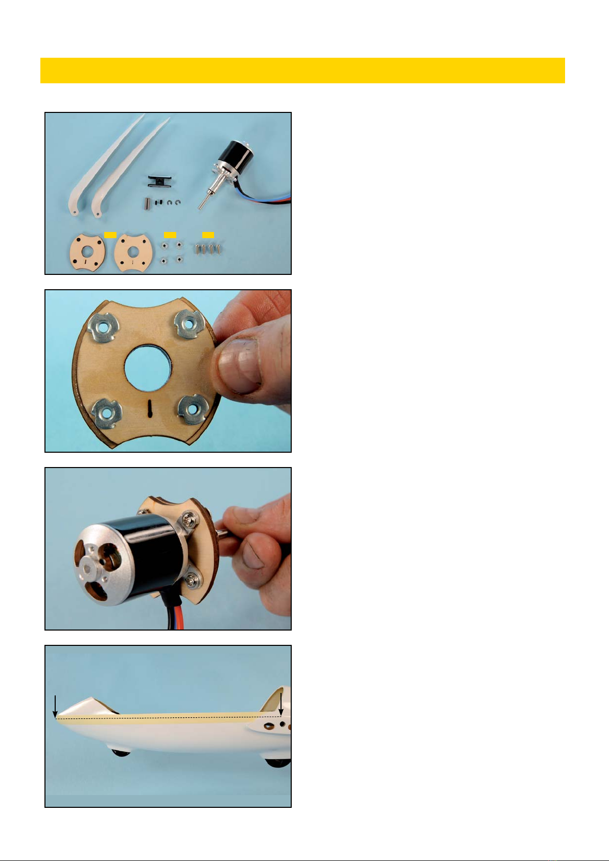
Rassembler les pièces ci-contre pour réaliser l’installation du moteur et
de l’hélice repliable.
Le moteur brushless XPower XC3223/10LS, le porte-pale XPower
20mm +5° et les pales d’hélice repliable XPower 13x6 ne sont pas
inclus dans le kit.
Gathered parts for motor and folding propeller
installation.
XPower XC3223/10LS brushless motor, XPower
20mm +5° hub, 13x6 prop blades are not included
in the kit.
1) Coller les deux couples moteur 1-1 ensembles. Fixer solidement les
écrous prisonniers dans le plus petit couple comme montré.
Bond the two motor mount 1-1 pieces together.
Firmly install the blind nuts in the smaller wood
piece as shown.
2) Le moteur est vissé sur le couple moteur avec les vis M3x10mm.
-La flèche gravée montre le bas du fuselage.
The motor is installed in the mount with 3x10mm
machine screws 1-1.
-The engraved arrow of the mount is positionned
under the body
3) Appliquer un ruban adhésif papier sur le fuselage et tracer une
droite reliant le nez à la partie la plus haute du karman d’aile. Cette
droite matérialise la ligne de référence pour l’installation du moteur.
Merci d’installer le moteur parallèle à cette droite.
Apply masking tape to the side of the fuselage and
draw a line from the nose to the upper surface of
the wing. This line is the reference line of the mo-
tor installation.
Please, install the motor parallel to the line.
INSTALLATION MOTEUR/ MOTOR INSTALLATION
1-1 1-1 1-1
#099FB1306
#099H200805
#099C322310LS
15
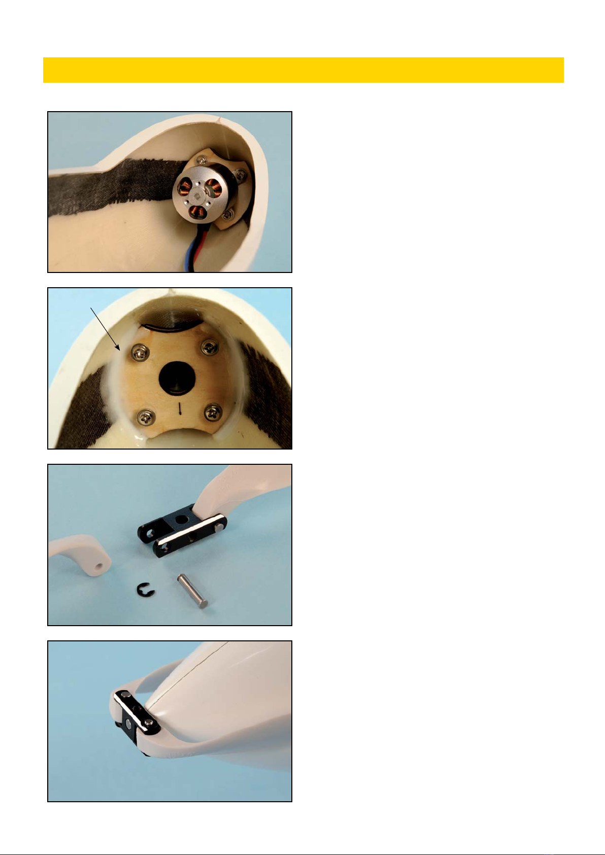
4) Quand la position est déterminée, pointer le couple moteur à la
cyano.
When the position is determined, fix mount in
nose with cyanoacrylate.
5) Renforcer le collage du couple avec un généreux congé d’époxy
30mn autour du couple.
-Notez la position de la flèche gravée dans le couple.
Reinforce mount attachment with a generous
amount of 30’epoxy glue around mount and body
gap.
-Note location of arrow engraved on the mount.
6) Monter les pales d’hélice sur le porte-pales comme sur la photo.
Assemble folding prop on the hub as photo.
7) Monter l’ensemble hélice repliable sur l’arbre moteur en vissant
fermement le set de vis de 3mm.
Secure folding propeller on the motor shaft by
tightening the 3mm set screw firmly.
INSTALLATION MOTEUR/ MOTOR INSTALLATION
Coller à l’époxy
Fix with epoxy

16
Rassembler les pièces ci-contre pour réaliser l’installation des ailes.
Gathered parts for wings installation.
1) Insérer le téton 24T dans l’aile comme montré, monter l’aile sur le
fuselage à l’aide la clé 24. Tracer à travers le fuselage, la position de la
tige filetée 2-2 sur la nervure d’emplanture. Au centre de l’ovale tracé,
percer un trou de 4mm.
Insert the dowel 24T into wing as shown, fit wing
on fuselage with wing joiner 24. Make an outline
of hole on the wing root rib for the wing bolt 2-2
position. In center of marked oval drill a 4mm
hole.
2) Coller la tige filetée 2-2 dans le trou 4mm avec de la colle époxy.
Secure bolt 2-2 into 4mm hole with epoxy.
3) Avant de coller le téton de calage 24T dans l’aile à l’époxy, dépolir la
surface à coller pour obtenir une meilleure adhérence. Coller à l’époxy.
Before securing dowel 24T in wing with epoxy,
roughen the area taht will be glued for a more
secure bon. Secure with epoxy.
4) L’aile est fixée de l’intérieur du fuselage avec une rondelle CTP 3mm
(à coller) et un écrou à oreilles.
The main wing is fixed from the inside of the body
with a washer of 3mm plywood (to be glued) and a
wing nut.
5) Essayer à blanc le saumon d’aile 2-23 sur le profil marginal de l’aile.
Merci d’ajuster l’emplanture du saumon avec du papier de verre ou une
lime, si nécessaire.
Trial fit wing tip 2-23 on main wing airfoil tip.
Please, trim down the root of tip if necessary with
sandpaper or file.
6) Coller le saumon au bout d’aile avec de la colle époxy.
Le saumon est montré à l’envers sur la photo du haut.
Bond wing tip to main wing wing edge with epoxy
glue.
The tip is shown downward in the left top photo-
graph.
INSTALLATION AILES/ WINGS INSTALLATION
2-224T
2-23
2-2 2-2
2
2
24
24T
2-2
22
2-23
2-23
Poncer
Sand
2
1
2
2-2
2-2
17
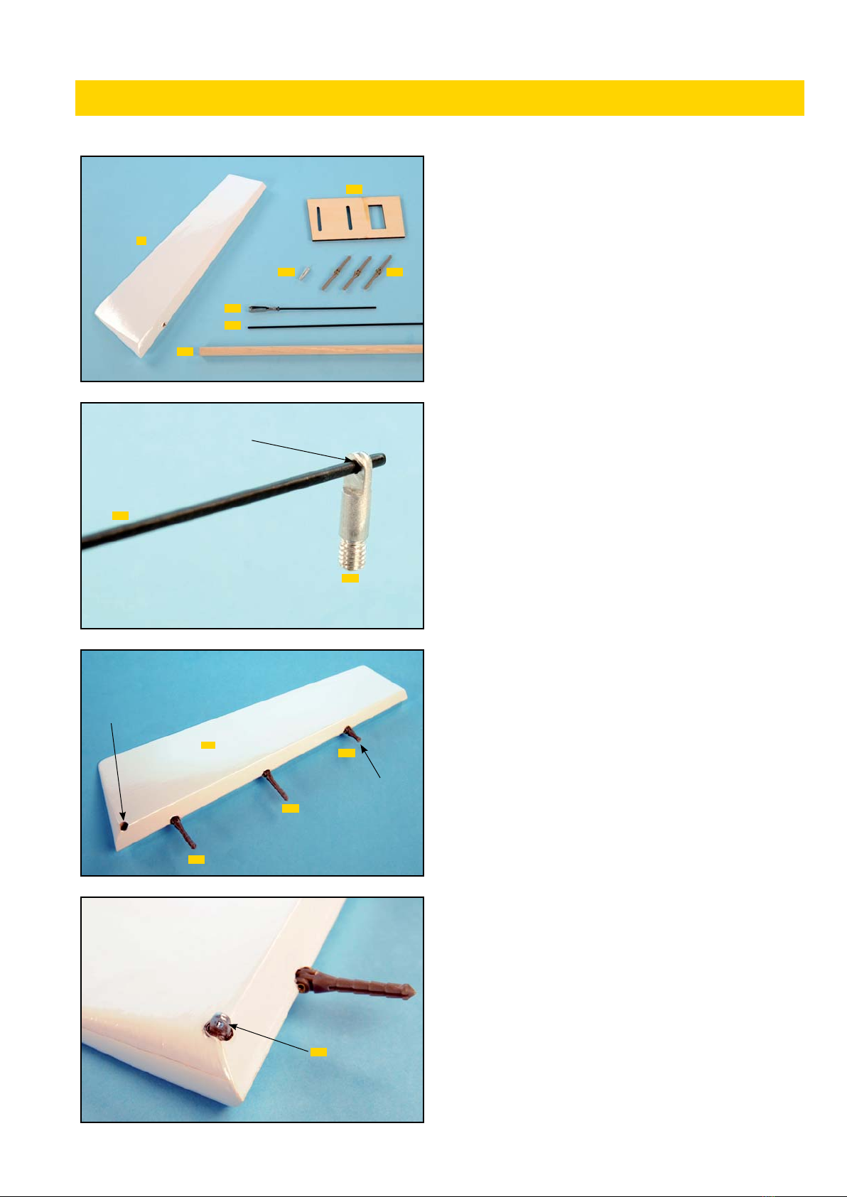
Rassembler les pièces ci-contre pour réaliser l’installation de la
direction.
Gathered parts for rudder installation.
1) Agrandir le trou du guignol 4-8 pour pouvoir recevoir la CAP 4-5.
Enlarge the hole in the control horn 4-8 to acco-
modate music wire 4-5.
2) Coller les charnières bâton 4C dans le volet de dérive 4 à l’époxy.
Raccourcir la charnière du haut comme sur la photo. Faire un trou de
4mm dans le bas du volet pour recevoir le guignol de direction.
Secure pin hinges 4C in rudder 4 with epoxy glue.
Shorten the pin at the top of rudder as photo.
Make a 4mm hole on the bottom of the rudder for
the control horn attachment.
3) Le guignol 4-8 est enfoncé dans la dérive comme sur la photo et est
collé à la colle époxy.
The control horn 4-8 is inserted up to the position
of the photo and it bonds with the epoxy adhesive.
INSTALLATION DIRECTION/ RUDDER INSTALLATION
Agrandir le trou à 1,8mm
Enlarge hole to 1,8mm
4
4-5
4-8
4-8
4C
4C
4C
4-8
1-2
4C
4-5
4-5
4
4-5
Couper l’excédent
Cut excess
Faire un trou
Make hole
18
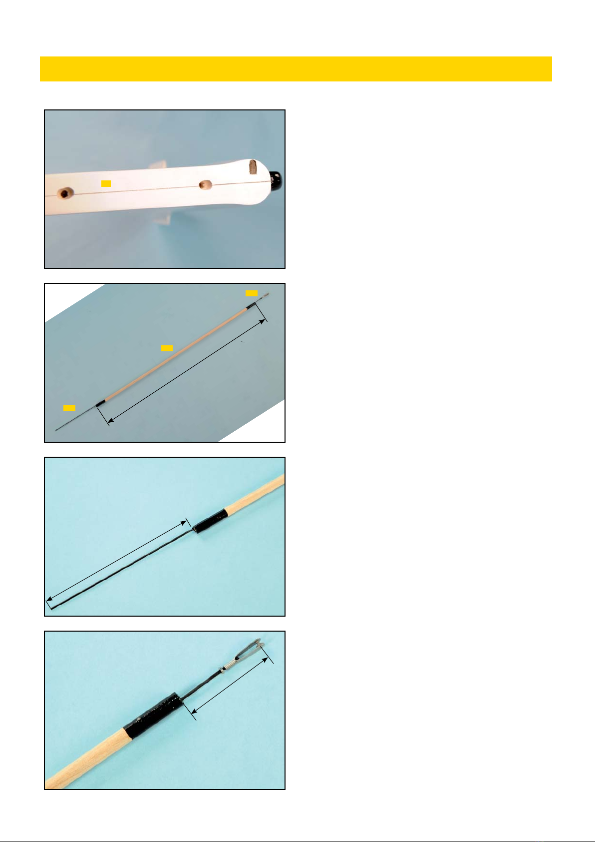
4) Faire un trou pour la sortie de la tringlerie dans l’étambot près
du bord. Parce que la tringlerie bouge horizontalement, faire un trou
oblong comme montré sur la photo.
Make exit hole for pushrod in the bottom of tail
section near edge. Because the pushrod moves
horizontaly, make elongated hole as shown in the
photo.
5) Construire la tringlerie comme montré. Utiliser le tourillon bois dur
Ø8mm 4-5 et les 2 CAP 4-5. Fixer les CAP sur le bois dur avec un tube
thermo-rétractable (non fourni).
Assemble the pushrod as shown. Use 8mm push
rod 4-5, music wires 4-5 and 4-5. Secure music
wires to hard wood with heat shrink tube
(not included).
7) Côté servo, installer la CAP filetée à un bout puis visser l’écrou M2 et
la chape comme sur la photo.
The servo side installs with 1,8mm music wire,
2mm nut and clevis as shown in the photo.
6) Installer la CAP L=250mm comme montré sur la photo. Après avoir
passé la tringlerie dans le fuselage, couder la CAP pour l’attacher au
guignol.
The rudder side installs 1,8mm music wire as
shown in the photograph. After the rod is routed
through the fuselage, it bends to attach the horn.
INSTALLATION DIRECTION/ RUDDER INSTALLATION
4-5
4-5
4-5
1
590mm
Côté volet de dérive
Rudder side
Côté servo
Servo side
150mm
50mm
19
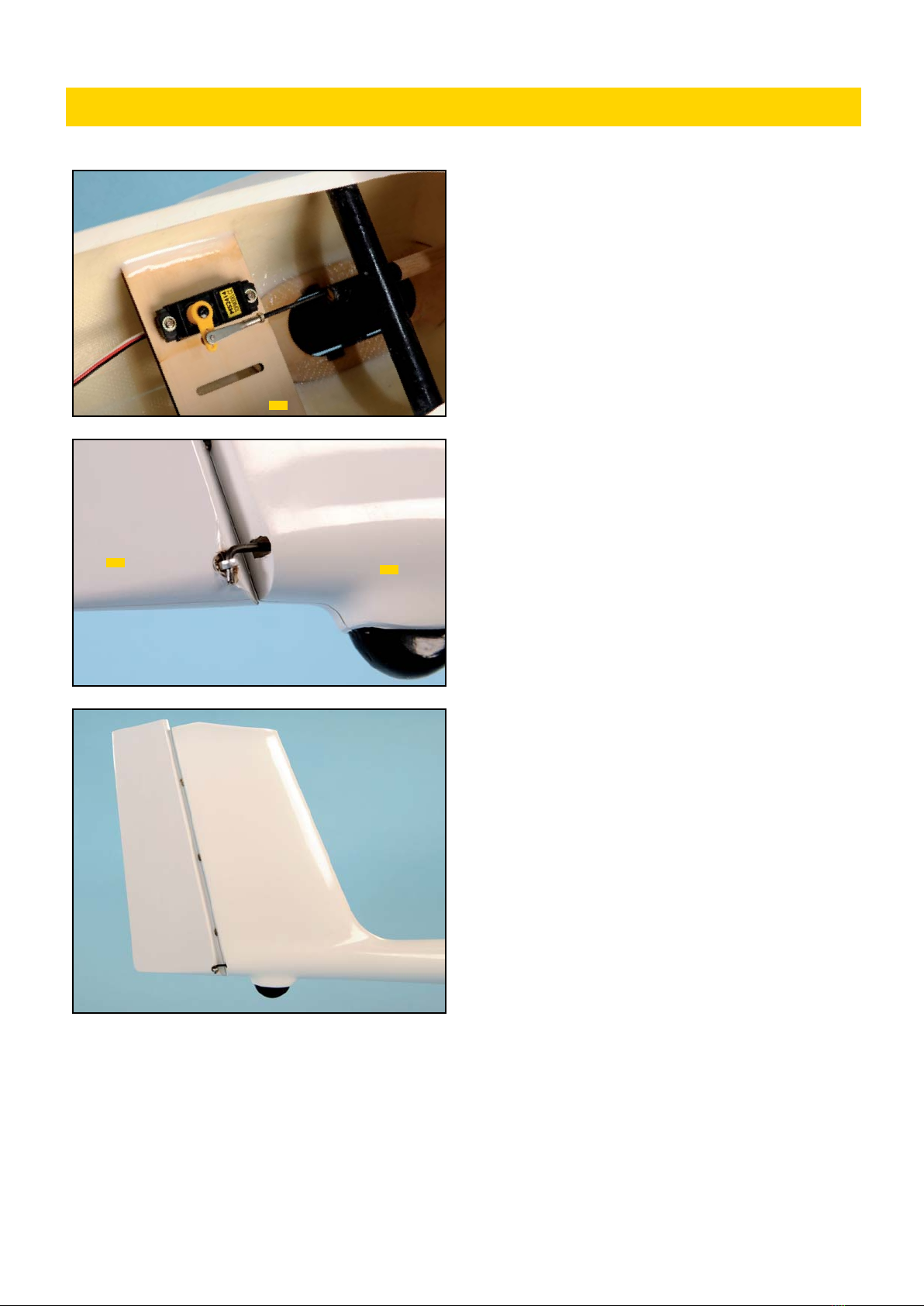
8) La platine servo 1-2 est collée à l’époxy et le servo de direction est
installé.
The servo mount 1-2 is bonded to the body with
the epoxy adhesive and the rudder servo is in-
stalled.
9) Monter temporairement la dérive 4 sur le fuso 1. Couder la CAP en L
pour la connecter au guignol comme montré. Couper l’excédent.
Temporarily fix rudder 4 to tail. Make L-bend in
music wire to connect to horn as shown. Cut off
excess music wire.
10) Coller le volet de dérive en enduisant les charnières bâton d’époxy.
Nettoyer l’excès de colle sur la partie mobile des charnières.
Install rudder into tail with epoxy glue to pin
hinge. Make sure to wipe off excess glue from
moving part of hinges.
INSTALLATION DIRECTION/ RUDDER INSTALLATION
41
1-2
20
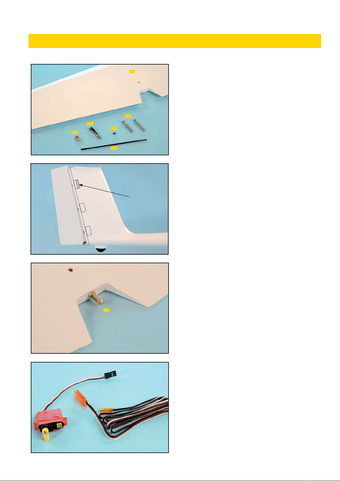
Rassembler les pièces ci-contre pour réaliser l’installation de l’empen-
nage horizontal.
Gathered parts for horizontal stabilizer installa-
tion.
1) De manière à ce que la tringlerie de profondeur ne cogne pas dans
le bloc de renfort pour la fixation de la charnière supérieure (photo),
ce bloc doit être coupé ou poncé. On peut y accéder via l’ouverture
pratiquée au sommet de l’empennage vertical.
So as not to hit the elevator linkage, the pin hinge
reinforcement block in tail part as photograph
should be cut out or sanded down. It can be ac-
cessed through holes in the top of the tail.
2) Percer un trou de 3mm au centre du volet de profondeur pour le
guignol 3-8. Coller le guignol dans le volet avec de la colle époxy.
Make a 3mm hole in the center of the elevator for
the control horn 3-8. Secure horn in the horizon-
tal stab with epoxy glue.
3) Couper les pattes de montage du servo. Envelopper le servo dans
de la gaine thermo-rétractable ou avec du scotch d’électricien comme
sur la photo. `
Coller le servo dans le plan vertical avec de la colle silicone.
Cut off the mounting tabs from both sides of the
servo. Cover servo with heat shrink tube or tape
as photo.
Secure servo in vertical tail with silicon sealer.
4) Connecter une rallonge de 800mm au servo de profondeur.
Connect 800mm extension cord (not included) to
elevator servo.
INSTALLATION EMPENNAGE HORIZONTAL/ HOR. STABILIZER INSTALLATION
3-8
3-5
3-5
3-5
3-4
3
3-8
Couper
Cut out
This manual suits for next models
1
Table of contents
Other Topmodel Aircraft manuals


Popular Aircraft manuals by other brands

Textron
Textron Cessna Citation Excel Operation manual

SOL paragliders
SOL paragliders Hercules 2 240 manual

KANGKE INDUSTRIAL
KANGKE INDUSTRIAL Pitts Python ARF Assembly manual
Air Creation
Air Creation Pixel 303 XC Instruction and maintenance handbook

Gin
Gin Bolero 6 Inspection manual

Cessna
Cessna SKYHAWK 1976 Pilot operating handbook


Raytheon
Raytheon Beech Baron A55 Shop Manual

SKY PARAGLIDERS
SKY PARAGLIDERS METIS 2 Series manual

Fly Products
Fly Products Eco 2 owner's manual

Aveo Engineering
Aveo Engineering Mooney M20 Series Installation instruction

Airplane Factory
Airplane Factory SLING 4 Pilot operating handbook

GRAVITY
GRAVITY X duo manual