MEGASTEK GVT-430 User manual
User Manual of Tracker
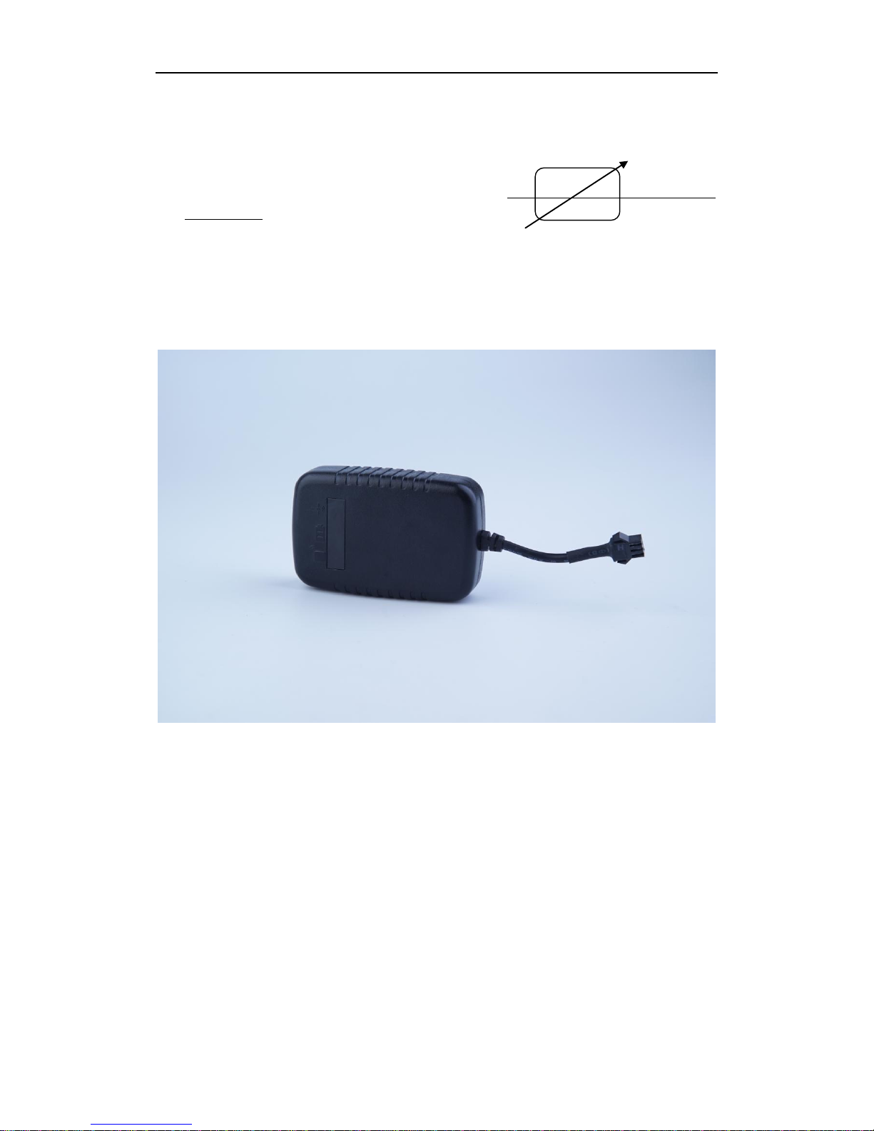
GVT-430
GPS Vehicle Positioning Tracker
_______________________________________
___
User Manual V1.1

User Manual
- 1 -
- 1 -
Contents
1. Products Overview .....................................................................................................................- 2 -
2. For Your Safety............................................................................................................................- 2 -
3. Tracker Characteristics................................................................................................................- 3 -
4. Getting Started ...........................................................................................................................- 4 -
4.1 Hardware and Accessories....................................................................................................................- 4 -
4.2 Function key and Interfaces..................................................................................................................- 4 -
4.3 LED indicator light and wire..................................................................................................................- 4 -
4.4 First Start ..............................................................................................................................................- 5 -
5. Parameter Configuration............................................................................................................- 7 -
5.1 Set by SMS ............................................................................................................................................- 7 -
5.2 Set by GPRS...........................................................................................................................................- 7 -
6. Change Password .......................................................................................................................- 7 -
7. Authorized number ....................................................................................................................- 7 -
8. Three kinds of tracking mode .................................................................................................- 8 -
9. Tracking by GPRS .....................................................................................................................- 9 -
10. Geo-fence.................................................................................................................................- 9 -
11. Set the time zone...................................................................................................................- 10 -
12. Tracking by distance or angle ................................................................................................- 10 -
13. Input application/Ignition detector .......................................................................................- 10 -
14. Low battery alarm and automatically Power on/off .............................................................- 11 -
15. Timer Switch .............................................................................................................................- 11 -
16. Problems & Diagnostics .........................................................................................................- 11 -
User Manual
- 2 -
- 2 -
1. Products Overview
Tracker is a GPS/ GPRS based tracking device designed for heavy motorbike, intercity bus,school bus
and fleet management And support WCDMA 3 G network.
It has built-in terminals of GPS module and GSM communication module, which are used for getting
the location data and send it to authorized phone number via SMS, and tracking through free maps
Google Earth or Google Map; at the same time, the GSM module can be sent data to the internet
server, which can realize the checking, monitoring and managing of the device on computer.
2. For Your Safety
Read these simple guidelines. Not following them may damage to the tracker or not perform proper function of
application.
Correct Connection
When connecting with other tracker, read carefully its manual so as to carry
out correct installation. Do not connect it to other incompatible trackers.
Chosen Accessories
Use our chosen accessories to avoid damage to tracker.
Hidden Installation
In order to avoid damage by external force intentionally, please install
tracker in a hidden place.
Protect from blasting
Follow related restrictions. Do not use tracker when blasting is in progress.
Repair and service
Only qualified engineer with technical support can repair tracker.

User Manual
- 3 -
- 3 -
3. Tracker Characteristics
3G WCAMA
SMS /GPRS tracking (support TCP/UDP)
External GPS&GSM antenna (optional built in GPS & GSM antenna )
Wide voltage range input 9-90v (for high power and electric motorcycle application )
WiFi positioning (Optional )
External battery 20,000 mAh for long time continuous secret tracking (Optional )
Geo-fence alarm
Overspeed detection
Ignition detection
ACC detection
GPS antenna cut off /external power off alarm
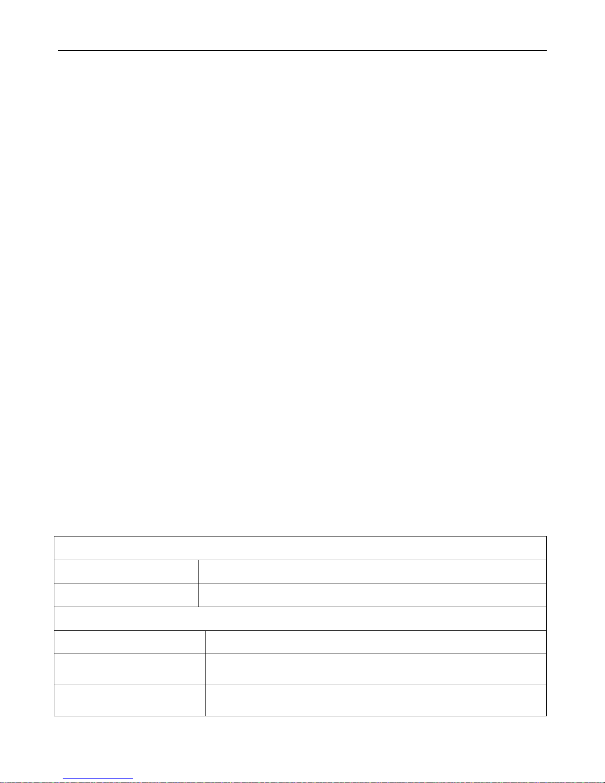
Items
Specification
Charging Voltage
DC 9-90V/1.5A
Working current
70mA
Internal memory
8M
Dimension
88mm X 50mm X 20mm
Weight
90g
Built-in battery
820mAh
Operating Temperature
-20 ~+55 °C
GSM Module
GSM850MHZ/EGSM900MHz/DCS1800MHz/PCS1900MHz
WCDMA900MHz/WCDMA2100MHz
* Two types of modules, when using, must confirm local 2 g (GSM) and the
frequency of 3 g (WCDMA)
GPS Chipset
Ublox chipset
GPS Sensitivity
-161dB
GPS Frequency
L1, 1575.42 MHz
C/A Code
1.023 MHz
Channels
50 Channels
Position Accuracy
<10 M, 2D RMS
Velocity Accuracy
0.1 M/S
Time Accuracy
Satellite Time :1 millisecond time synchronization
Update Time
Average 0.1 second
Hot Start up
Average 1 second
Warm Start up
Average 31second
Cold Start up
Average 29 second
Cold Start up Max.
Altitude 18,000m (Max. 60,000 ft)
Max. Speed
515 m/s (max.1000 knots).
Max. Acceleration
Less than 4g
LED
Three LED for showing states of power、GPS、GSM

User Manual
- 4 -
- 4 -
4. Getting Started
This section will describe how to use the tracker.
4.1 Hardware and Accessories
GPS antenna GSM antenna external power connecting wire
4.2 Function key and Interfaces
4.3 LED indicator light and wire
Red LED- Power
Always on
Charging
1s on and 3s off
Normally work
Blue LED- GSM
0.3s on and 0.3s off
GSM module is initializing
Always on
Failed to registered network
1s on and 3s off
GSM module is registered network
0.1s on and 3s off
GSM module is registered network and GPRS function works well
Power LED
GPS LED
GSM LED
The external GSM antenna port The external GPS antenna port
The external power connecting port

User Manual
- 5 -
- 5 -
Orange LED- GPS
0.3s on and 0.3s off
GPS module initializing
1s on and 3s off
GPS module works well, but GPS position is not fixed
0.1s on and 3s off
GPS module works well and GPS position is fixed
port
The external GSM antenna port
Connect the GPS antenna
The external GPS antenna port
Connect the GSM antenna
The external power connecting port
Connect the device
4.4 First Start
Please read this manual before using tracker and check if all parts are included in the packaging box.
4.4.1 Ensure that your tracker has a working SIM card.
- Check that the SIM card has not run out of credit (Test the SIM card in a phone to make sure it can
send and receive SMS)
- Check that lock code of the SIM card is turned off.
- If you require the function of sending an SMS location report to the authorized phone number when
it makes a call to the tracker, please make sure the SIM card installed supports displaying caller ID.
4.4.2 Install SIM card and turn on, see pictures below:
1. Open the SIM holder and Insert SIM card 2. Turn on the switch behind the SIM card 3. Install the cover of the SIM card

User Manual
- 6 -
- 6 -
4.4.3 Install GSM antenna and GPS antenna, see pictures below:
GPS antenna
GSM antenna
When installing the antenna, please note that different antennas correspond to different port.
4.4.4 Install external power connecting wire
The external power
connecting wire Connection
method:
One end: black line 、red line and white line connected to the
corresponding position of the vehicle.
The other end: Connect the device to the external power connecting
port
The main purpose of the
external power connecting
wire:
1. After started, the vehicle charge the device.
2. Vehicle ignition detection
Connect the device
User Manual
- 7 -
- 7 -
5. Parameter Configuration
There are 3 ways to set parameter: set by SMS, set by GPRS.
5.1 Set by SMS
Users can set the parameter of tracker by mobile phone SMS, see <command list> from the
<Communication protocol>.
Note: all commands are SMS commands in this manual.
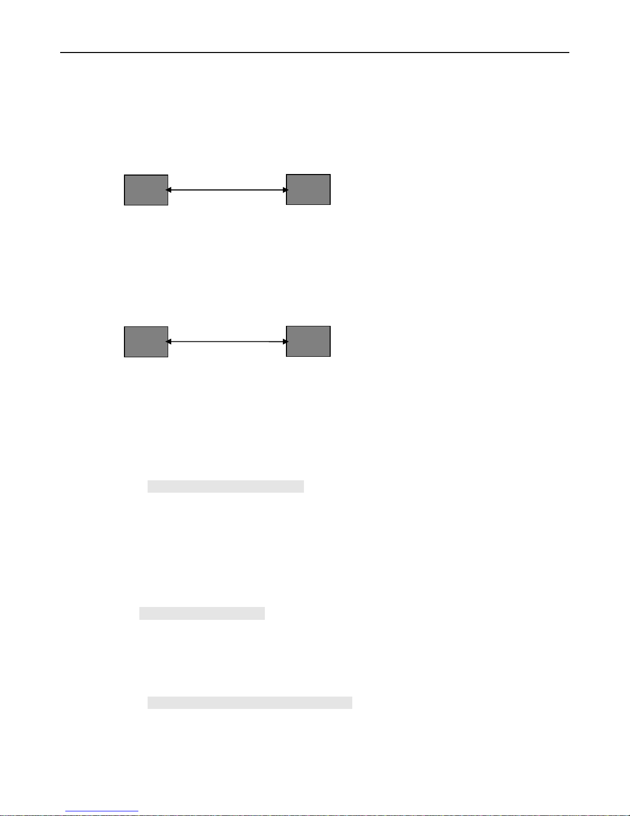
5.2 Set by GPRS.
Users can set the parameter of tracker by server, see <command list> from the <Communication
protocol>.
6. Change Password
SMS Command: $SMS,000000;W001,123456;!
Describe: change user password
Explain:
All the SMS commands must be capitalized and please switch to English input method when you edit.
1. ‘000000’ is user’s password, the default password is ‘000000’. Device will only accept commands
from a user with the correct password. Otherwise command will be ignored
2. ‘123456’ is the new password, password must be 6 digits
For example: $SMS,000000;W001,123456;!
7. Authorized number
SMS Command: $SMS,000000;W010,NO.,Phone Number,ABC;!
Description: Set authorized phone number and its related functions
Explain:
Server
Tracker
GPRS
Phone
Tracker
SMS

User Manual
- 8 -
- 8 -
NO.: authorized number’s serial number, range of: 1~3
Phone Number: authorized number, range of: 0~19 characters
A: range of: 0~1; when the parameter ‘A’is 0, it means disable Geo-fence alarm, otherwise it means
enable Geo-fence alarm. Default is 0
B: range of: 0~1; No monitoring function, Default is 0
C: range of: 0~1; No SOS emergency calling function, Default is 0
For example:
Read authorized No.1 and it’s related authority:$SMS,000000;R010,1;!
Clear authorized No.1 and it’s related authority:$SMS,000000;C010,1;!
Read all authorized number:$SMS,000000;R010;!
Clear all authorized number:$SMS,000000;C010;!
8. Three kinds of tracking mode
SMS Command: $SMS,000000;W016,X;!
Description: there are three kinds of mode: personal mode, smart mode, vehicle mode.
Explain:
X: tracker’s work mode. Range of: 0~2 (0 means personal mode, 1 means smart mode, 2 means
vehicle mode). Default: 1.
Personal mode: When there are new data or alarms, GPS turns on the positioning function
automatically. No matter the positioning succeeds or fails, GPS turns off the positioning function
automatically, and upload new data or send out alert message.
Smart mode: GPS always turn on when device is move; otherwise only when there are new
data or alarms, GPS turns on the positioning function automatically. No matter the positioning
succeeds or fails, GPS turns off the positioning function automatically, and upload new data or
send out alert message.
Vehicle mode: GPS always turn on whether tracker move or not.
Example:
$SMS,000000;W016,1;!
Read device mode:$SMS,000000;W016,1;!
Clear device mode:$SMS,000000;W016,1;!

User Manual
- 9 -
- 9 -
9. Tracking by GPRS
SMS Command: $SMS,000000;W002,APN,Username,Password;W003,IP,Port;W004,ID;W005,X;W009,Y;!
Description: enable GPRS tracking function.
Explain:
1. APN: access point name of network
2. Username and Password are optional. If you don’t know what they are, please just input APN
only
3. APN + Username + Password should not be over 64 characters
4. IP: server’ IP address or domain name
5. Port: Max. 65535
6. ID: device ID
7. X: GPRS upload interval, unit is 30s,X=1: Set the upload interval is Each every 30 send once.
8. Y: GPRS upload mode, range of: 0~20 means disable GPRS function, 1 means upload by TCP, 2
means upload by UDP
Example:$SMS,000000;W002,cmnet,,;W003,192.168.1.1,8088;W005,60;W009,1;!
10.Geo-fence
SMS command:
$SMS,000000;W018, NO.,name,lat,lng,radius;!
Describe: enable Geo-fence alarm. When the tracker moves in/out the preset geo-fence, tracker will
send an alarm by SMS to the authorized number and send this data to server if GPRS is connected.
Explain:
NO.: serial number for geo-fence must be 1 to 5
name: max. 10 characters
lat: Latitude, format is dd.dddddd, the unit is degree, if it is northern latitude, minus is needed.
Otherwise, omit it
lng: Longitude, formats is ddd.dddddd, the unit is degree, if it is east longitude, minus is needed.
Otherwise, omit it
radius: Max. 99999.00, the unit is Km
Based on preset longitude and latitude as the center of the circle, and the preset radius, a circle is
defined.
For example:
$SMS,000000;W018,1,school,22.12345,114.12345,10.50;!
$SMS,000000;W018,2,office,12.12345,-45.12354,10.75;!

User Manual
- 10 -
- 10 -
11.Set the time zone
Set the time zone of SMS
SMS command:
$SMS,000000;W020,X;!
Describe: Choose time zone of SMS, time zone default is GMT 0.
Explain:
X=time zone value, please plus"-"in front if it is a negative, otherwise, ignore it. Unit is minutes
(New York’s time zone is -300minutes)
For example:
$SMS,000000;W020,480;!
12.Tracking by distance or angle
SMS Command: $SMS,000000;W006,X;W007,Y;!
Describe: this command used for enable this function.
X is distance value, unit is meter; Y is angle value, unit is degree (Suggest X=150 Y=20)
For example:
$SMS,000000;W006,100;W007,15;!
13.Input application/Ignition detector
ACC used for ignition detection. The detection flag and alarm will be sent to the server through
GPRS when flag changes. Please refer to <GPRS Communication Protocol> for more information.
ACC
Power for ignition
Battery
Ignition switch
User Manual
- 11 -
- 11 -
14.Low battery alarm and automatically Power on/off
When the battery level is lower than 15%, it will send SMS to all authorized numbers or send alarm
data to server. Tracker will be off automatically
if the power level is 0%; during charging, tracker will automatically switch on when power level is
higher than 15%, and send a warning SMS to all authorized number.
15. Timer Switch
SMS Command:$SMS,000000;W038,on time,off time;!
Description: set the timer switch
Explain:
on time: timing boot time, range of:00:00~23:59,default: 00:00.
off time: timing shutdown time, range of:00:00~23:59,default: 00:00.
For example: $SMS,000000;W038,08:00,20:00;!
This command means to boot up at 08:00 and shutdown at 20:00.
16.Problems & Diagnostics
Problem: Tracker can not turn on
Possible cause
Solution
Low power
Charging
Problem: Tracker can not reply with SMS
Possible cause
Solution
GSM network is busy
Please wait a moment. Tracker maybe not react instantly when GSM network is
busy or tracker is in failure.
Wrong password in your SMS or
wrong SMS format
Write correct password or SMS format.

User Manual
- 12 -
- 12 -
The SIM card has run out of credit
Replace or recharge value of the SIM card.
SIM card is damaged or warped
Inspect SIM, and clean the contact. If re-inserting does not help, try another
one.
Problem: tracker cannot get the GPS location
Possible cause
Solution
As a vehicle
tracker
GPS external antenna is not
installed
Install GPS external antenna.
GPS external antenna is
incorrectly installed
Reinstall GPS external antenna correctly (see 4.3.First start).
As a personal
tracker
The GPS signal is weak.
Move the unit to a location where the sky is visible. Tall buildings,
trees, and heavy rain, can cause problems with the GPS reception.
The front side of tracker is
down
Place the front side of tracker towards clear sky.
Problem: Tracker Fails to Connect to Server via GPRS
Possible cause
Solution
SIM card in tracker does not support
GPRS function
Enable SIM card GPRS function.
GPRS function of tracker is turned off
Turn on GPRS function of tracker.
Incorrect IP address or PORT
Get the right IP address and PORT and reset to tracker.
GSM signal is weak
Move the tracker to a location with good GSM reception.
Table of contents
Other MEGASTEK GPS manuals


