manuals.online logo
Brands
  1. Home
  2. •
  3. Brands
  4. •
  5. Transmitter Solutions
  6. •
  7. Accessories
  8. •
  9. Transmitter Solutions IGAZE iGAZER45P User manual

Transmitter Solutions IGAZE iGAZER45P User manual

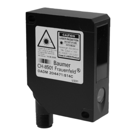
INSTALLATION MANUAL
iGAZER45P
Polarized Photo Eyes
FEATURES:
• Range 45-50 feet
• Immune to external light sources
• High degree of protection
• Optional cable entry
• Terminal compartment
• Polarisation filter optical system
• Test input
• Operating voltage 10-40VDC or 24VAC ±25%
• Protected against power supply polarity reversal
• Relay output
• Easy adjustment of the optical sensor
• Dirt indicator
• LED alignment indication
TECHNICAL DATA
1-3/4”
3-3/8”
1-1/2”
1”
Operating voltage 10...40VDC
24VAC, ± 25%
Operational <100ms after power on
Current consumption max. 30mA/24V
Type of light red, 680nm
pulsed, polarised
Aperture angle approx. 1.5° total angle
Output relay, changeover contact
Switch rating min. 1mA/min. 5VDC
max. 0.6A/50V AC
max. 0.5A/48VDC
(resistive load)
Response time <10ms, detection of light
beam interruption
Relay delay when the light beam is
uninterrupted again, the relay
picks up with 100ms delay
Type of switching responsive to brightness, i.e.
the relay picks up when the
light beam is uninterrupted
Ranges 45-50 feet
Indications dual LED r ed/green
Light beam interrupted = lights up r ed
Light beam uninterrupted, spare critical function capacity.
= flashes red at 4Hz
Light beam uninterrupted, high spare function capacity.
= lights up green
Additional function test input
(when 0V at terminal 1 the
transmitter switches off)
Type of connection screw terminal max. 1.5mm²
Casing material lower part: ABS-GF15%
upper part: PMMA, red
Degree of protection IP67, to EN60529
Operating temp. -13°...140°F
Storage temp. -31°...176°F
Weight approx. 2 oz
Size 3-3/8 x 1-3/4 x 1-1/2 in³ (LxWxH)
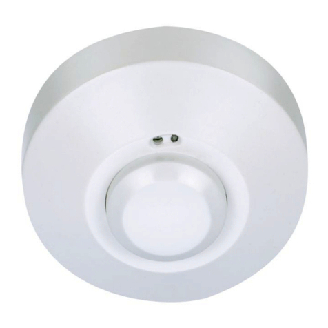
TERMINAL ASSIGNMENTS
Test input
at 0V
GND
max.
0,5A/48VDC
PWR
1-5/16”
2-7/8”
ø 1/8”
Rubber grommet
or
Cable gland
M12x1,5
optional cable entry
7/16”
FINE ADJUSTMENT
Hole spacing
LED lights up:
100 % of the cone of light is
hitting the reflector
LED flashing:
L ess than 100 % of the cone
of light is hitting the reflector
ACCESSORIES
SIZE
NOTE: For test purposes the photo-electric switch switches the
transmitter off when GND is applied to ter minal 1. For reasons of
safety the photo-electric switch is responsive to brightness, so that
the relay picks up when the light beam is uninterrupted.
NOTE: The cable entry is
moulded into the lower
part of the casing and
can be broken out.
Either the rubber
grommet or the cable
gland (both supplied)
can be used.
After mounting the photo-switch the light beam can be
adjusted using 3 screws.
IMPORTANT NOTE!
The optical sensor is spring-mounted. All 3 screws are
unscrewed by 1 turn factory-made, the maximum is 3
turns. The optical sensor is optimally aligned when the
green LED lights up constantly.
RAIN COVER FOR THE REFLECTOR.
protection against rain, hail and snow,
impact resistant, UV-stable
material: PA6 GF15
RAIN COVER FOR THE PHOTO-EYE
protection against rain, hail and snow,
impact resistant, UV -stable
material: PA6 GF15
WARRANTY
The warranty period of this product is 24 months, beginning from the
manufacturing date. During this period, if the product does not operate
correctly, due to a defective component, the product will be repaired or
replaced at the sole discretion of Transmitter Solutions. This warranty does not
extend to the product casing which can be damaged by conditions outside of
the control of Transmitter Solutions.

Other Transmitter Solutions Accessories manuals

Transmitter Solutions iGAZER32P-10K/NC Operating and maintenance manual

Transmitter Solutions

Transmitter Solutions iGAZER32P-10K/NC Operating and maintenance manual

Popular Accessories manuals by other brands

PCB Piezotronics 352C67 Installation and operating manual

PCB Piezotronics

PCB Piezotronics 352C67 Installation and operating manual

Velodyne VLP-16 user manual

Velodyne

Velodyne VLP-16 user manual

weinor Cassita II Maintenance instructions and directions for use

weinor

weinor Cassita II Maintenance instructions and directions for use

Philio PST07 manual

Philio

Philio PST07 manual

Pico Macom MPCD Specifications

Pico Macom

Pico Macom MPCD Specifications

ISLAND HOPPER Classic owner's manual

ISLAND HOPPER

ISLAND HOPPER Classic owner's manual

ipf electronic RO570900 manual

ipf electronic

ipf electronic RO570900 manual

Dometic CB40 operating manual

Dometic

Dometic CB40 operating manual

Terragene BIONOVA MiniBio manual

Terragene

Terragene BIONOVA MiniBio manual

Avery Weigh-Tronix WI-127 user manual

Avery Weigh-Tronix

Avery Weigh-Tronix WI-127 user manual

FAAC XP15W manual

FAAC

FAAC XP15W manual

Davis Instruments Anemometer Drip Rings install guide

Davis Instruments

Davis Instruments Anemometer Drip Rings install guide

National Instruments FIELDPOINT CFP-CB-1 operating instructions

National Instruments

National Instruments FIELDPOINT CFP-CB-1 operating instructions

ROSE DISPLAYS ADVANCETRAK WITH METAL CLIP AND V CLIP manual

ROSE DISPLAYS

ROSE DISPLAYS ADVANCETRAK WITH METAL CLIP AND V CLIP manual

Mi PLM13ZM user manual

Mi

Mi PLM13ZM user manual

Rice Lake Ranger Series Operation manual

Rice Lake

Rice Lake Ranger Series Operation manual

Wasserstein BlinkDBSolarCharBlkUSN user manual

Wasserstein

Wasserstein BlinkDBSolarCharBlkUSN user manual

Spinfire Pro 2 manual

Spinfire

Spinfire Pro 2 manual

manuals.online logo
manuals.online logoBrands
  • About & Mission
  • Contact us
  • Privacy Policy
  • Terms and Conditions

Copyright 2025 Manuals.Online. All Rights Reserved.