Topp Music Gear Mx2442 User manual

24
OUTPUT LEVEL
SOLO MODE
TO AUX
TO AUX
MAIN MIX
TO L RTO L R
SUB 3 4
MAIN MIX
CTRL R
SEND2
STEREO AUX RETURNS
SOLO
AUX SENDS
SEND1
SOLO ACTIVE
LEVEL SET
CTRL ROOM SOURCE
SOLO
SOLO
SOLO
10
20
7
LR
30
10
CLIP
7
0
FREQFREQFREQFREQFREQFREQFREQFREQFREQ FREQ FREQ FREQ
MIDMIDMIDMIDMIDMIDMIDMIDMID MID MID MID
BAL BAL BAL BAL BAL BAL
80Hz80Hz80Hz80Hz80Hz80Hz80Hz80Hz80Hz 80Hz 80Hz 80Hz 80Hz 80Hz 80Hz 80Hz 80Hz 80Hz
LOWLOWLOWLOWLOWLOWLOWLOWLOW LOW LOW LOW LOW LOW LOW LOW LOW LOW
800800800800800800800800800 800 800 800
100Hz100Hz100Hz100Hz100Hz100Hz100Hz100Hz100Hz 100Hz 100Hz 100Hz
8KHz8KHz8KHz8KHz8KHz8KHz8KHz8KHz8KHz 8KHz 8KHz 8KHz
EQEQEQEQEQEQEQEQEQ EQ EQ EQ EQ EQ EQ EQ EQ EQ
HIHIHIHIHIHIHIHIHI HI HI HI HI HI HI HI HI HI
12kHz12kHz12kHz12kHz12kHz12kHz12kHz12kHz12kHz 12kHz 12kHz 12kHz 12kHz 12kHz 12kHz 12kHz 12kHz 12kHz
HI MID-HIMID-HIMID-HIMID-HIMID-HIMID-
3kHz 3kHz 3kHz 3kHz 3kHz 3kHz
500Hz 500Hz 500Hz 500Hz 500Hz 500Hz
MID LOW-MID LOW-MID LOW-MID LOW-MID LOW-MID LOW-
SUB 1 2
RIGHTRIGHTRIGHTRIGHTRIGHT RIGHT B
LINE IN 21LINE IN 19LINE IN 17LINE IN 15LINE IN 13
LINE IN 22
LINE IN 20LINE IN 18LINE IN 16
LINE IN 14
INSERTINSERTINSERTINSERTINSERTINSERTINSERTINSERTINSERTINSERTINSERTINSERT
BAL UNBALBAL UNBALBAL UNBALBAL UNBALBAL UNBALBAL UNBALBAL UNBALBAL UNBALBAL UNBALBAL UNBALBAL UNBALBAL UNBAL
LINE IN 12LINE IN 11LINE IN 10LINE IN 9LINE IN 8LINE IN 7LINE IN 6LINE IN 5LINE IN 4LINE IN 3LINE IN 2LINE IN 1
LINE IN 24
(MONO)(MONO)(MONO)(MONO)(MONO)
LEFTLEFTLEFTLEFTLEFT
BAL UNBALBAL UNBALBAL UNBALBAL UNBALBAL UNBAL
(MONO)
LEFT
BAL UNBAL
PHONES
A
L
TAPE IN
R
TAPE OUT
2-TRACK IN OUT
LINE IN 23
TO L R TO L R
2TK IN
TO MAIN MIX
PHONES
CTRL ROOM
MAIN MIX
2TK IN
SUB 1 2
SUB 3 4
PWR
INSERTINSERT
MAIN MIX
OUTPUT L
MAIN MIX
OUTPUT R
5V
0.5A
LAMP
AFL
PFL
MIC9MIC8MIC7MIC6MIC5MIC4MIC3MIC2MIC1 MIC10 MIC11 MIC12 MIC13 MIC14 MIC15 MIC16 MIC17 MIC18
BAL UNBAL BAL UNBAL
24-CH COMPACT INTEGRATED LIVE
SOUND MIXER
111111111 1 1 1 1 1 1 1 1 1 11
1
222222222 2 2 2 2 2 2 2 2 2 22
2
PREPREPREPREPREPREPREPREPRE PRE PRE PRE PRE PRE PRE PRE PRE PRE
POSTPOSTPOSTPOSTPOSTPOSTPOSTPOSTPOST POST POST POST POST POST POST POST POST POST
DFX2
4
DFX2
4
DFX2
4
DFX2
4
DFX2
4
DFX2
4
DFX2
4
DFX2
4
DFX2
4DFX2
4DFX2
4DFX2
4DFX2
4DFX2
4DFX2
4DFX2
4DFX2
4DFX2
444
3DFX1
3DFX1
3DFX1
3DFX1
3DFX1
3DFX1
3DFX1
3DFX1
3DFX1 3DFX1 3DFX1 3DFX1 3DFX1 3DFX1 3DFX1 3DFX1 3DFX1 3DFX1 33
MAX
TRIMTRIMTRIMTRIMTRIMTRIMTRIMTRIMTRIM TRIM TRIM TRIM TRIM TRIM TRIM TRIM TRIM TRIM
LEVELLEVELLEVELLEVELLEVELLEVELLEVELLEVELLEVELLEVEL LEVEL LEVEL LEVEL LEVEL LEVEL LEVEL LEVEL LEVEL LEVEL
SETSETSETSETSETSETSETSETSETSET SET SET SET SET SET SET SET SET SET
OdBOdBOdBOdBOdBOdBOdBOdBOdB OdB OdB OdB OdB OdB OdB OdB OdB OdB50dB50dB50dB50dB50dB50dB50dB50dB50dB 50dB 50dB 50dB 40dB 40dB 40dB 40dB 40dB 40dBMICMICMICMICMICMICMICMICMIC MIC MIC MIC MIC MIC MIC MIC MIC MIC
35dB35dB35dB35dB35dB35dB35dB35dB35dB 35dB 35dB 35dB 20dB 20dB 20dB 20dB 20dB 20dBLINELINELINELINELINELINELINELINELINE LINE LINE LINE LINE LINE LINE LINE LINE LINE
PAN PAN PAN PA N
LINE
USB
LINE
MP3
MX2442
LOW CUT
75Hz
18dB Oct
LOW CUT
75Hz
18dB Oct
LOW CUT
75Hz
18dB Oct
LOW CUT
75Hz
18dB Oct
LOW CUT
75Hz
18dB Oct
LOW CUT
75Hz
18dB Oct
LOW CUT
75Hz
18dB Oct
LOW CUT
75Hz
18dB Oct
LOW CUT
75Hz
18dB Oct
LOW CUT
75Hz
18dB Oct
LOW CUT
75Hz
18dB Oct
LOW CUT
75Hz
18dB Oct
LOW CUT
75Hz
18dB Oct
LOW CUT
75Hz
18dB Oct
LOW CUT
75Hz
18dB Oct
LOW CUT
75Hz
18dB Oct
PEAKPEAKPEAKPEAKPEAKPEAKPEAKPEAKPEAK PEAK PEAK PEAK PEAK PEAK PEAK PEAK PEAK PEAK
MUTEMUTEMUTEMUTEMUTEMUTEMUTEMUTEMUTE MUTE MUTE MUTE MUTE MUTE MUTE MUTE MUTE MUTE
19/20 21/22 23/24 SUB1 SUB2 SUB3 SUB410 11 12 13/14 15/16 17/18987654321 LMAIN MAIN R
4DFX2RETURN
4 DFX2 SEND
AUX RETURNS SOLO
15dB15dB15dB15dB15dB15dB15dB15dB15dB 15dB 15dB 15dB 20dB 20dB 20dB 20dB 20dB 20dB
48
SUB 1 2
SUB 3 4
MAIN L R
10
dB
5
10
20
25
30
0
5
SOLO
40
60
SUB 1 2
SUB 3 4
MAIN L R
10
dB
5
10
20
25
30
0
5
SOLO
40
60
SUB 1 2
SUB 3 4
MAIN L R
10
dB
5
10
20
25
30
0
5
SOLO
40
60
SUB 1 2
SUB 3 4
MAIN L R
10
dB
5
10
20
25
30
0
5
SOLO
40
60
SUB 1 2
SUB 3 4
MAIN L R
10
dB
5
10
20
25
30
0
5
SOLO
40
60
SUB 1 2
SUB 3 4
MAIN L R
10
dB
5
10
20
25
30
0
5
SOLO
40
60
SUB 1 2
SUB 3 4
MAIN L R
10
dB
5
10
20
25
30
0
5
SOLO
40
60
SUB 1 2
SUB 3 4
MAIN L R
10
dB
5
10
20
25
30
0
5
SOLO
40
60
SUB 1 2
SUB 3 4
MAIN L R
10
dB
5
10
20
25
30
0
5
SOLO
40
60
SUB 1 2
SUB 3 4
MAIN L R
10
dB
5
10
20
25
30
0
5
SOLO
40
60
10
dB
5
10
20
25
30
0
5
40
60
10
dB
5
10
20
25
30
0
5
40
60
10
dB
5
10
20
25
30
0
5
40
60
10
dB
5
10
20
25
30
0
5
40
60
SUB 1 2
SUB 3 4
MAIN L R
10
dB
5
10
20
25
30
0
5
SOLO
40
60
SUB 1 2
SUB 3 4
MAIN L R
10
dB
5
10
20
25
30
0
5
SOLO
40
60
SUB 1 2
SUB 3 4
MAIN L R
10
dB
5
10
20
25
30
0
5
SOLO
40
60
SUB 1 2
SUB 3 4
MAIN L R
10
dB
5
10
20
25
30
0
5
SOLO
40
60
SUB 1 2
SUB 3 4
MAIN L R
10
dB
5
10
20
25
30
0
5
SOLO
40
60
SUB 1 2
SUB 3 4
MAIN L R
10
dB
5
10
20
25
30
0
5
SOLO
40
60
SUB 1 2
SUB 3 4
MAIN L R
10
dB
5
10
20
25
30
0
5
SOLO
40
60
SUB 1 2
SUB 3 4
MAIN L R
10
dB
5
10
20
25
30
0
5
SOLO
40
60
10
dB
5
10
20
25
30
0
5
40
60
10
dB
5
10
20
25
30
0
5
40
60
12
3
12
3
12
3
12
3
12
3
12
3
12
3
12
3
12
3
12
3
12
3
12
3
12
3
12
3
12
3
12
3
12
3
12
3
12
3
12
3
PROGRAM (PUSH)
PEAK MUTE/DSP MUTE
DIGITAL STEREO EFFECTS PROCESSOR
24BITs
00-09 Vocal
10-19 Small Room
20-29 Large Hall
30-39 Echo
40-49 Echo Verb+
50-59 Flange Verb
60-69 Plate
70-79 Chorus GTR
80-89 Rotary GTR
90-99 Tremolo GTR
+
+
+
+
USB PLAYER
(Push & Hold)
POWER
TAC-MP3-T


Thank you for purchasing the TOPP PRO MX2442 compact integrated mixers, which
available for 24 channels. Your MX2442 is a remarkable compact mixer that doesn't
find many equals in the market today. With 18 MIC and 6 Stereo Line-level inputs for
MX2442
18

MX2442
MX2442.
MX2442.
MX2442
OUTPUT LEVEL
SOLO MODE
TO AUX
TO AUX
MAIN MIX
TO L RTO L R
SUB 3 4
MAIN MIX
CTRL R
SEND2
STEREO AUX RETURNS
SOLO
AUX SENDS
SEND1
SOLO ACTIVE
LEVEL SET
CTRL ROOM SOURCE
SOLO
SOLO
SOLO
10
20
7
LR
30
10
CLIP
7
0
FREQFREQFREQFREQFREQFREQFREQFREQFREQ FREQ FREQ FREQ
MIDMIDMIDMIDMIDMIDMIDMIDMID MID MID MID
BAL BAL BAL BAL BAL BAL
80Hz80Hz80Hz80Hz80Hz80Hz80Hz80Hz80Hz 80Hz 80Hz 80Hz 80Hz 80Hz 80Hz 80Hz 80Hz 80Hz
LOWLOWLOWLOWLOWLOWLOWLOWLOW LOW LOW LOW LOW LOW LOW LOW LOW LOW
800800800800800800800800800 800 800 800
100Hz100Hz100Hz100Hz100Hz100Hz100Hz100Hz100Hz 100Hz 100Hz 100Hz
8KHz8KHz8KHz8KHz8KHz8KHz8KHz8KHz8KHz 8KHz 8KHz 8KHz
EQEQEQEQEQEQEQEQEQ EQ EQ EQ EQ EQ EQ EQ EQ EQ
HIHIHIHIHIHIHIHIHI HI HI HI HI HI HI HI HI HI
12kHz12kHz12kHz12kHz12kHz12kHz12kHz12kHz12kHz 12kHz 12kHz 12kHz 12kHz 12kHz 12kHz 12kHz 12kHz 12kHz
HI MID-HIMID-HIMID-HIMID-HIMID-HIMID-
3kHz 3kHz 3kHz 3kHz 3kHz 3kHz
500Hz 500Hz 500Hz 500Hz 500Hz 500Hz
MID LOW-MID LOW-MID LOW-MID LOW-MID LOW-MID LOW-
SUB 1 2
RIGHTRIGHTRIGHTRIGHTRIGHT RIGHT B
LINE IN 21LINE IN 19LINE IN 17LINE IN 15LINE IN 13
LINE IN 22
LINE IN 20LINE IN 18LINE IN 16
LINE IN 14
INSERTINSERTINSERTINSERTINSERTINSERTINSERTINSERTINSERTINSERTINSERTINSERT
BAL UNBALBAL UNBALBAL UNBALBAL UNBALBAL UNBALBAL UNBALBAL UNBALBAL UNBALBAL UNBALBAL UNBALBAL UNBALBAL UNBAL
LINE IN 12LINE IN 11LINE IN 10LINE IN 9LINE IN 8LINE IN 7LINE IN 6LINE IN 5LINE IN 4LINE IN 3LINE IN 2LINE IN 1
LINE IN 24
(MONO)(MONO)(MONO)(MONO)(MONO)
LEFTLEFTLEFTLEFTLEFT
BAL UNBALBAL UNBALBAL UNBALBAL UNBALBAL UNBAL
(MONO)
LEFT
BAL UNBAL
PHONES
A
L
TAPE IN
R
TAPE OUT
2-TRACK IN OUT
LINE IN 23
TO L R TO L R
2TK IN
TO MAIN MIX
PHONES
CTRL ROOM
MAIN MIX
2TK IN
SUB 1 2
SUB 3 4
PWR
INSERTINSERT
MAIN MIX
OUTPUT L
MAIN MIX
OUTPUT R
5V
0.5A
LAMP
AFL
PFL
MIC9MIC8MIC7MIC6MIC5MIC4MIC3MIC2MIC1 MIC10 MIC11 MIC12 MIC13 MIC14 MIC15 MIC16 MIC17 MIC18
BAL UNBAL BAL UNBAL
24-CH COMPACT INTEGRATED LIVE
SOUND MIXER
111111111 1 1 1 1 1 1 1 1 1 11
1
222222222 2 2 2 2 2 2 2 2 2 22
2
PREPREPREPREPREPREPREPREPRE PRE PRE PRE PRE PRE PRE PRE PRE PRE
POSTPOSTPOSTPOSTPOSTPOSTPOSTPOSTPOST POST POST POST POST POST POST POST POST POST
DFX2
4
DFX2
4
DFX2
4
DFX2
4
DFX2
4
DFX2
4
DFX2
4
DFX2
4
DFX2
4DFX2
4DFX2
4DFX2
4DFX2
4DFX2
4DFX2
4DFX2
4DFX2
4DFX2
444
3DFX1
3DFX1
3DFX1
3DFX1
3DFX1
3DFX1
3DFX1
3DFX1
3DFX1 3DFX1 3DFX1 3DFX1 3DFX1 3DFX1 3DFX1 3DFX1 3DFX1 3DFX1 33
MAX
TRIMTRIMTRIMTRIMTRIMTRIMTRIMTRIMTRIM TRIM TRIM TRIM TRIM TRIM TRIM TRIM TRIM TRIM
LEVELLEVELLEVELLEVELLEVELLEVELLEVELLEVELLEVELLEVEL LEVEL LEVEL LEVEL LEVEL LEVEL LEVEL LEVEL LEVEL LEVEL
SETSETSETSETSETSETSETSETSETSET SET SET SET SET SET SET SET SET SET
OdBOdBOdBOdBOdBOdBOdBOdBOdB OdB OdB OdB OdB OdB OdB OdB OdB OdB50dB50dB50dB50dB50dB50dB50dB50dB50dB 50dB 50dB 50dB 40dB 40dB 40dB 40dB 40dB 40dBMICMICMICMICMICMICMICMICMIC MIC MIC MIC MIC MIC MIC MIC MIC MIC
35dB35dB35dB35dB35dB35dB35dB35dB35dB 35dB 35dB 35dB 20dB 20dB 20dB 20dB 20dB 20dBLINELINELINELINELINELINELINELINELINE LINE LINE LINE LINE LINE LINE LINE LINE LINE
PAN PAN PAN PA N
LINE
USB
LINE
MP3
MX2442
LOW CUT
75Hz
18dB Oct
LOW CUT
75Hz
18dB Oct
LOW CUT
75Hz
18dB Oct
LOW CUT
75Hz
18dB Oct
LOW CUT
75Hz
18dB Oct
LOW CUT
75Hz
18dB Oct
LOW CUT
75Hz
18dB Oct
LOW CUT
75Hz
18dB Oct
LOW CUT
75Hz
18dB Oct
LOW CUT
75Hz
18dB Oct
LOW CUT
75Hz
18dB Oct
LOW CUT
75Hz
18dB Oct
LOW CUT
75Hz
18dB Oct
LOW CUT
75Hz
18dB Oct
LOW CUT
75Hz
18dB Oct
LOW CUT
75Hz
18dB Oct
PEAKPEAKPEAKPEAKPEAKPEAKPEAKPEAKPEAK PEAK PEAK PEAK PEAK PEAK PEAK PEAK PEAK PEAK
MUTEMUTEMUTEMUTEMUTEMUTEMUTEMUTEMUTE MUTE MUTE MUTE MUTE MUTE MUTE MUTE MUTE MUTE
19/20 21/22 23/24 SUB1 SUB2 SUB3 SUB410 11 12 13/14 15/16 17/18987654321 LMAIN MAIN R
4 DFX2 RETURN
4 DFX2 SEND
AUX RETURNS SOLO
15dB15dB15dB15dB15dB15dB15dB15dB15dB 15dB 15dB 15dB 20dB 20dB 20dB 20dB 20dB 20dB
48
SUB 1 2
SUB 3 4
MAIN L R
10
dB
5
10
20
25
30
0
5
SOLO
40
60
SUB 1 2
SUB 3 4
MAIN L R
10
dB
5
10
20
25
30
0
5
SOLO
40
60
SUB 1 2
SUB 3 4
MAIN L R
10
dB
5
10
20
25
30
0
5
SOLO
40
60
SUB 1 2
SUB 3 4
MAIN L R
10
dB
5
10
20
25
30
0
5
SOLO
40
60
SUB 1 2
SUB 3 4
MAIN L R
10
dB
5
10
20
25
30
0
5
SOLO
40
60
SUB 1 2
SUB 3 4
MAIN L R
10
dB
5
10
20
25
30
0
5
SOLO
40
60
SUB 1 2
SUB 3 4
MAIN L R
10
dB
5
10
20
25
30
0
5
SOLO
40
60
SUB 1 2
SUB 3 4
MAIN L R
10
dB
5
10
20
25
30
0
5
SOLO
40
60
SUB 1 2
SUB 3 4
MAIN L R
10
dB
5
10
20
25
30
0
5
SOLO
40
60
SUB 1 2
SUB 3 4
MAIN L R
10
dB
5
10
20
25
30
0
5
SOLO
40
60
10
dB
5
10
20
25
30
0
5
40
60
10
dB
5
10
20
25
30
0
5
40
60
10
dB
5
10
20
25
30
0
5
40
60
10
dB
5
10
20
25
30
0
5
40
60
SUB 1 2
SUB 3 4
MAIN L R
10
dB
5
10
20
25
30
0
5
SOLO
40
60
SUB 1 2
SUB 3 4
MAIN L R
10
dB
5
10
20
25
30
0
5
SOLO
40
60
SUB 1 2
SUB 3 4
MAIN L R
10
dB
5
10
20
25
30
0
5
SOLO
40
60
SUB 1 2
SUB 3 4
MAIN L R
10
dB
5
10
20
25
30
0
5
SOLO
40
60
SUB 1 2
SUB 3 4
MAIN L R
10
dB
5
10
20
25
30
0
5
SOLO
40
60
SUB 1 2
SUB 3 4
MAIN L R
10
dB
5
10
20
25
30
0
5
SOLO
40
60
SUB 1 2
SUB 3 4
MAIN L R
10
dB
5
10
20
25
30
0
5
SOLO
40
60
SUB 1 2
SUB 3 4
MAIN L R
10
dB
5
10
20
25
30
0
5
SOLO
40
60
10
dB
5
10
20
25
30
0
5
40
60
10
dB
5
10
20
25
30
0
5
40
60
12
3
12
3
12
3
12
3
12
3
12
3
12
3
12
3
12
3
12
3
12
3
12
3
12
3
12
3
12
3
12
3
12
3
12
3
12
3
12
3
PROGRAM (PUSH)
PEAK MUTE/DSP MUTE
DIGITAL STEREO EFFECTS PROCESSOR
24BITs
00-09 Vocal
10-19 Small Room
20-29 Large Hall
30-39 Echo
40-49 Echo Verb+
50-59 Flange Verb
60-69 Plate
70-79 Chorus GTR
80-89 Rotary GTR
90-99 Tremolo GTR
+
+
+
+
USB PLAYER
(Push & Hold)
POWER
TAC-MP3-T

AUX RETURNS
4CH12 CH11 CH9 CH8 CH7 CH6 CH5 CH4 CH3 CH2 CH1CH10
3
AUX SENDS
LL
43
RR
12
LL
12
RR
PHANTOMPOWER
DIRECT OUTS (BAL/UNBAL)
ON
OFF
USB
RECORD PLAY BACK
L
CTRL OUTMONO
R
(BAL/UNBAL)
+15
-
8
04
SUBGROUPS OUT
3
2
1
43
2
1
SUBGROUPS INSERT
SUB
1/2
CH
23/24
MAIN
MIX.
MAIN
MIX.
AC INPUT
100-240V 50/60Hz
RATED POWER CONSUMPTION: 60W
Fuse: T1.25AL AC250V
SERIAL
MODEL
MADE IN CHINA
Use only with a 250V fuseUse only with a250V fuse
RIGHTRIGHTRIGHTRIGHTRIGHT RIGHT B
LINE IN 21LINE IN 19LINE IN 17LINE IN 15LINE IN 13
LINE IN 22
LINE IN 20LINE IN 18LINE IN 16
LINE IN 14
INSERTINSERTINSERTINSERTINSERTINSERTINSERTINSERTINSERTINSERTINSERTINSERT
BAL UNBALBAL UNBALBAL UNBALBAL UNBALBAL UNBALBAL UNBALBAL UNBALBAL UNBALBAL UNBALBAL UNBALBAL UNBALBAL UNBAL
LINE IN 12LINE IN 11LINE IN 10LINE IN 9LINE IN 8LINE IN 7LINE IN 6LINE IN 5LINE IN 4LINE IN 3LINE IN 2LINE IN 1
LINE IN 24
(MONO)(MONO)(MONO)(MONO)(MONO)
LEFTLEFTLEFTLEFTLEFT
BAL UNBALBAL UNBALBAL UNBALBAL UNBALBAL UNBAL
(MONO)
LEFT
BAL UNBAL
PHONES
A
L
TAPE IN
R
TAPE OUT
2-TRACK IN OUT
LINE IN 23
INSERTINSERT
MAIN MIX
OUTPUT L
MAIN MIX
OUTPUT R
5V
0.5A
LAMP
MIC9MIC8MIC7MIC6MIC5MIC4MIC3MIC2MIC1 MIC10 MIC11 MIC12 MIC13 MIC14 MIC15 MIC16 MIC17 MIC18
BAL UNBAL BAL UNBAL
24-CH COMPACT INTEGRATED LIVE
SOUND MIXER
MX2442
12
3
12
3
12
3
12
3
12
3
12
3
12
3
12
3
12
3
12
3
12
3
12
3
12
3
12
3
12
3
12
3
12
3
12
3
12
3
12
3

INSERT
BAL UNBAL
LINE IN 1
MIC1
12
3
INSERT
BAL UNBAL
LINE IN 5
MIC5
12
3
1
2
3
1- MONO MIC/LINE Channels
Your MX2442 is equipped with 10 low-noise microphone preamplifier with
optional phantom power, 50 dB of Gain and over 112 dB of S/N ratio.
You can connect almost any type of microphone. Dynamic microphones do
not need phantom power. Use phantom power only with condenser microphones
but make sure that the phantom power button is disengaged before
connecting the microphone. Phantom power will not damage your dynamic
microphones, so make sure to read the MIC instructions manual
before engaging phantom power. Use switch (48) to activate/deactivate
phantom power. These channels are also equipped with 1/4" TRS
balanced/unbala nced LINE-IN plugs to connect line-level instruments such
as keyboards, drum machines and effect devices.
These are channels 13 through 24. They are organised in stereo pair and
provided with XLR sockets and 1/4" TRS phone jacks.If you connect only the
left jack, the input will operate in mono mode, that is the mono signal will
appear on both input channels. You can use these inputs with a stereo
keyboard, drum machine, etc.
3- STEREO INPUTS
This is where you connect external sound processors such as compressor-
limiter, equalizers, etc.. The insert point is available on the first 4 MIC
only.channels
2- MONO Channel INSERT
4- TRIM
The TRIM control is applied in the mono MIC and stereo input channels. It provides with 2 different
indications: One is for the MIC and the other for LINE levels. When you use a microphone, you shall read the
MIC ring (0~50 for mono MIC input, 0~40 for stereo channels); when you use a line level instrument, you
shall read the LINE ring (+15~-35 dB for mono MIC input, +20~-20 dB
for stereo channels). For optimum operation, you shall set this control in
a way that the PEAK LED(24) blinks only occasionally in order to avoid
distortion on the input channel.
5- LINE GAIN
When you use a line level instrument, you shall read the ring
(-20~+20 dB). For optimum operation, you shall set this
control in a way that the PEAK LED (24) blinks only occasionally in
order to avoid distortion on the input channel.
6- LEVEL SET LED
This LED will help you to detect the input level immediately. In this case,
the research of the fault will become much faster!
7- LOW-CUT Button
By pressing this button, you will activate a 75 Hz low frequency filter with a slope of 18 dB per octave. You
can use this facility to reduce the hum noise infected by the mains power supply, or the stage rumble while
using a microphone.
9- LINE/USB Button
By pressing this button, it will switch to the USB mode, then the USB signal can be sent to this channel or
the Main Mix channel; by releasing this button,the LINE IN inputs signal will send to the line input channels.
8- LINE/MP3 Button
By pressing this button, it will switch to the MP3 mode, the MP3 signal can be sent to this channel. by
releasing this button,the LINE IN inputs signal will send to the line input channels(You have to install the
MP3 MOUDLE first).
EQUALISER
There are 3-band EQ with sweepable MID on all mono input channel1-12: HI, MID LOW band. There are
4-band fixed frequency EQ on the stereo channel 13-24:HI, HI- MID, MID-LOW and LOW band. All bands
dB of boost or cut.
and
provide up to 15

If you turn this control up, you will boost all the frequencies above 12 kHz (shelving filter). You will add
transparency to vocals and guitar and also make cymbals crispier. Turn the control down to cut all frequencies
above 12 kHz In such way, you can reduce sibilances of human voice or reduce the hiss of a Tape player.
10- HI
This is a peaking filter and it will boost/cut frequencies from 100 Hz to 8 kHz depending on the position of the
MID freq control. This control will affect especially upper male and lower female vocal ranges and also the
harmonics of most musical instruments.
11- MID
12- HI-MID
13- MID-LOW
14- LOW
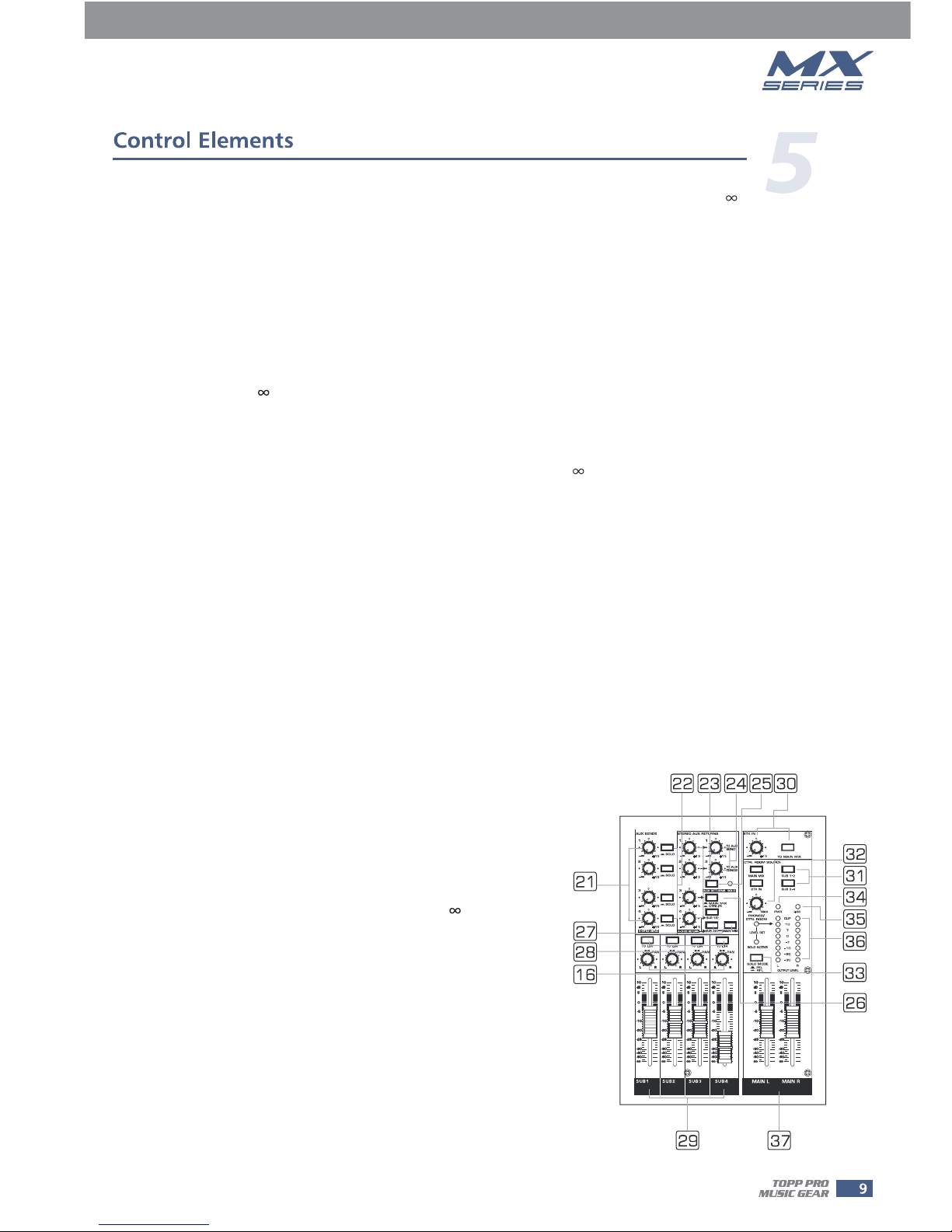
15- AUX SENDS Level Control
These four controls are used to adjust the level of the respective signal sent
to AUX bus, AUX1 and AUX2 can be switched to PRE/POST-FADER via the
PRE/POST button, so, generally, they can be used for monitor
This control gives you up to 15 dB boost or cut at 3 kHz. It is useful for
controlling voice. It can accurately polish your performance via adjusting
this knob.
This control gives you up to 15 dB boost or cut at 500 Hz.
If you turn this control up, you will boost all frequencies below 80 Hz.
You will give more punch to bass drum and bass guitar and make the
vocalist more "macho". Turn it down, you will cut all the frequencies
below 80 Hz. In this way, you can avoid low frequency vibrations and
resonance thus preserving the life of your woofers.
application and effects & sound processors input. AUX3 and AUX4 are
configured as POST-Faders. In this typical compact unit, excluding sending
out the signal directly to the external effect or processor equipment, AUX
SEND4 can also be assigned to the internal onboard effect module.
16- PAN/BAL Control
Abbreviation of PANORAMA control for mono channels, or the stereo channels, always says, BALANCE control.
Keep this control in center position, then the signal will be positioned in the middle of stage.
Each channel is equipped with a MUTE button. Pressing this button is equal to turning the fader down, which
can mute the corresponding channel output except for the channel INSERT send and SOLO (in PFL mode).
And the MUTE LED will illuminate.
Inside your MX2442, the audio signal is monitored in several different stages and then sent to the PEAK LED.
When the LED is red illuminated, it warns you that you are reaching signal saturation and possible distortion,
then you should reduce the input level for avoiding distortion.
17- PEAK LED
18- MUTE Button & LED
19- FADER
This fader will adjust the overall level of this channel and set the amount of signal send to the main output.
20- ASSIGNMENT Controls
Each channel provides four push-buttons: SUB1-2, SUB3-4, MAIN L-R and SOLO. Pressing the SOLO button, the
corresponding SOLO LED will illuminate and the SOLO signal will replace other signals send to the Headphone/
Control Room and Meters. Usually use the SOLO function in live work to preview channels before they are let
into the mix. It is useful to set an instrument's input level and EQ, and you can also solo any channel that you
want to. The SOLO switch never affects any mix other than the Control Room. The other three buttons can be
considered as signal assignment switches. Pressing the SUB1-2 will assign the channel signal to Subgroup1/2,
you can depend on the PAN switch to adjust the amount of channel signal sent to the SUB1versus SUB2, when
turns the PAN to completely left, then the signal can be only controlled by Subgroup1 and viceversa. In the
same way, pressing the SUB3-4 or MAIN L/R will assign the channel signal to Subgroup3/4 or MAIN MIX L/R,
and will also be affected by PAN.

23- Master STEREO AUX RETURNS Controls
These four controls set the level of effects that received from the stereo AUX RETURN connectors, which
can be varied from - to +15 dB. They are used to provide the further gain for low level effects.
24- TO AUX SEND1/2
The both rotary knobs assign the AUX RETURN signals to their respective AUX SEND outputs: The "TO AUX
SEND1" assign the signal from AUX RETURN1 to AUX SEND1 bus, and "TO AUX SEND2" assign the signal
from AUX RETURN2 to AUX SEND2 bus. The adjustable range goes from - to +15 dB.
AUX RETURN3 is equipped with the Main Mix & Ctrl/R button. Release the button to send the stereo
signal from AUX RETURN3 to MAIN MIX buses;
Engage the button, then the stereo signal will be sent to CTRL/R output.
26- MAIN MIX & CTRL/R Button
25- AUX RETURNS SOLO Button
The function of AUX RETURN SOLO is like the channel SOLO button. Engaging it sends the signal from
AUX RETURN (1-4) to the CTRL OUT, PHONES outputs and Meters display. It can also be affected by
SOLO mode button, and the LED next to the button will illuminate.
27- SUB1-2/SUB3-4/MAIN MIX Buttons
These three buttons are configured for AUX RETURN4, they can be regarded as the signal assignment
switches. When engaging the SUB1-2, the stereo signal from AUX RETURN4 will be assigned to
Subgroup1/2; in the same way, SUB3-4 for Subgroup3/4, MAIN MIX for MAIN MIX buses.
28- SUBGROUPS ASSIGN TO MAIN MIX
Through these switches, you can operate the subgroup faders as a master
control for assigning the subgroups to MAIN MIX. Engage the LEFT switch to
send the corresponding subgroup signal to MAIN MIX L, and the RIGHT
switch for MAIN MIX R. When engaging the both switches, the signal will be
sent to L/R of MAIN MIX.
21- Master AUX SENDS Controls
22- SOLO Button
These four controls are used to dete-rmine the master AUX SEND levels, which can be varied from - to
+15 dB. When the external effect units which connected to mixer, you
can get a further +15 dB gain available from these Aux Send outputs. As to the AUX4, it can also provide
the lovable level adjustment for the internal effect signal.
have no input gain control were
The function of these SOLO buttons are the same as the channel SOLO button, they can also be affected
by the SOLO MODE switch. Press the SOLO button, the corresponding AUX send will be routed to the Ctrl
Room/Phones outputs and Meters display.
29- SUBGROUPS Fader
These faders are used to control the levels of the signal send to the
SUB-GROUPS OUT, the adjustable range goes from - to +10 dB.
Any channel that is assigned to the subgroups, not muted and not
turned down will be assigned to the SUB OUTS.
30- 2TK LEVEL & TO MIX Button
By rotate the knobs, you can adjust the stereo signals level of 2TK
input and engaging the switch allows you to combine the 2-Track
output with the Main Mix. In other words, feeds the 2-Track In
signals into Main L/R output.

31- Control Room Source
NOTE: When any SOLO switch was engaged, the SOLO signal will replace other signals, and also be sent to
the Control Room, Phones and Meters.
32- PHONES/CTRL ROOM Controls
Rotate these knobs to adjust the stereo level of CTRL ROOM and PHONES outputs separately, which
can be varied from - to MAX.
You can choose to monitor any combination of MAIN MIX, SUB1-2, SUB 3-4 and 2TK IN via these Matrix
switches. Engaging these switches, the stereo signals will be delivered to the Phones, Control Room and
Meters display.
NOTE: The SOLO function can never affect the mix at main recording output, and also can't be affected
by channel's MUTE switch.
33- SOLO MODE Button
This button provides two modes: up for PFL (Pre-Fader-Listen) mode, down for AFL (After-Fader-Listen)
mode. Engage the button, the soloed signal will output after the Level control, otherwise, release the
button will output the
soloed signal before the Level control.
34- POWER LED
The LED indicates when the power is ON.
35- PHANTOM LED
This LED indicates when the phantom power is switched on.
36- LED Meter
The stereo 8-segment LED Meter will indicate the signal level send to the Ctrl Room and Phones outputs.
-TAPE IN
Use the Tape input if you wish to listen to your mix from a Tape Recorder or DAT.
- TAPE OUT
These RCA jacks will route the main mix into a tape recorder.
38- 2-TRACK IN/OUT
These jacks will be used to send the signal to a pair of
headphone or to powered studio monitors.
40- PHONES Jacks
39- USB LAMP socket
This lovable LAMP is very convenient for your operation,
it is located in the top right corner of the front panel,
and provides the 5V socket that can drive standard
USB-type lamp.
42- MAIN INSERT
These two 1/4" phone jacks are stereo insert points and used to connect processors such as compressors,
equalisers etc.. When insert a external processor into the jack, the Main stereo signal will be taken out
after the EQ and returned into the MAIN MIX output before the MAIN MIX fader.
41- MAIN MIX OUTPUT
These stereo outputs are supplied with both the XLR and 1/4" phone jacks
and it is controlled by the Main Mix Level.
37- MAIN MIX LEVEL Fader
This fader sets the amount of signal send either to the Main Mix Output or to the Tape Output.
B
PHONES
A
L
TAPE IN
R
TAPE OUT
2-TRACK IN OUT
INSERTINSERT
MAIN MIX
OUTPUT L
MAIN MIX
OUTPUT R
5V
0.5A
LAMP
BAL UNBAL BAL UNBAL
24-CH COMPACT INTEGRATED LIVE
SOUND MIXER
MX2442
12
3
12
3

AUX RETURNS
4CH12 CH11 CH9 CH8 CH7 CH6 CH5 CH4 CH3 CH2 CH1CH10
3
AUX SENDS
LL
43
RR
12
LL
12
RR
PHANTOMPOWER
DIRECT OUTS (BAL/UNBAL)
ON
OFF
USB
RECORD PLAY BACK
L
CTRL OUTMONO
R
(BAL/UNBAL)
+15
-
8
04
SUBGROUPS OUT
3
2
1
43
2
1
SUBGROUPS INSERT
SUB
1/2
CH
23/24
MAIN
MIX.
MAIN
MIX.
AC INPUT
100-240V 50/60Hz
RATED POWER CONSUMPTION: 60W
Fuse: T1.25AL AC250V
SERIAL
MODEL
MADE IN CHINA
Use only with a 250V fuse
MX2442
MX2442 MX2442
CH23/24


-12
EQ OFF
EQ ON
0
-8
-4
+8
+12
+4
63 500250125 2K
1K
-12
0
-8
-4
+12
+8
+4
16K
8K4K
STEREO GRAPHIC EQ
Note:MX2442 can simultaneously install two kinds of option modules. Two DSP modules can be
at same time installed together, while the EQ module and USB modules are not allowed to take
such operations.
9-band EQ module install
1- EQ Switch
2- STEREO GRAPHIC EQ
DSP module install
function
MX2442

PROGRAM (PUSH)
PEAK/MUTE DSP MUTE
DIGITAL STEREO EFFECTS PROCESSOR
24BITs
88
50-59 Flange Verb
60-69 Plate
70-79 Chorus GTR
80-89 Rotary GTR
90-99 Tremolo GTR
+
+
+
+
00-09 Vocal
10-19 Small Room
20-29 Large Hall
30-39 Echo
40-49 Echo Verb+
function
1- DISPLAY
It displays the selected preset.
2- PRESETS SELECTOR
3- DSP MUTE Switch & PEAK LED
Preset list for DSP effect

Optional USB Players Modules Section
This section can be selected and installed according to user's requirement. Please see installation
procedure. (USB Module lnstallation)
Option One - Song Module
The file system of USB memory for USB players is FAT16 and FAT32, and these players can only
decode Mp3. It has 7 rank subordinate folders at most.

5- Folder List:
See the Fig 3, the display shows MP3 files folders names. Use
PRE/ NEXT key to scan, press PLAY/PAUSE key, you'll
enter into corresponding folder. In order to return to Fig5
interface, you just need to press the STOP key.
Option Two - Track Module
The file system of USB memory for USB players is FAT16 and FAT32, and these players can only
decode Mp3. It has 7 rank subordinate folders at most.

8- DISPLAY:
All MP3 player information are monitored via this sexy & magic display.
-No selective mode
At normal state, there is no selective mode on the front panel, only a piece of panel without function.
-USB PLAYER selective mode
Please connect the 5PIN row-wire on the USB module to the CN16 header and 2 PIN row-wire to
CN 33 header on front panel. For Recording module, you also need to connect the 3 PIN row-wire
to CN 17 header to start recording function. Then fix the USB module on front panel with two screws.


Table of contents
Other Topp Music Gear Music Mixer manuals

Topp Music Gear
Topp Music Gear MX.22/2FX User manual

Topp Music Gear
Topp Music Gear MXi.1222CFX User manual

Topp Music Gear
Topp Music Gear MX1642 User manual

Topp Music Gear
Topp Music Gear MX series User manual

Topp Music Gear
Topp Music Gear TPM 4250 MKII User manual

Topp Music Gear
Topp Music Gear MXi.5 User manual

Topp Music Gear
Topp Music Gear DMX24.4 User manual

Topp Music Gear
Topp Music Gear TPM4200FX MKII V2 User manual

Topp Music Gear
Topp Music Gear MX.5 V2 User manual

Topp Music Gear
Topp Music Gear TPM8.2000 User manual