Topp Music Gear MXi.5 User manual

MXi SERIES MIXER
MXi.5, MXi.6/USB, MXi.10/USB, MXi.12/USB


3
Table of Contents
This device complies with Part 15 of the FCC Rules. Operation is subject to the following two
conditions: (1) this device may not cause harmful interference, and (2) this device must accept
any interference received, including interference that may cause undesired operation.
FCC Statement:
"This equipment has been tested and found to comply with the limits for a Class B digital device,
pursuant to part 15 of the FCC Rules. These limits are designed to provide reasonable protection
against harmful interference in a residential installation. This equipment generates, uses and can
radiate radio frequency energy and, if not installed and used in accordance with the instructions,
may cause harmful interference to radio communications. However, there is no guarantee that
interference will not occur in a particular installation. If this equipment does cause harmful
interference to radio or television reception, which can be determined by turning the equipment
off and on, the user is encouraged to try to correct the interference by one or more of the
following measures:
—Reorient or relocate the receiving antenna.
—Increase the separation between the equipment and receiver.
—Connect the equipment into an outlet on a circuit different from that to which the receiver is
connected.
—Consult the dealer or an experienced radio/TV technician for help."
1. Introduction
2. Features
3. Usefull Data
4. Hookup Diagram
5. Control Elements
6. Installation Tips
7. Wire Connections
8. Block Diagram
9. Technical Specifications
10. Guarantee
4
4
4
5
6
10
11
12
16
18

Introduction
Thank you for purchasing the MXi series mixing console. This series include several mixers (MXi.5
,MXi.6/USB, MXi.10/USB , MXi.12/USB ).
There is 2-band EQ on all mono channels (MXi.5), and 3-band EQ on mono channels, stereo
channels(MXi.6/USB, MXi.10/USB, MXi.12/USB), and built-in stereo USB / Audio interface
(MXi.6USB , MXi.10USB , MXi.12USB ). These mixers are really ideal for small club gigs.
Please read this manual carefully so you can take advantages of all the features of the MXi series.
Thank you again for making the right choice in purchasing the TOPP PRO MUSIC GEAR.
Features
Usefull Data
Please write your serial number here for future reference.
4
MXi.5
• 1 mono inputs with gold plated XLR and Balanced TRS jack
• 2 stereo inputs with Balanced TRS jack
• 2-band EQ on all mono channels
• 2-Track IN/OUT
• Balanced XLR & TRS jack output
MXi.6/USB , MXi.10/USB , MXi.12/USB
• 2 mono inputs (4 for MXi.12/USB ) with gold plated XLR and Balanced TRS jack
• 4 (2 for MXi.6/USB ) stereo inputs with Balanced TRS jack
• GAIN control and +48V phantom power for mono inputs
• 3-band EQ on all mono channels and stereo channels
plus 75Hz low cut filter on all mono channels (For MXi.10/USB & MXi.12/USB )
• 1 POST-fader AUX send for effect sends can be changed in PRE-fader for monitoring
• Peak LED in each channel
• 2-Track IN/OUT with discrete switches for routing to Control Room and to Main Mix
• Built-in stereo USB /Audio interface (For MXi.6USB , MXi.10USB , MXi.12USB )
Our Professional Audio Products are designed and tested by a highly qualified engineering team
with more than 20 years of experience. Great care is placed in delivering products with excellent
performance, specifications and dependable reliability. Also great emphasis is placed in creating
and bringing to market products that can fill multiple applications and also offer customers
exceptional value.
Every TOPP PRO audio product is strictly tested and complied to very strict standards.

5
Hookup Diagram 4

1- Mono MIC Input
The MXi series is equipped with one or more low-noise microphone
preamplifiers with optional phantom power providing up to 50dB of
amplification. You can connect almost any type of microphone.
Dynamic microphones do not need phantom power. Use phantom
power only with condenser microphones but make sure that the
phantom power switch is disengaged before connecting the
microphone. Phantom power will not damage your dynamic
microphones but it may damage tube or ribbon microphones so make
sure to read the microphone instructions manual before engaging
phantom power switch. There are also equipped with 1/4" TRS
balanced and TS unbalanced LINE IN plug, you can connect with
line-level instruments, such as synthesizers, keyboards, drum machines
or effect devices.
NOTE: Never try to connect a line-level signal to the XLR MIC input
when the phantom power is engaged, doing this you may seriously
damage your equipment.
2- LINE INPUTS
They are organized in stereo pair and provided with 1/4" TRS sockets.
It is used to connect the stereo device, plug both the left input and the
right input. Using the left input if connect a mono input signal to the
STEREO INPUT, the signal will appear on both sides.
3- GAIN CONTROL
This GAIN control is used to control the input sensitivity of the MIC and
LINE inputs. The adjustable range goes from 0 dB to 50dB.
EQUALIZATION
The MXi series has 3-band EQ on all mono channels(except MXi.5 has
2-band EQ). And only MXi.6/USB has EQ controls on stereo channels.
All bands provide up to 15 dB boost or cut.
4- HIGH
This is the treble control. You can use it to get rid of high frequency of
the human voice. The gain range goes from -15 dB to +15 dB with a
centre frequency of 12 kHz.
5- MID EQ (except MXi.5 )
This control provides 15 dB boost or cut at 2.5 kHz. It can affect most
fundamental frequencies of all musical instruments and human voice.
6- LOW EQ
This is the bass control. It is used to boost male voice, kick-drum or
bass guitar. Your system will sound much bigger than what it is. The
gain range goes from -15 dB to +15 dB and the center frequency is 80
Hz.
6
Control Elements
5

7- 75 Hz Low-Cut Switch (MXi.10/USB , MXi.12/USB only)
By pressing this button you will activate a 75Hz low frequency filter
that cuts the bass frequency below 75Hz. You can use this switch to
reduce the hum noise caused by the mains power supply, or the stage
rumble while using a microphone.
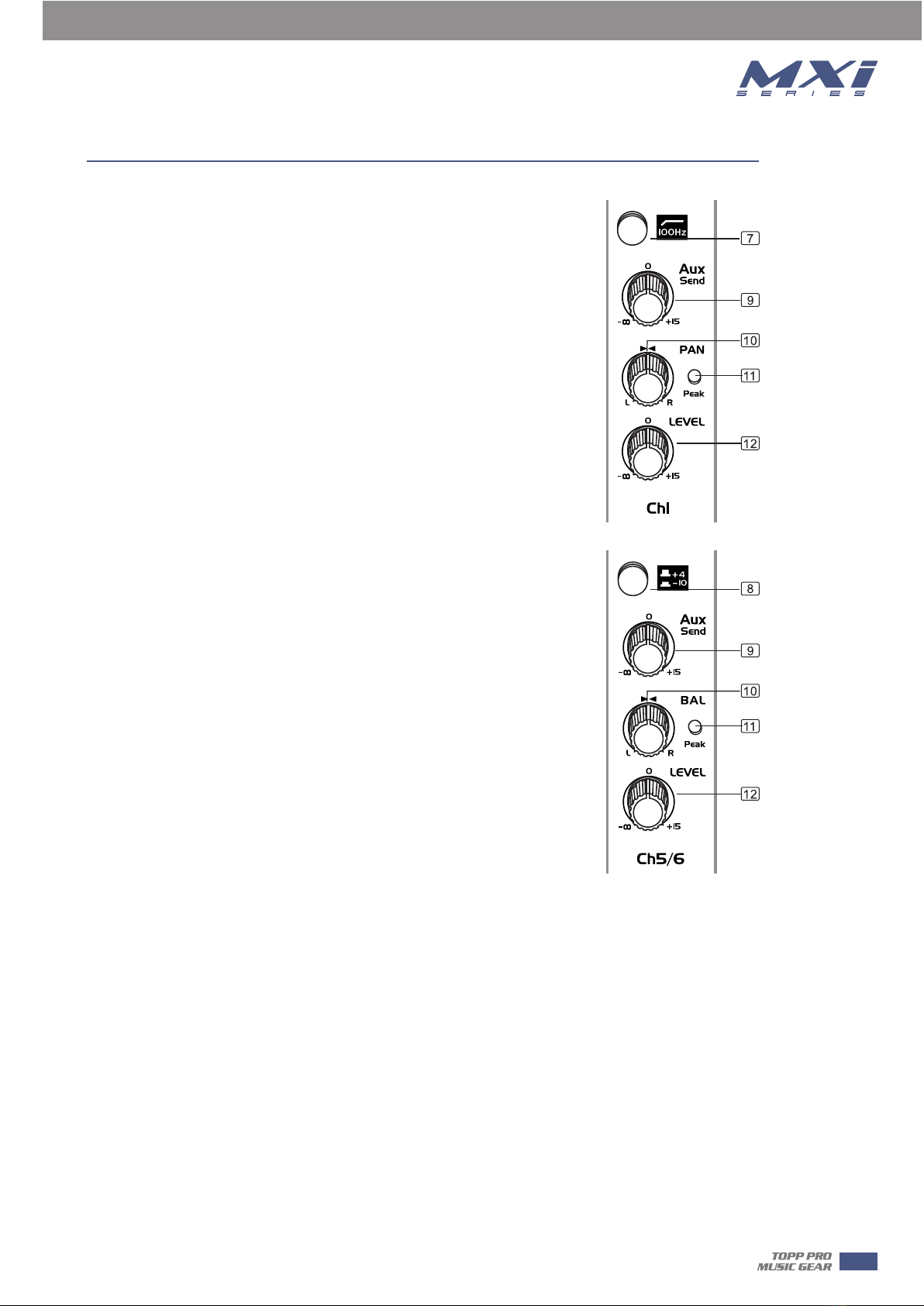
8- +4/-10 Switch (MXi.10/USB , MXi.12/USB only)
These switches are used to select the input sensitivity of the line inputs
on the stereo channels. +4 dBu is suitable for professional audio
devices and -10dBu is suitable for general devices. If not sure to use
which setting, try +4 dBu first, then change it to -10dBu if the volume
is too small to be satisfied.
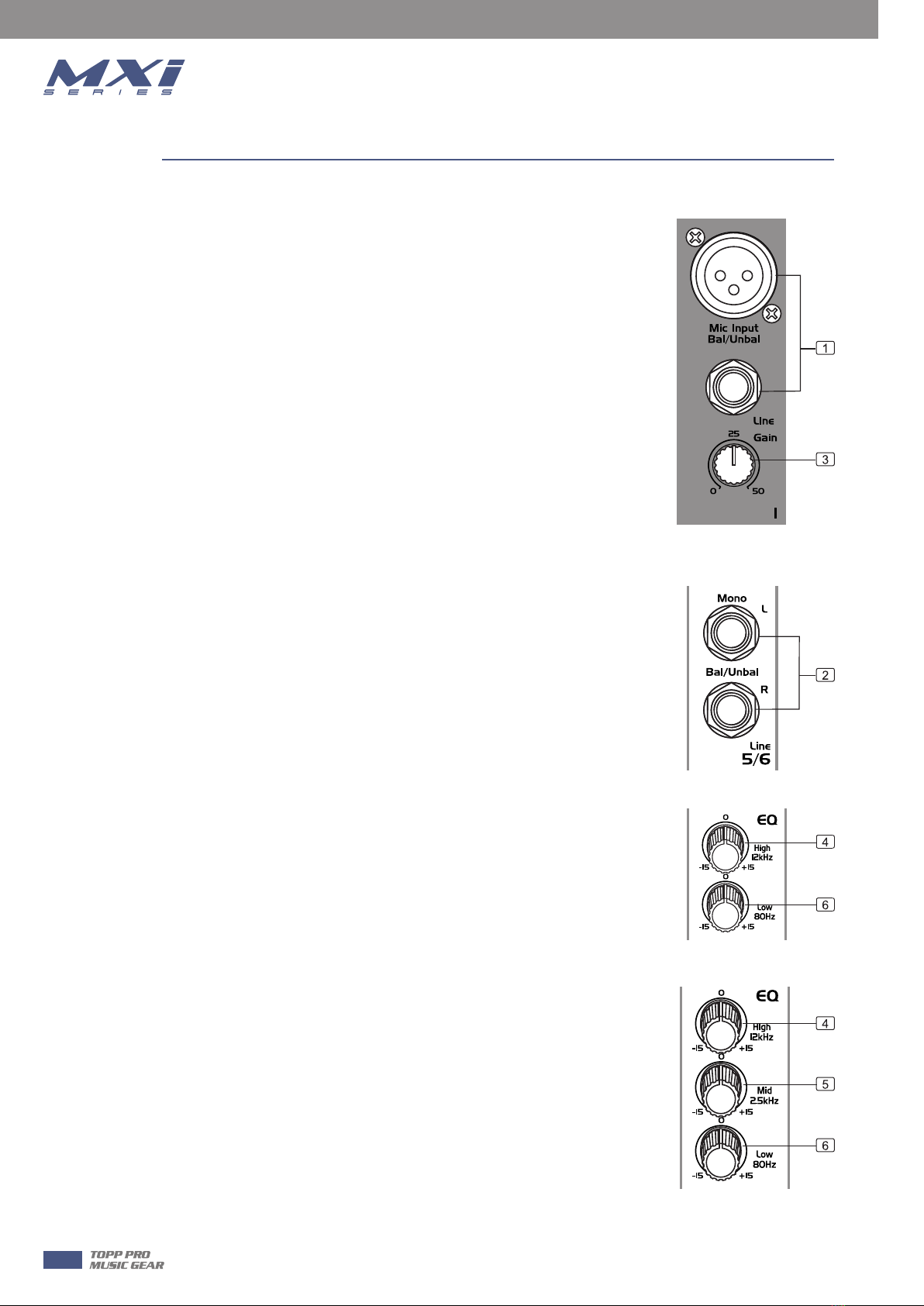
9- AUX Send (except MXi.5 )
This control is used to feed the mono input of parallel effects devices
or the input of a stage monitor amplifier via the AUX SEND output jack.
All the channel controls (except PAN or BAL) will affect the AUX signal.
The signal is tapped off after the LEVEL control. The output from an
external processor can come back via STEREO AUX RETURN inputs (on
the MXi.6/USB ) or stereo channel (MXi.10/USB ,MXi.12/USB ), and be
added to the main mix.
10- PAN/BAL
Abbreviation of PANORAMA control for mono channels, for the stereo
channels, always says, BALANCE control. You can adjust the stereo
image of the signal via this control. For mono MIC/LINE channels, keep
PAN control in centre position and your signal will be positioned in the
middle of stage that is to say the mono signal appears equally in both
sides. Turn this control fully counterclockwise and the signal will be
present only on the left speaker and vice-versa. For stereo channels, by
rotating the BAL control, you can attenuate the signal of left or right.
It means if turn the control to left, the right channel will be attenuated;
if turned to right, the left channel will be attenuated.
11- PEAK LED
When this LED blinks, it warns you that you are reaching signal saturation and possible distortion.
From this LED you can adjust the correct level, not too strong to cause distortion and not too
weak to be lost in noise.
12- LEVEL
This control will adjust the overall level of this channel. If you set the LEVEL control in max, it's
usually a sign that your GAIN is set too low. If set the LEVEL control in min, your GAIN may be too
high.
13- CD/TAPE INPUTS
Use the Tape Input if you wish to listen to your mixer from a Taper Recorder or DAT. When the
TAPE TO MIX switch is pushed in, the signal coming from Taper Recorder will assign to main mix;
when the CD/TAPE switch which on the front panel is engaged in the signal can also be assigned
to the CONTROL ROOM/PHONES outputs. If you connect a mono device, you will need a
"Y-splitter" RCA adapter.
7
Control Elements 5

14- TAPE OUTPUTS
These RCA jacks will assign the main out signal to a tape recorder or DAT. The TAPE OUT level is
affected by MAIN MIX control.
15- TAPE/USB TO MIX Switch(USB For MXi.6USB , MXi.10USB , MXi.12USB )
Connect a CD or Tape Deck to the CD/TAPE inputs, and push down this switch to add the CD/TAPE
signal or USB Audio interface signal (MXi.6USB , MXi.10USB , MXi.12USB ) to the main mix. The
volume level is controlled by MAIN MIX control.
16- TAPE TO CTRL RM/PHONES Switch (TAPE TO PHONES on MXi.5 )
Switch is used to select the signal source for the CONTROL ROOM outputs, PHONES, and METERS.
Release this switch, they all receive the main mix signal tapped after the MAIN MIX control.
Engage this switch, they all receive the CD/TAPE Input signal. Turn down the CTRL ROOM/PHONES
control (just PHONES on the MXi.5 ) before engaging.
17- AUX TO CTRL RM / PHONES Switch ( MXi.10/USB , MXi.12/USB only)
Engage this switch to monitor the aux send signal in the Control Room/Phones outputs.
18- CTRL ROOM/PHONES Control (PHONES control on the MXi.5 )
This control is used to adjust the signal level going to the CONTROL ROOM/PHONES outputs. And
it won't affect the Main Mix output.
19- MASTER AUX SEND Control (except MXi.5 )
This knob is used to determine the master AUX SEND levels. The adjustable range is from -∞ to
+15 dB. When the external effect unit connected to mixer has no input gain control, you can get
a further +15 dB gain available from these AUX SEND outputs.
20- POWER LED
This LED lights up when the power switch is turned on.
21- PHANTOM 48V Switch and LED(+18V on MXi.5 )
This +48V DC Phantom Power switch only apply to the XLR microphone inputs. Never connect
microphones when the phantom power is on already. The LED near to this switch will light up
when the phantom power is switched on.
NOTE: Turn down all output levels before operating this switch to avoid the possibility of "pop" in
your speakers. Do not use phantom power with tube or ribbon microphones, as this may cause
damage.
Control Elements
8
5

22- METERS
This stereo LED meter will indicate the level of the overall output
signal.
23- MAIN MIX
This control sets the level of main mix signals sent to the Main
Outputs, Tape Outputs, CONTROL ROOM, PHONES, and LED
Display. On the MXi.5 and MXi.6/USB , this is a rotary control;
on the MXi.10/USB and MXi.12/USB , this is a fader.
Note: When connecting a speaker to the speaker output jacks,
please pay more attention to the level setting for avoiding
damaging the speaker. Generally speaking, the faders will be
positioned between 0 dB and the +5 dB.
24- MAIN OUT
These 1/4" TRS jacks represent the end of the mixer chain, where
your fully mixed stereo signal enters the real world. Connect
these outputs to the inputs of your amplifiers, powered
speakers, or serial effects processor (graphic equalizer, for
example).
25- CTRL ROOM OUT
These 1/4" TRS are used to assign the control room signal to the
studio monitor speakers. They can also be used to provide
another main mix output, or to monitor the CD/TAPE Inputs
(when engage the TAPE TO CTRL RM/PHONES switch), or to
monitor the aux send signal (MXi.10/USB, MXi.12/USB only
with FX TO CTRL ROOM switch is engaged).
26- AUX SEND OUT
These 1/4" TRS are used to send out the signal from the AUX bus
to external device such as effects equipment. Each channel has
an AUX SEND control knob that adjusts how much of that
channel's signal appear at each of the output. This output is
affected by the channel LEVEL, but not MAIN MIX control.
27- PHONES OUTPUT
This jack is used to send out the mix signal to a pair of
headphones, and the signal is the same as the CTRL RM OUTS
outputs. The level is controlled by the CTRL ROOM/PHONES
knob. You can listen to the Main Mix, the CD/TAPE, or the AUX
SEND (MXi.10/USB , MXi.12/USB ) depending upon the position
of the TAPE TO CTRL RM/PHONES switch and FX TO CTRL ROOM
switch.
Control Elements
9
5

Rear Panel
28- POWER IN
This connection is where you connect the supplied external AC power supply to provide AC power
to the mixer. Connect the external power supply to your mixer first, then plug the power supply
into a suitable and properly rated AC outlet.
29- POWER SWITCH
This switch is used to turn the main power ON and OFF.
30- USB PORT
This Type B USB port can be used to connect the computer via Type B to A connector.
1- Speakers should be placed in a position that allows for unobstructed sound projection. In
many instances is beneficial for speakers to be elevated on tripod stands to achieve maximum
dispersion and reach.
2- Use professional advice or service when hanging and installing speakers. Please take
precautions to secure them to prevent them from falling and hurting someone. Care should be
taken as to not damage the cabinet or its components. Please comply with all pertinent
Regulations.
3- Use quality cables. Using quality cables will ensure the best possible sound.
4- For best results match the speakers to a good amplifier that matches the wattage and
impedance of your speakers. Proper amplification power results in good quality audio and
longer component life. Check out the power requirement for your cabinet.
5- Avoid pointing a microphone directly at an amplified speaker doing so, could cause feedback
possibly damaging speaker components and your hearing.
Control Elements
10
5
Installation Tips
6
Enjoy the sound!

Wire Connections
11
7

Block Diagram
12
8
MXi.5

Block Diagram
13
8
MXi.6/USB

14
8Block Diagram
MXi.10/USB

15
8
Block Diagram
MXi.12/USB

Technical Specifications
16
9
MXi SERIES MIXER MXi.5 MXi.6/USB MXi.10/USB MXi.12/USB

Technical Specifications
17
9
MXi SERIES MIXER MXi.5 MXi.6/USB MXi.10/USB MXi.12/USB

18
10 Guarantee


Mezcladores Serie MXi
MXi.5, MXi.6/USB, MXi.10/USB, MXi.12/USB
This manual suits for next models
4
Table of contents
Other Topp Music Gear Music Mixer manuals

Topp Music Gear
Topp Music Gear MX1642 User manual

Topp Music Gear
Topp Music Gear MX.22/2FX User manual

Topp Music Gear
Topp Music Gear TPM8.2000 User manual

Topp Music Gear
Topp Music Gear MX series User manual

Topp Music Gear
Topp Music Gear MXI Series User manual

Topp Music Gear
Topp Music Gear TPM4200FX MKII V2 User manual

Topp Music Gear
Topp Music Gear DMX24.4 User manual

Topp Music Gear
Topp Music Gear MX.5 V2 User manual

Topp Music Gear
Topp Music Gear MXi.1222CFX User manual

Topp Music Gear
Topp Music Gear TPM 4250 MKII User manual