TOPP RR Operating and maintenance manual

ISTRUZIONI PER L’INSTALLAZIONE E L'USO
COD. 8P5014
IT
UNITÀ DI ALIMENTAZIONE E COMANDO MOTORI 230V ~
POWER UNIT AND 230V~ MOTOR DRIVER
RR
VER 0.0
REV 11.17
INSTALLATION AND USE INSTRUCTIONS
EN
IT
DICHIARAZIONE DI CONFORMITÀ / DECLARATION OF CONFORMITY
1
2RR
Il sottoscritto in nome e per conto di / The undersigned, in the name of and behalf of the
following company:
Topp S.r.l.
Via Galvani, 59
36066 Sandrigo (VI)
Italia
dichiara che l’apparecchio elettrico denominato / declares that the electrical device called:
UNITÀ DI ALIMENTAZIONE E COMANDO ATTUATORI 230V
per automazioni finestre
POWER UNIT AND 230V~ MOTOR DRIVER
for windows automation
Modello / Model: RR
è conforme alle seguenti direttive (incluse tutte le revisioni applicabili)/
is in compliance with the following directives (including all applicable amendments):
Direttiva Apparecchiature Radio 2014/53/UE: Attuazione Italiana DLgs. 22 giugno 2016, n.128
Radio Equipment Directive (RED) 2014/53/EU
Direttiva Rohs II 2011/65/UE: Attuazione Italiana DLgs. 4 marzo 2014, n.27
Rohs II Directive 2011/65/EU
e inoltre dichiara che sono state applicate le seguenti norme armonizzate: /
and also declares that the following harmonised standards have been applied:
EN 50581:2012
EN 300 220-2 V3.1.1
e i seguenti documenti tecnici /
and the following technical documents:
EN 60335-1:2012 + AC:2014 + A11:2014
EN 62233:2008
EN 55014-1:2006 + A1:2009 + A2:2011
EN 55014-2:2015
EN 61000-6-2:2005
EN 61000-6-3:2007 + A1:2011 + AC:2012
EN 61000-3-2:2014
EN 61000-3-3:2013
EN 301 489-3 V1.6.1
La presente dichiarazione di conformità è rilasciata sotto la responsabilità esclusiva del
fabbricante. / This declaration of conformity is issued under the sole responsibility of the
manufacturer.
Firma / Signature: .............................................................
Amministratore / Administrator Matteo Cavalcante
Data / Date : Sandrigo, 12/06/2017
ORIGINALE
ORIGINAL

IT
1 - DICHIARAZIONE DI CONFORMITÀ . . . . . . . . . . . . . . . . . . . . . . . . . . . . . . . . . . . . . . . . . . . . . . . pag 02
2 - GENERALITÀ . . . . . . . . . . . . . . . . . . . . . . . . . . . . . . . . . . . . . . . . . . . . . . . . . . . . . . . . . . . . . . . . . . . pag 04
2.1 - Avvertenze generali . . . . . . . . . . . . . . . . . . . . . . . . . . . . . . . . . . . . . . . . . . . . . . . . . . . . . . . . . . . pag 04
2.2 - L’installatore . . . . . . . . . . . . . . . . . . . . . . . . . . . . . . . . . . . . . . . . . . . . . . . . . . . . . . . . . . . . . . . . . pag 04
2.3 - L’utilizzatore . . . . . . . . . . . . . . . . . . . . . . . . . . . . . . . . . . . . . . . . . . . . . . . . . . . . . . . . . . . . . . . . . pag 04
2.4 - Campi di applicazione. . . . . . . . . . . . . . . . . . . . . . . . . . . . . . . . . . . . . . . . . . . . . . . . . . . . . . . . . . pag 04
2.5 - Garanzia. . . . . . . . . . . . . . . . . . . . . . . . . . . . . . . . . . . . . . . . . . . . . . . . . . . . . . . . . . . . . . . . . . . . pag 04
2.6 - Assistenza tecnica . . . . . . . . . . . . . . . . . . . . . . . . . . . . . . . . . . . . . . . . . . . . . . . . . . . . . . . . . . . . pag 04
2.7 - Confezione . . . . . . . . . . . . . . . . . . . . . . . . . . . . . . . . . . . . . . . . . . . . . . . . . . . . . . . . . . . . . . . . . . pag 04
3 - DESCRIZIONE TECNICA . . . . . . . . . . . . . . . . . . . . . . . . . . . . . . . . . . . . . . . . . . . . . . . . . . . . . . . . . pag 04
3.1 - Targa dati e marcatura “CE” . . . . . . . . . . . . . . . . . . . . . . . . . . . . . . . . . . . . . . . . . . . . . . . . . . . . . pag 04
3.2 - Dati tecnici . . . . . . . . . . . . . . . . . . . . . . . . . . . . . . . . . . . . . . . . . . . . . . . . . . . . . . . . . . . . . . . . . . pag 05
3.3 - Denominazione dei componenti e dimensioni . . . . . . . . . . . . . . . . . . . . . . . . . . . . . . . . . . . . . . . . pag 05
3.4 - Descrizione tecnica e di funzionamento . . . . . . . . . . . . . . . . . . . . . . . . . . . . . . . . . . . . . . . . . . . . pag 05
4 - SICUREZZA . . . . . . . . . . . . . . . . . . . . . . . . . . . . . . . . . . . . . . . . . . . . . . . . . . . . . . . . . . . . . . . . . . . . pag 06
4.1 - Avvertenze generali . . . . . . . . . . . . . . . . . . . . . . . . . . . . . . . . . . . . . . . . . . . . . . . . . . . . . . . . . . . pag 06
4.2 - Dispositivi di protezione . . . . . . . . . . . . . . . . . . . . . . . . . . . . . . . . . . . . . . . . . . . . . . . . . . . . . . . . pag 06
4.3 - Targhe relative alla sicurezza . . . . . . . . . . . . . . . . . . . . . . . . . . . . . . . . . . . . . . . . . . . . . . . . . . . . pag 06
4.4 - Rischi residui . . . . . . . . . . . . . . . . . . . . . . . . . . . . . . . . . . . . . . . . . . . . . . . . . . . . . . . . . . . . . . . . pag 06
5 - INSTALLAZIONE . . . . . . . . . . . . . . . . . . . . . . . . . . . . . . . . . . . . . . . . . . . . . . . . . . . . . . . . . . . . . . . . pag 06
5.1 - Avvertenze generali . . . . . . . . . . . . . . . . . . . . . . . . . . . . . . . . . . . . . . . . . . . . . . . . . . . . . . . . . . . pag 06
5.2 - Installazione del sensore pioggia . . . . . . . . . . . . . . . . . . . . . . . . . . . . . . . . . . . . . . . . . . . . . . . . . pag 07
5.3 - Installazione della centrale . . . . . . . . . . . . . . . . . . . . . . . . . . . . . . . . . . . . . . . . . . . . . . . . . . . . . . pag 07
5.4 - Collegamento elettrico . . . . . . . . . . . . . . . . . . . . . . . . . . . . . . . . . . . . . . . . . . . . . . . . . . . . . . . . . pag 07
6 - USO E FUNZIONAMENTO. . . . . . . . . . . . . . . . . . . . . . . . . . . . . . . . . . . . . . . . . . . . . . . . . . . . . . . . . pag 07
6.1 - Avvertenze generali . . . . . . . . . . . . . . . . . . . . . . . . . . . . . . . . . . . . . . . . . . . . . . . . . . . . . . . . . . . pag 07
6.2 - Programmazione dei dip-switch . . . . . . . . . . . . . . . . . . . . . . . . . . . . . . . . . . . . . . . . . . . . . . . . . . pag 08
6.3 - Led . . . . . . . . . . . . . . . . . . . . . . . . . . . . . . . . . . . . . . . . . . . . . . . . . . . . . . . . . . . . . . . . . . . . . . . . pag 08
6.4 - Radiocomando TR8 . . . . . . . . . . . . . . . . . . . . . . . . . . . . . . . . . . . . . . . . . . . . . . . . . . . . . . . . . . . pag 08
6.5 - Reset della centrale . . . . . . . . . . . . . . . . . . . . . . . . . . . . . . . . . . . . . . . . . . . . . . . . . . . . . . . . . . . pag 08
6.6 - Programmazione del radiocomando . . . . . . . . . . . . . . . . . . . . . . . . . . . . . . . . . . . . . . . . . . . . . . . pag 08
6.7 - Uso del radiocomando . . . . . . . . . . . . . . . . . . . . . . . . . . . . . . . . . . . . . . . . . . . . . . . . . . . . . . . . . pag 09
6.8 - Portata del radiocomando. . . . . . . . . . . . . . . . . . . . . . . . . . . . . . . . . . . . . . . . . . . . . . . . . . . . . . . pag 09
7 - APPENDICE . . . . . . . . . . . . . . . . . . . . . . . . . . . . . . . . . . . . . . . . . . . . . . . . . . . . . . . . . . . . . . . . . . . . pag 09
7.1 - Manutenzione. . . . . . . . . . . . . . . . . . . . . . . . . . . . . . . . . . . . . . . . . . . . . . . . . . . . . . . . . . . . . . . . pag 09
7.2 - Demolizione . . . . . . . . . . . . . . . . . . . . . . . . . . . . . . . . . . . . . . . . . . . . . . . . . . . . . . . . . . . . . . . . . pag 09
7.3 - Accessori e ricambi . . . . . . . . . . . . . . . . . . . . . . . . . . . . . . . . . . . . . . . . . . . . . . . . . . . . . . . . . . . . pag 10
8 - FIGURE . . . . . . . . . . . . . . . . . . . . . . . . . . . . . . . . . . . . . . . . . . . . . . . . . . . . . . . . . . . . . . . . . . . . . . . . pag 18
INDICE
3
IT
ISTRUZIONI PER L’INSTALLAZIONE E L’USO
RR
IT
Per l’assistenza contattare il rivenditore di fiducia o il
fabbricante.
La garanzia dell’apparecchio decade qualora l’impiego dello
stesso non sia conforme alle istruzioni e norme riportate nel
presente manuale e qualora vengano utilizzati componenti,
accessori, ricambi e sistemi di comando non originali (vedi
pag.23)
Ogni confezione standard (Fig.1) contiene:
1. N.1 Involucro inferiore
2. N.1 Involucro superiore
3. N.1 Scheda RR 230V
4. N° 2 Viti autofilettanti d2,9x13
5. N°1 cavo speciale per collegamento pulsante (deviatore)
manuale.
Assicurarsi che i componenti sopra descritti siano presenti
all’interno della confezione e che l’apparecchio non abbia
subito danni durante il trasporto. Qualora si riscontrassero
delle anomalie è vietato installare l’unità di alimentazione ed
è obbligatorio richiedere l’assistenza tecnica del rivenditore
di fiducia o del fabbricante.
L’unità di alimentazione è stata progettata e realizzata
esclusivamente per alimentare e comandare motori
“ORIGINALI TOPP 230V~” per serramenti ed è
assolutamente vietato qualsiasi altro tipo di impiego e
utilizzo del prodotto se non autorizzato da TOPP.
&L’unità di alimentazione deve essere collocata all’interno
del locale in una posizione idonea e in funzione della distanza
dei motori da comandare nel rispetto delle condizioni di
sicurezza previste dalla legislazione vigente nel paese di
utilizzazione.
&E’ assolutamente vietato installare l’unità di alimentazione
sulla parte esterna del locale soggetto agli agenti atmosferici.
&E’ assolutamente vietata la messa in servizio dell’unità di
alimentazione in ambienti con atmosfera potenzialmente
esplosiva.
CAMPI D’APPLICAZIONE
ASSISTENZA TECNICA
con la centralina in manutenzione per effettuare semplici
operazioni di manutenzione ordinaria (pulizia).
L’utilizzatore non deve eseguire operazioni riservate ai
manutentori o ai tecnici specializzati. Il costruttore non
risponde dei danni derivati dalla mancata osservanza di
questo divieto.
targhetta adesiva in poliestere, serigrafata colore nero che
viene applicata esternamente sull’apparecchio. Nella
targhetta sono indicati in modo leggibile ed indelebile i
seguenti dati:
Prima di installare e utilizzare l’apparecchio è
obbligatorio che l’installatore e l’utilizzatore leggano e
comprendano in tutte le sue parti il presente manuale.
&Il presente manuale è parte integrante dell’unità di
alimentazione e deve obbligatoriamente essere conservato
dall’installatore, assieme a tutta la documentazione allegata,
per futuri riferimenti.
&Il presente manuale è destinato al proprietario, agli
utilizzatori, agli installatori e ai tecnici abilitati alla
manutenzione, ed ha lo scopo lo scopo di fornire tutte le
informazioni necessarie affinché, oltre ad un corretto utilizzo
dell’unità di alimentazione, sia possibile gestire la stessa nel
modo più sicuro e autonomo possibile.
&Il presente manuale è stato redatto da TOPP srl che ne
riserva tutti i diritti d’autore. Nessuna parte dello stesso deve,
quindi, essere riprodotta o diffusa senza l’autorizzazione
scritta da parte del fabbricante.
&TOPP srl si riserva il diritto di modificare e migliorare il
manuale e i prodotti descritti in qualsiasi momento e senza
obbligo di preavviso.
&I dati riportati nel presente manuale sono stati redatti e
controllati con la massima cura; tuttavia TOPP srl declina
ogni responsabilità per possibili inesattezze dovute ad
eventuali omissioni o a errori di stampa o di trascrizione.
IT
GENERALITÀ
2
2.1
AVVERTENZE GENERALI
L’installazione, la messa in funzione e gli interventi di
manutenzione dell’unità di comando devono essere
eseguiti esclusivamente da personale tecnico
specializzato in possesso dei requisiti tecnico-
professionali previsti dalla legislazione vigente nel
paese di installazione.
Il tecnico specializzato elettricista deve essere in grado di
installare l’unità di comando, di metterla in opera e di farla
funzionare in “manutenzione”; è abilitato a tutti gli interventi di
natura elettrica e meccanica di regolazione e di manutenzione
e deve essere in grado di operare in presenza di tensioni
all’interno di armadi elettrici e scatole di derivazione.
2.2
INSTALLAZIONE
2.3
UTILIZZATORE
2.4
2.5
GARANZIA
2.6
2.7
CONFEZIONE
IT
DESCRIZIONE TECNICA
3
3.1
TARGA DATI E MARCATURA “CE”
L’utilizzazione dell’apparecchio può essere eseguita
esclusivamente da un utilizzatore che agisca in conformità
delle istruzioni riportate nel presente manuale.
L’utilizzatore deve essere in grado di comandare l’unità di
alimentazione in condizioni normali attraverso l’uso dei
comandi preposti. Deve inoltre essere in grado di operare
La marcatura “CE” attesta la conformità della RR ai requisiti
essenziali di sicurezza e di salute previsti dalle Direttive
Europee di prodotto. Tale marcatura è costituita da una
4
ISTRUZIONI PER L’INSTALLAZIONE E L’USO
IT RR
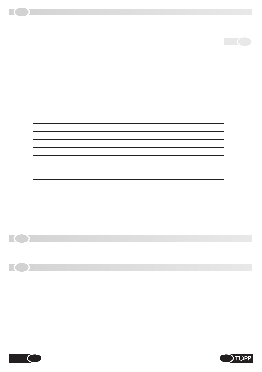
Nella Tab. 1 sono riportati i dati tecnici che caratterizzano l’apparecchio.
TENSIONE DI ALIMENTAZIONE
TENSIONE DI USCITA
POTENZA ASSORBITA A VUOTO
SERVIZIO
PREDISPOSIZIONE AL COLLEGAMENTO
AI DISPOSITIVI ESTERNI
DOPPIO ISOLAMENTO ELETTRICO
TEMPERATURA DI FUNZIONAMENTO
DIMENSIONI
PESO LORDO
ATTUATORI C20 230V COLLEGABILI
230V - 50Hz
230V - 50Hz
2W
In funzione dei motori collegati
Sensore pioggia o
comando manuale via cavo
Sì
-5°C ÷ +50°C
87x53x32mm
100 g
N. 6
Tab. 1
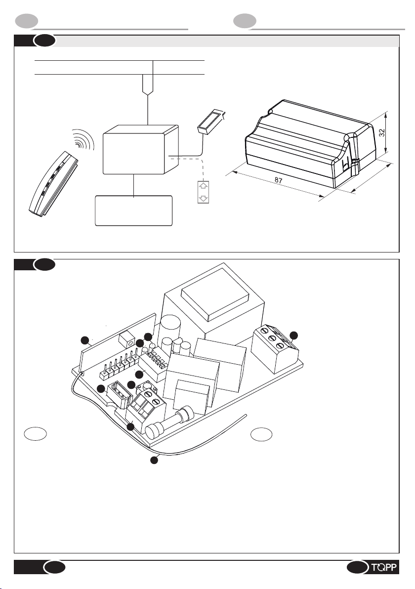
Nelle Fig. 4a e Fig.4b sono rappresentati e denominati i componenti principali che costituiscono la centrale RR.
CORRENTE MASSIMA DI USCITA
1,3 A
ATTUATORI C30 230V COLLEGABILI
N. 4
ATTUATORI C40 230V COLLEGABILI
N. 5
ATTUATORI ACK4 230V COLLEGABILI
N. 4
ATTUATORI T50 230V COLLEGABILI
N. 4
ATTUATORI T80 230V COLLEGABILI
N. 3
ATTUATORI SL60 230V COLLEGABILI
N. 4
ATTUATORI C240 230V COLLEGABILI
N. 3
L'unità di comando RR è stata progettata e realizzata per
comandare un attuatore 230V ~ in modo manuale attraverso
il radiocomando TR8 (la cui programmazione e utilizzo sono
trattati nel par.6.4 e seguenti) o automatico attraverso il
sensore pioggia ad essa collegato.
@Per il funzionamento manuale, in alternativa al
radiocomando, è possibile collegare all’ingresso J1 della
centralina (attraverso un cavo speciale fornito su
richiesta da Topp), un pulsante deviatore con posizione
“0” centrale con comando di tipo uomo presente (ved.
schema di collegamento di Fig.9) il quale andrà a
comandare l’attuatore collegato. Questa soluzione,
tuttavia, non permette l’installazione del sensore pioggia.
Il funzionamento automatico segue una logica predefinita.
Quando piove, il sensore pioggia collegato all’ingresso J1
(vedi schema di collegamento di Fig.8) invia alla centrale il
comando di chiusura automatico del motore collegato.
E' comunque consentita la riapertura forzata manuale anche
con sensore pioggia attivo. Trascorsi 10 minuti dal comando
di apertura forzata, se il sensore è ancora attivo le finestre si
chiudono, se non è attivo rimangono aperte.
La centrale RR ha diverse modalità di funzionamento le quali
possono essere impostate attraverso la programmazione di
microinterruttori denominati dip-switch (par.6.2). Mediante il
tasto SP1 è possibile programmare i radiocomandi mentre,
attraverso i led di colore rosso e verde (par.6.3), è possibile
monitorare lo stato dell'unità di comando.
3.2
DATI TECNICI
3.3
DENOMINAZIONE DEI COMPONENTI E DIMENSIONE
3.4
INFORMAZIONI TECNICHE E DI FUNZIONAMENTO
5
IT
ISTRUZIONI PER L’INSTALLAZIONE E L’USO
RR
%Il logo del fabbricante
%La marcature “CE”
%Il simbolo del doppio isolamento elettrico
%Il simbolo della Direttiva “RAEE” 2002/96/CE
%Il tipo e il modello
%La tensione (V) e la frequenza (Hz) di alimentazione elettrica
%La tensione (V) e la frequenza (Hz) di uscita
%La corrente (A) massima di uscita
%Il grado di protezione IP
%La versione

&Il personale operativo deve essere messo al corrente sui
rischi di incidente, sui dispositivi di sicurezza per gli operatori,
le norme generali di prevenzione degli incidenti previste dalle
direttive internazionali e dalla legge vigente nel paese di
utilizzo dell’unità di alimentazione. Il comportamento del
personale operativo deve in ogni caso rispettare
scrupolosamente le norme sulla prevenzione degli incidenti
vigenti nel paese di utilizzo dell’unità stessa.
&Nel caso in cui il serramento sia accessibile o installato ad
una altezza da terra minore di 2,5 m, nell’eventualità possa
essere comandato da personale utilizzatore non addestrato
o da comando remoto, dotare il sistema di un arresto di
emergenza che intervenga automaticamente per evitare il
rischio di schiacciamento o di trascinamento del corpo
inserito tra la parte mobile e la parte fissa del serramento
stesso.
&È assolutamente vietato rimuovere o alterare le targhe
apposte dal costruttore sull’unità di alimentazione.
&Questo apparecchio non è adatto all’uso da parte di
persone (inclusi bambini) con capacità fisiche, sensoriali e
mentali ridotte o inesperte, a meno che non vengano
supervisionate ed istruite nell’uso dell’apparecchio da una
persona responsabile per la loro sicurezza. I bambini devono
essere controllati per assicurarsi che non giochino con
l’apparecchio.
Protezione contro il pericolo elettrico: L’unità di
alimentazione è protetta contro il pericolo elettrico da contatti
diretti e indiretti.
Le misure di protezione contro i contatti diretti hanno lo scopo
di proteggere le persone dai pericoli derivanti dal contatto
con parti attive normalmente in tensione. Le misure di
protezione contro i contatti indiretti, invece, hanno lo scopo di
proteggere le persone dai pericoli derivanti dal contatto con
parti conduttrici, normalmente isolate, le quali potrebbero
andare in tensione a causa di guasti (cedimento
dell’isolante).
Le misure di protezione adottate sono le seguenti:
1. isolamento delle parti attive con un corpo in materiale
plastico;
2. involucro con adeguato grado di protezione;
3. protezione di tipo passivo che consiste nell’impiego di
componenti a doppio isolamento detti anche
componenti di classe II o a isolamento equivalente.
E’ vietato togliere, spostare, deteriorare o rendere in generale
poco visibili le targhe relative alla sicurezza degli attuatori. Il
mancato rispetto di quanto riportato può causare gravi danni
a persone e cose. Il costruttore si ritiene completamente
Si informano l’installatore e l’utilizzatore che, dopo
l’installazione degli attuatori sui serramenti, l’azionamento
automatico degli stessi può accidentalmente generare il
seguente rischio residuo:
-Rischio residuo: Pericolo di schiacciamento o
trascinamento di parti del corpo inserite tra la parte mobile
e la parte fissa del serramento.
-Frequenza di esposizione: Accidentale e quando
l’installatore o l’utilizzatore decida di compiere un’azione
volontaria scorretta.
-Dimensione del danno: Lesioni leggere normalmente
reversibili.
-Provvedimenti adottati:
1. Comando manuale (radiocomando, o pulsante via
cavo): Obbligo di accertarsi che nelle vicinanze del
serramento non vi siano persone, animali o cose la cui
incolumità accidentale possa essere compromessa.
Obbligo durante l’azionamento dell’attuatore di trovarsi
nella postazione di comando sicura che garantisca il
controllo visivo della movimentazione del serramento.
2. Comando automatico (sensore pioggia): Obbligo di
apporre sul serramento una opportuna segnaletica di
sicurezza e/o installare nelle vicinanze un idoneo
segnalatore acustico/luminoso. Se la parte mobile della
finestra è al di sotto dei 2,5 mt rispetto al pavimento, è
opportuno utilizzare attuatori conformi alla norma
EN 60335-2-103 o proteggere le parti pericolose con
opportuni dispositivi di sicurezza. Al fine di agevolare
l’installatore nell’applicare le normative e le direttive
europee riguardanti la sicurezza e l’uso dell’attuatore, è
a disposizione un’apposita guida scaricabile dal nostro
sito www.topp.it.
3. Targhe relative alla sicurezza: sono presenti nelle
confezioni degli attuatori, devono essere applicate
direttamente sulla parte esterna dell’attuatore o in
prossimità dello stesso e, in ogni caso, in posizione
visibile all’installatore e/o all’utilizzatore.
L’installazione dell’unità di comando deve essere
eseguita esclusivamente da personale tecnico
competente e qualificato, in possesso dei requisiti
tecnico professionali previsti dalla legislazione
vigente nel paese di installazione.
&L’apparecchio deve essere collocato all’interno del locale
in una posizione idonea, in funzione della distanza degli
attuatori da comandare e conformemente alle condizioni di
sicurezza previste dalla legislazione vigente nel paese di
utilizzazione.
IT
SICUREZZA
4
4.1
AVVERTENZE GENERALI
4.2
DISPOSITIVO DI PROTEZIONE
4.3
TARGHE RELATIVE ALLA SICUREZZA
4.4
RISCHI RESIDUI
5.1
AVVERTENZE GENERALI
IT
INSTALLAZIONE
5
6
ISTRUZIONI PER L’INSTALLAZIONE E L’USO
IT RR
sollevato da qualsiasi danno causato dal mancato rispetto di
tale avvertenza.
In Fig.3 viene riportata la targa relativa alla sicurezza: essa
deve essere applicata direttamente sulla parte esterna
dell’attuatore o in prossimità dello stesso e, in ogni caso, in
posizione visibile all’installatore e/o all’operatore.
IT
USO E FUNZIONAMENTO
6
6.1
AVVERTENZE GENERALI
L’utilizzo dell’unità di alimentazione deve essere
esclusivamente assegnato a utenti che agiscano in
conformità delle istruzioni riportate nel presente
manuale e/o nei manuali dei dispositivi TOPP
collegati (es. attuatori per finestre).
&L’utilizzatore ha l’obbligo di verificare costantemente nel
tempo l’efficacia funzionale e le prestazioni nominali degli
attuatori, del serramento dove esso è installato e
dell’impianto elettrico e, quando necessario, fare effettuare
da personale tecnico qualificato interventi di ordinaria o
straordinaria manutenzione che garantiscano le condizioni di
esercizio nel rispetto delle norme di sicurezza.
&È obbligatorio che l’utilizzatore, prima di azionare in
modalità manuale i motori collegati all’unità di
alimentazione, si accerti che vicino e/o sotto al serramento
non ci sia la presenza di persone, animali e cose la cui
incolumità possa essere accidentalmente compromessa e si
trovi in una posizione di comando sicura che garantisca il
controllo visivo della movimentazione dei serramenti.
&Nel caso in cui venga lasciato incustodito l’edificio in cui è
installata l’unità di alimentazione è obbligatorio chiudere i
serramenti automatizzati al fine di evitare eventuali anomalie
7
IT
ISTRUZIONI PER L’INSTALLAZIONE E L’USO
RR
Per installare l’unità di comando (Fig.5 e Fig.6) procedere nel
seguente modo:
- Aprire l’involucro superiore dell’unità di comando;
- effettuare i collegamenti elettrici in base agli schemi
elettrici di Fig.8 o di Fig.9 e a quanto descritto nel par.5.4;
@Se si sceglie di utilizzare il connettore J1 come ingresso
del sensore pioggia fare riferimento allo schema di
Fig.8.
@Se si sceglie di utilizzare il connettore J1 come ingresso
di un pulsante deviatore con posizione “0” centrale e
comando di tipo uomo presente, fare riferimento allo
schema di collegamento di Fig.9. In questo caso, il
pulsante deviatore deve essere collegato alla RR
attraverso un cavo speciale fornito su richiesta da
TOPP.
- chiudere la RR con le viti AF d2,9x13 avendo cura di non
Prima di eseguire il collegamento elettrico
dell’attuatore all’unità di alimentazione è necessario
verificare che lo stesso sia correttamente installato
sul serramento in conformità alle relative
“ISTRUZIONI PER L’INSTALLAZIONE E L’USO”.
&Il collegamento elettrico dell’unità di alimentazione deve
essere eseguito esclusivamente da personale tecnico
competente e qualificato in possesso dei requisiti tecnico
professionali previsti dalla legislazione vigente nel paese di
installazione che rilascia al cliente la dichiarazione di
conformità del collegamento e/o dell’impianto realizzato.
&Prima di eseguire il collegamento elettrico degli attuatori
all’unità di alimentazione assicurarsi di aver tolto
l’alimentazione dalla linea.
&La linea di alimentazione elettrica a cui viene collegata
l’unità di alimentazione deve essere conforme ai requisiti
previsti dalla legislazione vigente nel paese di installazione,
soddisfare le caratteristiche tecniche riportate nella Tab.1 e
nella targa dati marcatura “CE” (par.3.1).
&La sezione dei cavi della linea di alimentazione elettrica
deve essere opportunamente dimensionata in base alla
potenza elettrica assorbita.
&Qualsiasi tipo di materiale elettrico impiegato per il
collegamento deve essere idoneo all’impiego, marcato “CE”
e conforme ai requisiti previsti dalla legislazione vigente nel
paese di installazione.
&E’ obbligatorio effettuare i collegamenti indicati negli
schemi elettrici (Fig.8 e Fig.9) con cavi in doppio isolamento.
&Per assicurare un’efficace separazione della rete
elettrica di alimentazione è obbligatorio installare a monte
dell’apparecchio un interruttore momentaneo (pulsante)
bipolare di tipo approvato.
&A monte della linea di comando è obbligatorio installare
un interruttore generale di alimentazione bipolare con
apertura dei contatti di almeno 3 mm.
5.3
INSTALLAZIONE DELLA CENTRALE RR
5.4
COLLEGAMENTO ELETTRICO
&È assolutamente vietato installare l’unità di alimentazione
sulla parte esterna del locale soggetta agli agenti atmosferici
ed è assolutamente vietata la messa in servizio della stessa
in ambienti con atmosfera potenzialmente esplosiva.
5.2
INSTALLAZIONE DEL SENSORE PIOGGIA
L’installazione del sensore pioggia va eseguita
all’esterno dell’edificio, possibilmente sopra il tetto o
in posizione analoga.
L’unità di alimentazione è provvista di un ingresso per il
sensore pioggia RDC/12V. Il sensore pioggia va collocato
con inclinazione pari a 5° ÷ 45° rispetto all’orizzonte ed in
posizione tale da non avere ripari alla caduta della pioggia.
@È consigliato eseguire l’installazione del sensore pioggia
prima di effettuare i collegamenti elettrici.
Dopo aver completato l’installazone dell’unità di controllo,
verificare che la stessa riceva correttamente il comando
automatico di chiusura dal sensore pioggia. Per far
intervenire il sensore è sufficiente toccare per qualche
secondo la parte sensibile con un dito dopo aver inviato un
comando di apertura dell’attuatore (Non c’è pericolo di
scossa elettrica perché il dispositivo è protetto e a bassa
tensione).
-sistemare la centrale all’interno ad una scatola da incasso
mod.503 o eventualmente al chiuso in luoghi non esposti
agli agenti atmosferici e comunque non accessibili
all’utente (Fig.6).

8
ISTRUZIONI PER L’INSTALLAZIONE E L’USO
IT RR
di funzionamento causate da avarie alla rete elettrica di
alimentazione o al sensore pioggia.
6.2
PROGRAMMAZIONE DIP-SWITCH
La programmazione dei dip-switch è di fondamentale
importanza per garantire la corretta funzionalità dell’unità di
comando. Ciascun dip-switch può essere settato in ON o in
OFF.
ŸDIP-SWITCH N.1: Sensore pioggia o comando
manuale via cavo
- Con il dip-switch N.1 in OFF l’ingresso J1 deve essere
utilizzato per il collegamento di un pulsante deviatore con
posizione “0” centrale con comando di tipo uomo
presente per l'apertura e chiusura dell’attuatore.
- Con il dip-switch N.1 in ON, invece, il connettore J1 deve
essere utilizzato come ingresso del sensore pioggia
TOPP RDC/12V.
Ÿ DIP-SWITCH N.2: Modalità “Automatico” o “Uomo
presente”
- Con il dip-switch N.2 in posizione OFF la centrale
funziona in modalità “UOMO PRESENTE”.
- Con il dip-switch N.2 in ON la centrale funziona in
modalità “AUTOMATICO” e il comando manuale,
proveniente da pulsante o radiocomando, funziona con
sistema “passo-passo” (Apri, Stop, Chiudi, Stop, ecc.).
ŸDIP-SWITCH N.3: Gestione tempo di lavoro TL
- Con il dip-switch N.3 in OFF il tempo in cui il relè resta
attivo consentendo il movimento del motore è di 120s
- Con il dip-switch N.3 in ON, invece, il tempo in cui il relè
resta attivo consentendo il movimento del motore è di
70s. (consigliato per attuatori C20).
ŸDIP-SWITCH N.4
- Il dip-switch N.4 non ricopre nessuna funzionalità e deve
essere obbligatoriamente settato in posizione OFF.
6.3
LED
L’unità di comando RR è provvista di un led rosso L1 e di un
led verde L2 i quali hanno la funzione di segnalare lo stato
dell’unità di comando.
- Se la centralina è in stand-by, ossia in attesa di ricevere un
comando manuale o automatico, il led verde è acceso con
luce fissa mentre il led rosso è spento.
- Quando la centrale riceve un segnale radio proveniente da
radiocomando programmato e lo converte in comando di
apertura o chiusura, il led verde lampeggia mentre il led
rosso rimane spento.
@Il lampeggio del LED verde L2 persiste per tutta la
durata del segnale radio. Rilasciando il tasto del
trasmettitore il led verde torna acceso con luce fissa e
l’unità di comando ritorna nella condizione di stand-by.
- Quando la centrale riceve il segnale di chiusura automatico
da sensore pioggia e lo converte in comando di chiusura, il
led verde rimane acceso con luce fissa mentre il led rosso
lampeggia fino a quando il sensore non rimane attivo.
6.4
RADIOCOMANDO TR8
Il radiocomando TR8 (Fig.7) comanda in modalità manuale il
motore collegato alla RR mediante trasmissione radio. Per
abilitare all’uso il radiocomando è necessario che il ricevitore
della centrale possa riconoscerlo; tale riconoscimento
avviene attra verso una sempli ce operazione di
programmazione.
@Il radiocomando TR8 dispone di 4 coppie di tasti
ciascuna delle quali è composta da un tasto liscio e da
un tasto zigrinato. In fase di programmazione, stabilire la
coppia di tasti da utilizzare per comandare l’attuatore
collegato alla centrale.
@Prima di procedere alla programmazione del
radiocomando resettare l’unità di alimentazione
seguendo quanto descritto nel paragrafo 6.5.
6.5
RESET DELLA CENTRALE
Per resettare la RR e disabilitare i radiocomandi programmati
procedere nel seguente modo:
- assicurarsi che l’unità di comando sia alimentata e in stand
by (led verde acceso);
- premere e mantenere premuto il tasto SP1;
FIl led rosso L1 si accende con luce fissa e il motore
collegato esegue una manovra di apertura (di circa 3
secondi) alla quale segue una manovra di chiusura di
brevissima durata. Dopo circa 7 secondi, il motore
esegue ulteriori 4 manovre di chiusura di brevissima
durata al termine delle quali il led rosso effettua 3
lampeggi e poi si spegne.
- rilasciare il tasto SP1;
- la memoria è stata cancellata.
@Eseguire questa procedura prima di programmare il primo
radiocomando.
Nel caso in cui non sia possibile vedere i movimenti
dell’attuatore durante la manovra, procedere nel seguente
modo:
-Premere e mantenere premuto il tasto SP1;
FIl led rosso L1 si accende con luce fissa. Dopo circa 7
secondi il led rosso effettua 3 lampeggi e poi si spegne.
-Rilasciare il tasto SP1.
6.6
PROGRAMMAZIONE DEL RADIOCOMANDO
Per programmare e quindi abilitare all’uso un radiocomando
procedere nel seguente modo:
- assicurarsi che l’unità di comando sia alimentata;
- premere e mantenere premuto il tasto SP1 fino a quando il
led rosso L1 non si accende con luce fissa;
- rilasciare il tasto SP1;
Fil motore collegato alla centrale esegue prima una
manovra di apertura (di circa 4 secondi) alla quale
segue un ulteriore manovra di chiusura di brevissima
durata.
- premere e mantenere premuto il tasto liscio della coppia di
tasti del radiocomando che si vuole abilitare (es. tasto 1);
modalità passo-passo con la prima coppia di tasti (tasto 1
liscio - tasto 2 zigrinato) del radiocomando abilitati in fase di
programmazione, accertarsi che il dip-switch n°2 sia settato
in posizione OFF e procedere nel seguente modo:
% premere il tasto liscio (tasto1) del radiocomando per
inviare il segnale di apertura dell’attuatore;
% premere il tasto zigrinato (tasto2) per inviare il segnale
di stop dell’attuatore ;
% premere il tasto zigrinato (tasto2) per inviare il segnale di
chiusura;
% premere il tasto liscio (tasto1) per inviare il segnale di
stop.
Per azionare, ad esempio, l’attuatore in modalità “uomo
presente” con la prima coppia di tasti (tasto 1 e tasto 2) del
radiocomando abilitati in fase di programmazione,
posizionare il dip-switch n°2 in ON e procedere nel seguente
modo:
% tenere premuto il tasto liscio (tasto1) per inviare al
ricevitore il segnale di apertura dell’attuatore;
% rilasciare il tasto liscio (tasto1) per inviare il segnale di
stop;
% tenere premuto il tasto zigrinato (tasto2) per inviare il
segnale di chiusura dell’attuatore;
% rilasciare il tasto zigrinato (tasto2) per inviare il segnale
di stop.
&La modalità uomo presente è sconsigliata se si azionano i
motori mediante tele/radiocomando in quanto comporta un
rapido consumo delle batterie.
In modalità radio la portata minima è di circa 10-20 metri in
relazione alla conformazione dell’ambiente in cui è collocata
l’unità RR e allo stato di carica della batteria.
6.8
PORTATA DEL RADIOCOMANDO
9
IT
ISTRUZIONI PER L’INSTALLAZIONE E L’USO
RR
Fil led rosso si spegne e la centrale fa eseguire
all’attuatore 5 brevi manovre di chiusura a conferma di
segnale ricevuto.
% rilasciare il tasto del telecomando;
Fil led rosso della centrale effettua 4 lampeggi.
% il radiocomando è abilitato a comandare l’apertura del
motore collegato mediante l’utilizzo della prima coppia di
tasti dello stesso (tasti 1 e 2).
@Ripetere i passi sopra descritti per ogni radiocomando
che si vuole abilitare (Ogni ricevitore è in grado di
memorizzare fino a 6 radiocomandi).
@La fase di programmazione termina se il ricevitore non
riceve alcun codice valido entro 30 secondi circa.
@Ogni radiocomando può essere programmato e quindi
utilizzato in più centrali RR.
Nel caso in cui non sia possibile vedere i movimenti
dell’attuatore durante la programmazione, procedere nel
seguente modo:
%premere e mantenere premuto il tasto SP1 fino a quando
il led rosso non si accende con luce fissa;
%dopo circa 5 secondi premere e mantenere premuto il
tasto liscio della coppia di tasti del radiocomando che si
vuole abilitare;
FDopo qualche secondo il led rosso esegue 4 lampeggi
e poi si spegne.
%rilasciare il tasto del telecomando;
%il radiocomando è abilitato a comandare l’apertura del
motore collegato mediante l’utilizzo della prima coppia di
tasti dello stesso (tasti 1 e 2).
6.7
USO DEL RADIOCOMANDO
La centrale RR comanda i motori in modalità passo-passo o
uomo presente. Per azionare, ad esempio, l’attuatore in
IT
APPENDICE
7
7.1
MANUTENZIONE
Nel caso in cui l’unità di alimentazione presentasse
delle anomalie di funzionamento contattare il
costruttore. Qualsiasi intervento sull’unità di
alimentazione deve essere fatto solo ed
esclusivamente da tecnici qualificati dal costruttore.
TOPP non si assume alcuna responsabilità per
interventi eseguiti da persone non autorizzate.
Il sistema dell’unità di alimentazione e dei suoi accessori
prevede l’utilizzo di componenti che non richiedono
manutenzione periodica o straordinaria di rilevante
importanza. In condizioni di utilizzo gravose (es. ambiente di
lavoro particolarmente sporco, azionamenti frequenti, sbalzi
termici elevati ecc.) o di installazioni all’esterno
(limitatamente al sensore pioggia) è obbligatorio verificare,
almeno ogni 6 mesi, la tenuta dei sistemi di fissaggio e delle
La demolizione dell’unità di alimentazione deve avvenire nel
rispetto della legislazione vigente in materia di tutela
ambientale. E’ quindi obbligatorio procedere alla
differenziazione delle parti che costituiscono l’unità di
alimentazione secondo le diverse tipologie di materiale.
guarnizioni, lo stato dei cablaggi e delle connessioni. Con la
stessa scadenza verificare che la centralina ed i suoi
accessori (sensore pioggia) non presentino segni di
danneggiamento o surriscaldamento. In particolar modo, a
titolo cautelativo, si consiglia la sostituzione qualora
quest’ultimi manifestino principi di usura dovuti
all’esposizione alle intemperie ed alla luce del sole (opacità
delle colorazioni e/o deformazioni sugli involucri esterni,
presenza di scoloramento, chiazze opache, fessurazioni e/o
porosità sulla superficie sensibile del sensore pioggia).
7.2
DEMOLIZIONE

Si possono richiedere i seguenti accessori;
% N.1 sensori pioggia;
% N.1 tele/radiocomando TR8.
E’ vietato l’impiego di ricambi ed accessori “non originali”
che possono compromettere la sicurezza e l’efficienza
7.3
ACCESSORI E RICAMBI A RICHIESTA
10
ISTRUZIONI PER L’INSTALLAZIONE E L’USO
IT RR
dell’unità di alimentazione.
&I ricambi e gli accessori devono essere richiesti
esclusivamente al rivenditore di fiducia o al fabbricante
comunicando il tipo, il modello, il numero di serie e l’anno di
costruzione dell’unità.

IT
1 - DECLARATION OF CONFORMITY . . . . . . . . . . . . . . . . . . . . . . . . . . . . . . . . . . . . . . . . . . . . . . . . . pag 02
2 - GENERAL REMARKS . . . . . . . . . . . . . . . . . . . . . . . . . . . . . . . . . . . . . . . . . . . . . . . . . . . . . . . . . . . pag 12
2.1 - General instructions . . . . . . . . . . . . . . . . . . . . . . . . . . . . . . . . . . . . . . . . . . . . . . . . . . . . . . . . . . pag 12
2.2 - Installer. . . . . . . . . . . . . . . . . . . . . . . . . . . . . . . . . . . . . . . . . . . . . . . . . . . . . . . . . . . . . . . . . . . . pag 12
2.3 - User . . . . . . . . . . . . . . . . . . . . . . . . . . . . . . . . . . . . . . . . . . . . . . . . . . . . . . . . . . . . . . . . . . . . . . pag 12
2.4 - Field of application . . . . . . . . . . . . . . . . . . . . . . . . . . . . . . . . . . . . . . . . . . . . . . . . . . . . . . . . . . . pag 12
2.5 - Warranty . . . . . . . . . . . . . . . . . . . . . . . . . . . . . . . . . . . . . . . . . . . . . . . . . . . . . . . . . . . . . . . . . . . pag 12
2.6 - Technical assistance . . . . . . . . . . . . . . . . . . . . . . . . . . . . . . . . . . . . . . . . . . . . . . . . . . . . . . . . . . pag 12
2.7 - Packing. . . . . . . . . . . . . . . . . . . . . . . . . . . . . . . . . . . . . . . . . . . . . . . . . . . . . . . . . . . . . . . . . . . . pag 12
3 - TECHNICAL DESCRIPTION . . . . . . . . . . . . . . . . . . . . . . . . . . . . . . . . . . . . . . . . . . . . . . . . . . . . . . pag 12
3.1 - Rating plate and "CE" marking . . . . . . . . . . . . . . . . . . . . . . . . . . . . . . . . . . . . . . . . . . . . . . . . . . pag 12
3.2 - Technical data . . . . . . . . . . . . . . . . . . . . . . . . . . . . . . . . . . . . . . . . . . . . . . . . . . . . . . . . . . . . . . pag 13
3.3 - List of parts and dimensions . . . . . . . . . . . . . . . . . . . . . . . . . . . . . . . . . . . . . . . . . . . . . . . . . . . . pag 13
3.4 - Technical information about operation . . . . . . . . . . . . . . . . . . . . . . . . . . . . . . . . . . . . . . . . . . . . . pag 13
4 - SAFETY FEATURES . . . . . . . . . . . . . . . . . . . . . . . . . . . . . . . . . . . . . . . . . . . . . . . . . . . . . . . . . . . . pag 14
4.1 - General instructions . . . . . . . . . . . . . . . . . . . . . . . . . . . . . . . . . . . . . . . . . . . . . . . . . . . . . . . . . . pag 14
4.2 - Safety devices. . . . . . . . . . . . . . . . . . . . . . . . . . . . . . . . . . . . . . . . . . . . . . . . . . . . . . . . . . . . . . . pag 14
4.3 - Safety plates . . . . . . . . . . . . . . . . . . . . . . . . . . . . . . . . . . . . . . . . . . . . . . . . . . . . . . . . . . . . . . . . pag 14
4.4 - Residual hazards . . . . . . . . . . . . . . . . . . . . . . . . . . . . . . . . . . . . . . . . . . . . . . . . . . . . . . . . . . . . pag 14
5 - INSTALLATION. . . . . . . . . . . . . . . . . . . . . . . . . . . . . . . . . . . . . . . . . . . . . . . . . . . . . . . . . . . . . . . . . pag 14
5.1 - General instructions . . . . . . . . . . . . . . . . . . . . . . . . . . . . . . . . . . . . . . . . . . . . . . . . . . . . . . . . . . pag 14
5.2 - Installation of the sensors . . . . . . . . . . . . . . . . . . . . . . . . . . . . . . . . . . . . . . . . . . . . . . . . . . . . . . pag 14
5.3 - Installation of the RR . . . . . . . . . . . . . . . . . . . . . . . . . . . . . . . . . . . . . . . . . . . . . . . . . . . . . . . . . . pag 14
5.4 - Electrical connections . . . . . . . . . . . . . . . . . . . . . . . . . . . . . . . . . . . . . . . . . . . . . . . . . . . . . . . . . pag 15
6 - USE AND OPERATION. . . . . . . . . . . . . . . . . . . . . . . . . . . . . . . . . . . . . . . . . . . . . . . . . . . . . . . . . . . pag 15
6.1 - General instructions . . . . . . . . . . . . . . . . . . . . . . . . . . . . . . . . . . . . . . . . . . . . . . . . . . . . . . . . . . pag 15
6.2 - Led . . . . . . . . . . . . . . . . . . . . . . . . . . . . . . . . . . . . . . . . . . . . . . . . . . . . . . . . . . . . . . . . . . . . . . . pag 15
6.3 - Programming dip-switches . . . . . . . . . . . . . . . . . . . . . . . . . . . . . . . . . . . . . . . . . . . . . . . . . . . . . pag 15
6.4 - Radio control TR8 . . . . . . . . . . . . . . . . . . . . . . . . . . . . . . . . . . . . . . . . . . . . . . . . . . . . . . . . . . . . pag 16
6.5 - Resetting of the RR . . . . . . . . . . . . . . . . . . . . . . . . . . . . . . . . . . . . . . . . . . . . . . . . . . . . . . . . . . . pag 16
6.6 - Programming the radio control . . . . . . . . . . . . . . . . . . . . . . . . . . . . . . . . . . . . . . . . . . . . . . . . . . pag 16
6.7 - Use of the remote/radio control . . . . . . . . . . . . . . . . . . . . . . . . . . . . . . . . . . . . . . . . . . . . . . . . . . pag 16
6.8 - Remote/radio control range. . . . . . . . . . . . . . . . . . . . . . . . . . . . . . . . . . . . . . . . . . . . . . . . . . . . . pag 16
7 - USE AND OPERATION. . . . . . . . . . . . . . . . . . . . . . . . . . . . . . . . . . . . . . . . . . . . . . . . . . . . . . . . . . . pag 17
7.1 - Maintenance. . . . . . . . . . . . . . . . . . . . . . . . . . . . . . . . . . . . . . . . . . . . . . . . . . . . . . . . . . . . . . . . pag 17
7.2 - Demolition. . . . . . . . . . . . . . . . . . . . . . . . . . . . . . . . . . . . . . . . . . . . . . . . . . . . . . . . . . . . . . . . . . pag 17
7.3 - Accessories and spare parts . . . . . . . . . . . . . . . . . . . . . . . . . . . . . . . . . . . . . . . . . . . . . . . . . . . . pag 17
8 - FIGURES . . . . . . . . . . . . . . . . . . . . . . . . . . . . . . . . . . . . . . . . . . . . . . . . . . . . . . . . . . . . . . . . . . . . . . pag 18
GUARANTEE CERTIFICATE. . . . . . . . . . . . . . . . . . . . . . . . . . . . . . . . . . . . . . . . . . . . . . . . . . . . . . . . pag 23
INDEX
EN
11
EN
RR
INSTALLATION AND USE INSTRUCTIONS
IT
GENERAL REMARKS
2
2.1
GENERAL INSTRUCTIONS
Installation, startup and maintenance of the power
unit must be done exclusively by specialized
personnel in possession of the technical and
professional requisites foreseen by the legislation in
force in the country of installation.
The specialized electrician must be able to install the power
unit, start it and make in work in "maintenance" mode; he
must be able to perform all repairs of an electrical and
mechanical nature and perform any adjustments and
maintenance and must be able to operate the device with the
The user of the device must comply with the instructions in
this manual.
The user must be able to operate the control unit under
normal conditions, using the controls provided. The user
must also be able to operate the control unit during
maintenance and perform simple operations of routine
For service, contact your local distributor or the
manufacturer.
The warranty on the device is invalidated if it is used in ways
that do not comply with the instructions and regulations
indicated in this manual and if parts, accessories,
replacements and control systems other than original ones
are used (see pag.23).
Every standard package (Fig.1) of the product contains:
1. N.1 Lower housing
2. N.1 Upper housing
3. N.1 RR circuit boar
4. N° 2 self-tapping screws d2,9x13
5. N °1special cable for manual (deviator) key connection.
Make sure the package contains all the parts described
above and that they have not been damaged in shipment. If
you find anything wrong do not install the shipment. If you find
anything wrong do not install the power unit. Request
technical assistance from your local distributor or the
manufacturer.
The power unit is designed and must be used
exclusively to power and drive "ORIGINAL TOPP"
motors for windows and doors, and any other type of
use is strictly forbidden unless authorized by TOPP.
&The power unit must be kept on the premises in a suitable
position depending on the distance of the motors to drive in
respect of the safety conditions foreseen in the country of
use.
&Do not install the power unit outside the premises subject
to atmospheric agents.
&Do not use the power unit in premises with a potentially
explosive atmosphere.
2.2
INSTALLER
2.3
THE USER
2.4
FIELD OF APPLICATION
2.5
WARRANTY
2.6
TECHNICAL ASSISTANCE
2.7
PACKING
Before installing the device the installer must read
and understand all parts of this manual.
&This manual is an integral part of the device unit and must
be kept by the installer, with all the enclosed documentation,
for future reference.
&This manual provides all instructions necessary to ensure
correct installation and maintenance of the device: TOPP srl
is not liable for any damage to persons, animals and property
caused by failure to follow these instructions.
&This manual was written by TOPP srl, which holds the
copyright. No part of this manual may be reproduced or
published without the manufacturer's written authorization.
&TOPP srl reserves the right to amend or improve the
manual and the products described therein at any time
without notice.
&The data contained in this manual were written and
checked with the maximum care; TOPP srl is not liable for
possible errors due to omissions or printing errors, or errors in
transcription.
maintenance (cleaning).
The user must not perform operations restricted to
maintenance personnel or specialized experts. The
manufacturer is not liable for damages deriving from failure to
comply with this prohibition.
% Symbol of double electric insulation
% Symbol of “WEEE” 2002/96/CE
% Type and model
% Voltage (V) and frequency (Hz) of electrical power
% Output voltage (V) and output frequency (Hz)
% Maximum output current (A)
% IP protection degree
% Version
The "CE" marking certifies the conformity of the TF33 with
the essential requisites of health and safety contemplated by
the European product directives. This marking consists of an
adhesive plate in polyester, silkscreen printed in black, that is
applied to the outside of the device. The plate indicates
legibly and indelibly the following data:
% Manufacturer’s logo
% “CE” seal
IT
3
3.1
RATING PLATE AND “CE” MARKING
12 EN RR
INSTALLATION AND USE INSTRUCTIONS
TECHNICAL DESCRIPTION
Tab.1 lists the technical data that characterize the device.
SUPPLY VOLTAGE
OUTPUT VOLTAGE
POWER ABSORBED AT NO LOAD
SERVICE
POSSIBLE CONNECTION TO EXTERNAL
DEVICES
DOUBLE ELECTRICAL INSULATION
WORKING TEMPERATURE
DIMENSIONS
GROSS WEIGHT
C20 230V ACTUATORS CONNECTABLE
230V - 50Hz
230V - 50Hz
2W
Depending on motors connected
Rain sensor or
manual control via cable
Yes
-5°C ÷ +50°C
87x53x32mm
100 g
N. 6
Tab. 1
MAX OUTPUT CURRENT
1,3 A
C30 230V ACTUATORS CONNECTABLE
N. 4
C40 230V ACTUATORS CONNECTABLE
N. 5
ACK4 230V ACTUATORS CONNECTABLE
N. 4
T50 230V ACTUATORS CONNECTABLE
N. 4
T80 230V ACTUATORS CONNECTABLE
N. 3
SL60 230V ACTUATORS CONNECTABLE
N. 4
C240 230V ACTUATORS CONNECTABLE
N. 3
3.2
TECHNICAL DATA
The RR mini control unit has been designed and produced to
drive a 230V ~ actuator in manual mode using the TR8 radio
control device (programming and use of this device are
described in section 6.4 and below) or in automatic mode via
the rain sensor connected to it.
@For manual operation, alternative to radio control, it is
possible to connect the J1 input of the control unit to a
deviator key with central “0” position (see connection
diagram in Fig.9), equipped with “deadman” switch
(using the special cable supplied on request by Topp),
which will control the actuator. This solution, however,
does not permit installation of the rain sensor.
Automatic function follows a predefined logic. When it rains,
3.3
LIST OF PARTS AND DIMENSIONS
3.4
TECHNICAL OPERATING INFORMATION
the rain sensor connected to the J1 input (see connection
diagram in Fig.8) automatically sends the closure order to the
motor connected to the control unit. The forced manual re-
opening is allowed also with enabled rain sensor.After 10
minutes (approx.) from the opening command, if the sensor is
still active, the windows close; while if it isn’t active,they
remain open.
The RR mini has several operating modes, which can be set
by programming the dip-switches (par.6.2). Using key SP1 it
is possible to program the radio control device while, using
the red and green led (par.6.3), it is possible to monitor the
status of the control unit.
13
EN
RR
Fig. 4 and fig.4a illustrates and names the main components of the unit power control.
INSTALLATION AND USE INSTRUCTIONS

5.1
GENERAL INSTRUCTIONS
IT
INSTALLATION
5
5.2
INSTALLATION OF THE RAIN SENSOR
Installation of the control unit must be made
exclusively by qualified technical personnel in
possession of the professional requisites foreseen by
the legislation in force in the country of installation..
&The device must be connected in the room in a suitable
position depending on the distance of the actuators to be
driven, and in compliance with the safety conditions foreseen
by the legislation in force in the country of installation.
&Do not install the control unit outside the room, subject to
atmospheric agents and do not use it in environments with a
potentially explosive atmosphere.
Installation of the rain sensor should be made outside
the building, possibly on the roof or in a similar
position.
The power unit is equipped with an input for the rain sensor
RDC/12V. The rain sensor should be installed at an angle of
about 5° ÷ 45° with respect to horizontal, and in a position
where it is not protected from rainfall.
@It is advisable to install the rain sensor before making the
electrical connections.
After completing installation of the control unit, make sure it
receives the automatic closure order correctly from the rain
14 EN RR
INSTALLATION AND USE INSTRUCTIONS
Do not detach, displace, damage or render illegible the labels
relative to the safety of the actuators. Failure to comply with
this rule could cause serious damage to persons or objects.
The manufacturer has no liability for any damage caused by
failure to comply with this rule.
Fig.3 illustrates the safety label: it must be applied directly on
the outside of the actuator or near it and, in any case, in a
position where it can readily be seen by the installer and/or
The installer and user are informed, however, that after
installation of the actuators on the windows, their automatic
action may accidentally generate the following residual
hazard:
%Residual hazard: Danger of crushing or dragging parts of
the body inserted between the moving part and the fixed
part of the window.
%Frequency of exposure: Accidental and when the
installer or user voluntarily performs an improper action.
%Dimensions of danger: Normally reversible injuries.
%Measures adopted:
1. Manual control (remote control, or wired switch):
Obligation to ascertain that there are no persons,
animals or objects in the vicinity whose safety could be
endangered. Obligation during use of the actuator to
be in a safe control position that guarantees visual
control of the window movements.
2. Automatic control (sensors): Obligation to apply on
the window a suitable safety warning and/or install an
acoustic/luminous warning signal in the vicinity. If the
movable part of the window is under 2,5m respect to
the floor, it would be advisable to use actuators in
according with the EN 60335-2-103 directive or shield
the dangerous parts with suitable safety. In order to
assist installers in applying the European regulations
and directives regarding the safety and use of the
motorized actuators, a special downloadable guide is
available from our website www.topp.it.
3. Safety warnings: They are included in the actuator
package and must be applied directly to the outside of
the actuator or near it and, in any case, in a position
visible to the installer or user.
&The operators must be informed about all possible risks of
accidents, the safety devices for their protection, the general
rules for accident prevention foreseen by the international
directives and laws in force in the country in which the power
unit is used. The behavior of the operators must in every case
comply strictly with the rules for accident prevention in force
in the country in which the unit is used.
&If the window is accessible or is installed at a height from
the ground of less than 2.5 m, if an untrained user should
tamper with it or with the remote control, provide the system
with an emergency circuit breaker that acts automatically to
prevent the risk of crushing or dragging the body between the
moving parts and the fixed part of the window.
&It is strictly prohibited to remove or alter the labels applied
by the manufacturer on the power unit.
&This appliance may not be used by persons (children
included) with reduced physical, sensorial or mental
capacities, or inexpert people, unless they are supervised
and taught how to use it by a person responsible for their
safety. Children must be controlled to make sure they do not
play with the appliance.
IT
SAFETY
4
4.1
GENERAL INSTRUCTIONS
4.2
SAFETY DEVICES
4.3
SAFETY PLACE
4.4
RESIDUAL HAZARDS
Protection against electrical dangers: The power unit is
protected against electrical danger from direct and indirect
contact.
The protection measures against direct contact serve to
protect individuals from the risks deriving from active parts
that are normally powered. The protection measures against
indirect contact serve to protect persons from the risks
deriving from conductive parts, which are normally insulated,
but could be powered due to breakdown (loss of insulation).
The protection measures adopted are:
1. insulation of the active parts with a body in plastic metal;
2. enclosure with an adequate degree of protection;
3. passive protection consisting of the use of doubly
insulated parts also known as class II parts, or parts with
equivalent insulation.
Before wiring the motors to the power unit make sure
they have been correctly installed on the windows in
accordance with the relative "INSTRUCTIONS FOR
INSTALLATION AND USE".
&Electrical connection of the power unit must be made
exclusively by experienced, qualified personnel in
possession of the professional technical requisites foreseen
by the legislation in force in the country of installation, who
5.4
ELECTRICAL CONNECTION
must issue the client a declaration of conformity of the
connection and/or installation performed.
&Before performing electrical connection of the
actuators to the power unit, disconnect power at the mains.
&The electrical power mains to which the power unit is
connected must possess the requisites foreseen by the
legislation in force in the country of installation, and comply
the technical data listed in Tab.1 and on the rating plate
with the "CE" seal (par.3.1 ).
&The cross section of the wires of the electrical power
line must be appropriate for the electrical power absorbed.
&Any type of electrical material used for connection must
be suitable for the use, bearing the "CE" seal and must
comply with the requisites foreseen by the legislation in
force in the country of installation.
&If the window is accessible or is installed at a height of
less than 2.5m from the ground, and could be controlled by
an untrained user or remote control, equip the system with
an emergency stop that acts automatically to prevent the
risk of crushing or dragging the parts of the body inserted
between the mobile part and the fixed part of the window.
&Always use wires with double insulation to make the
connections shown in the wiring diagrams (Fig.8 - Fig.9).
&To ensure effective separation of the electrical power
system, it is essential to install, upstream of the device, an
instant bipolar circuit breaker (switch) of the approved type.
It is also necessary to install a main bipolar circuit breaker
upstream of the control line, with a contact opening of at
least 3 mm.
&It is strictly forbidden to install the power unit outside the
building where it may be subject to atmospheric agents,
and to use it in places with a potentially explosive
atmosphere.
IT
USE AND OPERATION
6
6.1
GENERAL INSTRUCTIONS
6.2
PROGRAMMING THE DIP-SWITCHES
Use of the power unit must be assigned exclusively to
users who comply with the instructions contained in
the manual and/or related TOPP device manuals
(such as window actuators).
&The user shall constantly verify the functional efficiency in
time and nominal performance of the actuators, the windows
where they are installed and the electrical system and, when
necessary, shall have qualified technical personnel perform
actions of routine and special maintenance to guarantee
proper working conditions and respect of the safety
regulations.
&The user, before using the motors connected to the power
unit in manual mode, shall ascertain that near and/or under
the window there are no persons, animals or objects whose
safety could be accidentally endangered, and that the
position of the person using the controls is safe and
guarantees visual control of the window's movements.
&If the building in which the power unit is installed is left
unguarded, the automated windows must be closed to
The programming of the dip-switch is of primary importance
to ensure the correct functionality of the control unit. Each
dip-switch can be set ON or OFF.
ŸDIP-SWITCH No.1: Rain sensor or manual control via
cable
% With dip-switch No.1 OFF, input J1 must be used for
connection of a deviator key with central “0” position and
“deadman” type switch to open and close the actuator.
% With dip-switch No.1 ON, however, connector J1 can
be used as the input for the rain sensor TOPP RDC/12V.
Ÿ DIP-SWITCH No.2: “Automatic” or “Deadman” mode
% With dip-switch No.2 OFF the control unit functions in
“DEADMAN” mode.
% With dip-switch No.2 ON the control unit functions in
“AUTOMATIC” mode and the manual control from the
15
EN
RR
sensor. To trip the sensor, it is sufficient to touch the sensitive
part with a finger after giving the actuator the open order
(there is no danger of electrocution as the device is protected
and operates at low voltage).
To install the control unit (Fig.5 and Fig.6) proceed as follows:
% Open the top casing on the control unit;
% make the electrical connections as shown in the wiring
diagrams in Fig.8 or Fig.9 and described in par.5.4;
@If you choose to use connector J1 as input for the rain
sensor, see the diagram in Fig.8.
@If you choose to use connector J1 as input for a deviator
key with central “0” position and “deadman” type switch,
see the wiring diagram in Fig.9. In this case, the deviator
key must be connected to the RR with a special cable
supplied on request by TOPP.
% close the RR with the screws AF d2.9x13 taking care not
to damage the radio antenna;
% place the control unit in a built-in case mod.503 or
enclosed in a place where it is not exposed to atmospheric
agents and not accessible to the user (Fig.6).
5.3
INSTALLATION OF THE RR
prevent any malfunctions caused by problems on the power
mains or sensors.
INSTALLATION AND USE INSTRUCTIONS

To program and enable a radio control device for use,
proceed as follows:
% make sure the control unit is powered;
% press and hold key SP1 until the red led L1 lights with
fixed light;
% release key SP1;
Fthe motor connected to the control unit first performs an
opening maneuver (about 4 seconds) following by
another rapid closure maneuver.
% press the smooth key of the pair of keys on the radio
control device that you wish to enable (e.g. key No. 1);
Fthe red LED turns off and the control unit makes the
actuator perform 5 short closing maneuvers to confirm
the received signal.
% release the button on the remote;
% the red LED on the control unit flashes 4 times.
% the radio control device is enabled to control opening of
the motor connected to the unit using the first pair of keys
(keys 1 and 2).
@Repeat the steps described above for every radio
control device you want to enable (Each receiver can
memorize up to 6 radio control devices).
@The programming stage is complete when the receiver
does not receive a valid code within about 30 seconds.
@Each radio control device can be programmed and
used for more than one RR control unit.
If it is not possible to see the actuator movements during
programming, proceed as follows:
%press and hold key SP1 as long as the red LED L1 lights
with fixed light;
%after approx. 5 seconds press the smooth key of the
button pair on the remote that you wish to enable;
%after a few seconds the red LED flashes 4 times and then
turns off.
%release the button on the remote control;
%the radio control device is enabled to control opening of
the motor connected to the unit using the first pair of keys
(keys 1 and 2).
16 EN RR
key or radio control functions in “step-step” mode (Open,
Stop, Close, Stop, etc).
ŸDIP-SWITCH No.3: Working time management TL
%With dip-switch No.3 OFF the time in which the relay
remains active to permit movement of the motor is 120s
%With dip-switch No.3 ON, however, the time in which the
relay remains active to permit movement of the motor is
70s (recommended for C20 actuators).
ŸDIP-SWITCH N.4
%Dip-switch No.1 does not serve any function and must
necessarily be set to OFF.
6.3
LED
The RR mini control unit is equipped with a red led L1 and a
green led L2 that indicate the status of the control unit.
%When the control unit is on stand-by, awaiting a manual or
automatic command, the green led is on with fixed light and
the red led is off.
%When the unit receives a radio signal from a programmed
radio control device, it converts it into an open or closure
command, the green led blinks and the red led is off.
@The green led L2 blinks for the duration of the radio
signal. If the key is released on the transmitter the green
led returns to fixed light and the control unit returns to the
stand-by condition.
%When the control unit receives the automatic closure
command from the rain sensor and sends the closure
command to the actuator connected to it, the green led
stays on fixed while the red led blinks for 5 seconds, then
goes off.
6.4
RADIOCONTROL DEVICE TR8
The radio control device TR8 (Fig.7) controls the motor
connected to the RR manually via radio transmission. To
enable the radio control for use the central receiver must be
able to receive it; recognition is made through a simple
programming operation.
@The TR8 radio control device is equipped with 4 pairs of
keys, each of which consists of a smooth key and a
knurled key. During programming, decide which pair of
keys to use to control the actuator connected to the
control unit.
@Before programming the radio control device, reset the
control unit as described in section 6.5.
To reset the RR and disable the programmed radio control
devices, proceed as follows:
% make sure the control unit is powered and on stand by
(green led ON);
%press and hold key SP1;
FThe red led L1 lights with fixed light and the motor connected
to the unit performs an open maneuver (about 4 seconds)
following by a rapid closure maneuver. After about 7
seconds, the motor performs 4 more closure maneuvers of
very brief duration while the red led blinks 3 times and goes
6.5
RESETTING THE CONTROL UNIT
off.
%release key SP1;
%the memory has been erased.
@Perform this procedure before programming the radio control
device.
If it is not possible to see the actuator movements during the
operation, proceed as follows:
%press and hold key Sp1;
%the red led L1 lights up with fixed light. After about 7 seconds
the red led blinks three times and goes off.
%release key SP1.
6.6
PROGRAMMING THE RADIOCONTROL DEVICE
The RR control unit drives the motors in step-step or
deadman mode. For example, to drive the actuator in step-
step mode with the first pair of keys (smooth key 1 – knurled
6.7
USE OF THE RADIOCONTROL DEVICE
INSTALLATION AND USE INSTRUCTIONS

You can request the following accessories;
% No.1 rain sensor;
% No.1 remote/radio control TR8.
&Do not use any parts and accessories that are not
"original" as this could endanger the safety and efficiency of
the power unit and invalidate the warranty.
&Spare parts and accessories must be requested
exclusively from your local distributor or the manufacturer,
communicating the type, model, serial number and year of
construction of the power unit.
IT
APPENDIX
7
7.1
MAINTENANCE
7.2
DEMOLITION
7.3
ACCESSORIES AND SPARE PARTS
If the power unit does not function properly, contact
the manufacturer. Any repairs on the power unit must
be made exclusively by the manufacturer's qualified
experts. TOPP does not accept any liability for repairs
made by unauthorized persons.
The power unit and its accessories are used with elements
that do not require routine or special maintenance as a
general rule. Under particularly extreme conditions (very dirty
premises, frequent use, abrupt temperature changes, etc.) or
in case of outdoor installation (limited to the sensors) it is
necessary to check at least once every six months, the seal of
the fastening systems and gaskets, the state of the wires and
connections. With the same frequency, check that the control
unit and its accessories (rain and wind sensor) do not show
signs of damage or overheating. In particular, for
precautionary reasons, we recommend replacing them as
soon as they show signs of wear due to exposure to sunlight
or extreme weather (dullness of coloring and/or deformity of
the external casings, discoloration, opaque spots, cracks
Demolition of the power unit must be handled in respect of the
legislation in force on the subject of environmental
safeguards. It is therefore necessary to separate the parts of
the power unit depending on the type of material.
17
EN
RR
key 2) of the radio control device enabled during
programming, make sure dip-switch no. 2 is ON and proceed
as follows:
% press the smooth key (key) on the radio control device to
send the open signal to the actuator;
% press the knurled key (key 2) to send the stop signal to
the actuator;
% press the knurled key (key 2) to send the closure signal;
% press the smooth key (key 1) to send the stop signal.
To drive the actuator in “deadman” mode with the first pair of
keys (key 1 and key 2) of the radio control device enabled
during programming, turn dip-switch no. 2 OFF and proceed
as follows:
% press the smooth key (key 1) to send the the open signal
to the actuator;
In radio mode the minimum range is about 10-20 meters
depending on the shape of the room in which the RR unit is
located and charged status of the batteries.
6.8
RANGE OF THE RADIOCONTROL DEVICE
and/or porosity on the sensitive surface of the rain sensor).
% release the smooth key (key 1) to send the stop signal;
% hold the knurled key (key 2) pressed to send the closure
signal to the actuator;
% release the knurled key (key 2) to send the stop signal.
&The deadman mode is not recommended if the motors
are driven by remote/radio control as it runs the batteries
down very quickly.
INSTALLATION AND USE INSTRUCTIONS

Fig. 1
18
FIGURE - FIGURES
RR
EN
PACKING
IT
CONFEZIONE
#
3
2
1
4
1 2 3 4
ON
MACCHINA AD AVVIAMENTO AUTOMATICO
AUTOMATIC MACHINE
PRIMA DI INSTALLARE E UTILIZZARE L'ATTUATORE È OBBLIGATORIO CHE L'INSTALLATORE E L'UTILIZZATORE
LEGGANO E COMPRENDANO IN TUTTE LE SUE PARTI IL MANUALE
THE INSTALLER AND USER MUST READ AND UNDERSTAND ALL PARTS OF THIS MANUAL BEFORE INSTALLING
AND USING THE ACTUATOR.
PERICOLO ATTENZIONE ALLE MANI
BEWARE OF YOUR HANDS
ATTENZIONE MACCHINA AD AVVIAMENTO AUTOMATICO CON COMANDO A DISTANZA
ATTENTION! AUTOMATIC MACHINE WITH REMOTE CONTROL DEVICE
IT
EN
Fig. 3
IT
TARGA PER LA SICUREZZA
EN
SAFETY LABEL
3
FIGURE / FIGURES
8
5
19
FIGURE - FIGURES
RR
#
ATTUATORE 230V
ACTUATOR 230V
(v. Tab.1)
RR
LINEA 230V / LINE 230V
SENSORE PIOGGIA
RAIN SENSOR
RADIOCOMANDO TR8
RADIO CONTROL TR8
Fig. 4a
IT
DENOMINAZIONE COMPONENTI E DIMENSIONI
EN
LIST OF PARTS AND DIMENSIONS
Dimensioni in mm / Dimensions in mm
PULSANTE
SWITCH
LEGEND:
1) Actuator 230V~ input
2) Green led signal
3) Red led signal
4) Radio receiver
5) Dip-switch
6) SP1 button
7) J1 input for rain sensor or manual
control via cable
8) 230V power supply input
9) Radio Antenna
EN
LEGENDA:
1) Ingresso Attuatore 230V
2) Led verde di segnalazione
3) Led rosso di segnalazione
4) Ricevitore radio
5) Dip-switch
6) Tasto SP1
7) Ingresso J1per sensore pioggia
o pulsante via cavo
8) Ingresso alimentazione 230V
9) Antenna radio
IT
1
4
5
6
7
9
35
Fig. 4b
4
3
2
1
ON
8
32

20
FIGURE - FIGURES
RR
#
IT
FIGURE PER L’INSTALLAZIONE
EN
FIGURES FOR INSTALLATION
Fig. 5Fig. 6
EN
RADIOCONTROL TR8
IT
RADIOCOMANDO TR8
1
2
3
4
5
6
7
8
Fig. 7
Table of contents
Languages:
Popular Portable Generator manuals by other brands

HP
HP HP 3324A Operating and programming manual

Kohler
Kohler 7ER Installation

Champion Power Equipment
Champion Power Equipment 100155 Owner's manual & operating instructions

BNC
BNC AnaPico 875 Application note

UnitedPower
UnitedPower GG1300 instruction manual

Ozone Solutions
Ozone Solutions DR Series Installation & operation manual


