Torgun TB-20 User manual

2
TB–20
INSTRUCTION MANUAL
RTF MODEL
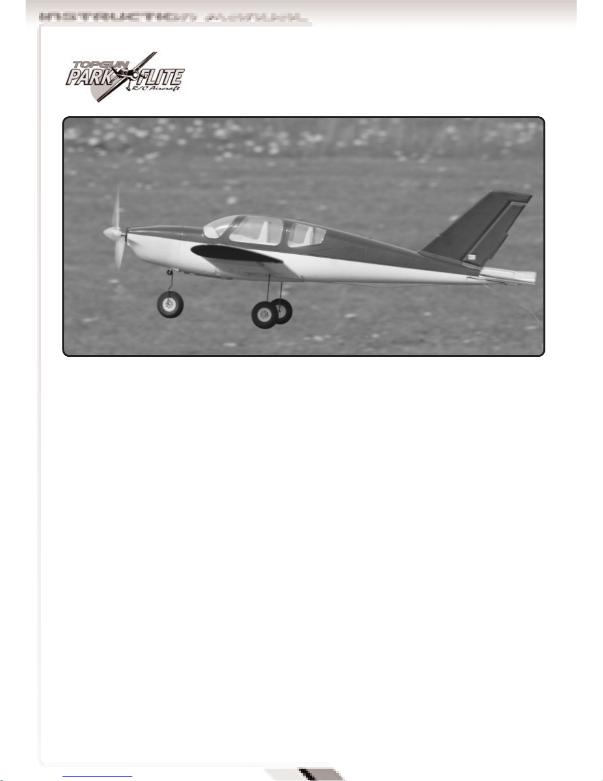
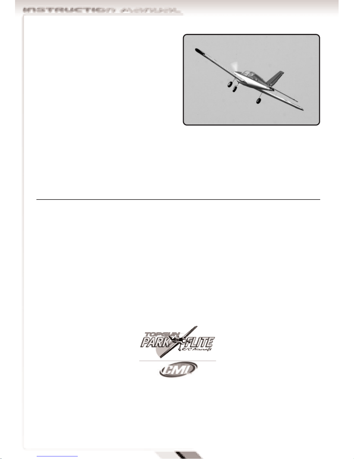
Top Gun Park Flite are proud to present this high
performance sport scale model of the Socata
Trinidad TB-20. We feel that this model emulates the
style, performance and character of its full size
counterpart.
Supplied as a Ready to Fly package with transmitter,
LiPo flight battery and charger, this model has been
designed with the utmost care and attention to detail
to produce a light weight, strong, and realistic looking
model aeroplane with excellent flying characteristics.
This model is a high performance miniature aircraft
that allows novice to intermediate model pilots to
perform both scale and aerobatic manoeuvers. The
light weight and large wing area allow the model to
fly extremely slowly, in a stable manner while still
maintaining full control.
These instructions assume a reasonable level of
competence for both building and flying and we
recommend that the model is flown at a recognised
club with frequency control measures and suitable
third party insurance.
The owner – pilot of this model should take note of
regulations, and local bylaws before flying this
aircraft.
Please take time to read through these instructions
before commencing assembly. We list operations in
order of works to reduce the risk of damage during
assembly.
Please read through the warnings before use.
A 7.4V 1800 mAh lithium polymer (LiPo) battery and
charger is included as part of this package and
these cells must be operated with care to prevent
the risk of fire.
LiPo Batteries are soft cased and can be easily
damaged by sharp items, puncturing of the soft
casing can cause fires and we recommend that they
are stored and handled carefully.
Use only a LiPo rated charger, set to a maximum of 2
cells (7.4v) and no more than 1 amp charge current.
Remove battery from the aircraft and charge on a
non flammable, non conductive surface
Due to continual and ongoing product development
the parts shown in the manual may differ from those
supplied.
Congratulations on purchasing the TB–20 RTF
3
Wing with ailerons connected to factory installed
servos
Fuselage with motor, Electronic Speed Control
(ESC) receiver, two quantity servo, and pushrods.
Fin and rudder assembly
Horizontal stabiliser (Tail plane) with elevator
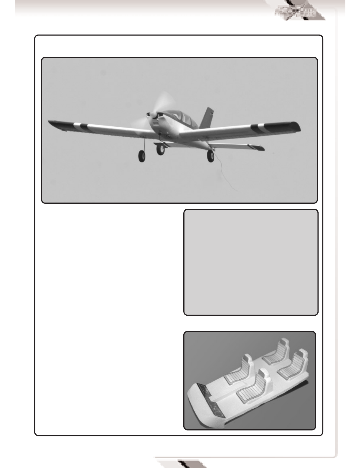
Main undercarriage assembly mounting plate and
wheels
4 function fully proportional 35Mhz transmitter
Control horns and back plates for elevator and
rudder
Tube of adhesive
LiPo Battery 2 cell 7.4V 1800 mAh (12c)
LiPo charger and 12v power lead
Propellor –8” diameter x 6” pitch with spinner
Self adhesive decal sheet.
KIT CONTENTS AND DESCRIPTION
SPECIFICATIONS
Wing span 1040 mm (41”)
Length 795 mm (31.25”)
Wing Area 16.7 Dm? (257 sq inches)
Weight 585 g (20 Ounces)
Radio 4 function 35Mhz PPM
3 Qty micro servos
18 Amp brushless ESC
Motor Brushless out runner
]8” x 6” Propellor
7.4 v 1800mAh LiPo battery

4
SECTION 1: KIT CONTENTS AND
DESCRIPTION CONTINUED
FUSELAGE ASSEMBLY.
Supplied complete and ready for use with brushless
motor installed and connected to Electronic Speed
Control (ESC),
35mhz receiver pre-wired to ESC, rudder, and
elevator servos.
Elevator, rudder and steering push rods installed
Nose wheel and screw on retaining cap.
WING ASSEMBLY.
Supplied as two halves.
Each half includes fitted and hinged aileron,
aileron torque rods with control horn and main
undercarriage fixing plates.
Hardwood wing joiner.
WING FIXING HARDWARE
Leading edge fixing plate

5
Wing bolts 2 off
Aileron servo with loose servo arm and fixing
screw.
Two aileron pushrods with plastic snap link clevis
connectors.
Vertical and Horizontal Stabilisers
Vertical Stabiliser (Fin and rudder) with moulded in
hinges and fitted control horn.
Horizontal Stabiliser (tail plane and elevator) with
moulded in hinges and fitted control horn.
Main Undercarriage assemblies.
Two sets of lightweight wheels fixed onto wire
torque rod undercarriage.
Four clamp plates and 8 fixing screws for securing
to wing plates.
Steerable nose gear is pre fitted to fuselage.
BATTERY AND CHARGER
7.4V (2 cell) 1800mAh (C) LiPo Battery rated at 12C
max discharge.
12v DC input 0.8 Amp output balancing type fast
charger
12v crocodile clip connecting lead
8” diameter x 6” pitch moulded propellor.

6
Ensure text is on front face when mounting.
Moulded spinner
Adhesive
5ml tube of foam safe adhesive.
Note pierce end of tube with pin in screw on lid.
SECTION 2: BATTERY AND CHARGER
BATTERY AND CHARGER
The kit includes a high performance 7.4V (3 cell)
1800mAh LiPo Battery rated at 12C (21 amp) max
discharge.
This must be charged using the dedicated 12v DC
input 0.8 Amp output fast charger and connecting
lead.
Connect the crocodile lead connectors to a 12V DC
power source (a 12V car battery is ideal), ensuring
that correct polarity is observed. Red is positive (+)
and Black is Negative (-).
Connect the lead into the battery charger. And the
Red LED will illuminate.
Push the white balance
plug of the battery into
the matching charger
output socket to
commence charging.
The green LED
illuminates to confirm
charging and switches off when the charge is
complete
A full charge will take between 2 and 3 hours.
WARNING:
A lithium polymer (LiPo) battery and charger is
included as part of this package, these cells
must be operated with care to prevent the risk of
fire.
LiPo Batteries are soft cased and can be easily
damaged by sharp items, puncturing of the soft
casing can cause fires and we recommend that
they are stored and handled carefully.
Remove battery from the aircraft and charge on a
non flammable, non conductive surface

7
TRANSMITTER
The RIR 4EXA is a fully proportional 4 function
35Mhz transmitter
The transmitter is supplied in a Mode 2
configuration. Mode 2 is also known as Throttle
Left.
The left stick controls Throttle and rudder
movement.
The right stick controls aileron and elevator
movement.
Battery state is indicated by a bank of coloured
LED’s. With green for full and red for empty.
As soon as the indicator changes to amber the
model should be landed to allow battery
replacement.
A red LED indicates dangerously low voltage.
The model should be landed immediately to replace
batteries before all control is lost.
Frequency control is by removable crystal.
The transmitter frequency is identified on the
crystal holder located on the front of the
transmitter.
8 off AA size dry cells or high capacity Nimh
batteries must be inserted before operation.
Remove the rear cover and install batteries into the
battery tray as directed by the moulded in polarity
(+ & -) markings.
A small panel of five small slide switches is set on
the front panel of the transmitter.
Switches 1 to 4 are electronic servo reversing
switches and should be adjusted to give the correct
control surface deflections relative to stick
movements.
The mix switch activates a ch1-ch2 mix to give
elevon (2 servos both functioning as ailerons and
elevators) for delta winged aircraft
For the TB20 the mix switch must be in the ‘A-Nor’
position.
SECTION 3: ASSEMBLY
Locate the wing halves and wooden dihedral brace -
wing joiner.
Test fit the joiner in the slot formed in the wing and
dry fit the wings together.
8
Apply adhesive into the slot formed in one of the
wing halves and slide the wooden dihedral brace -
wing joiner firmly in position.
Ensure joiner is flush with top surface of wing. Wipe
off any excess adhesive and allow to dry.
Apply adhesive to the wing root and dihedral brace
slot in the remaining wing panel.
Slide the wooden dihedral brace - wing joiner in
position while butting the panels together.
Ensure that the wing halves are correctly aligned
with no visible gap and use tape or clips to hold in
place.
Wipe off any excess and adhesive allow to dry.
Locate the leading edge dowel plate and test fit in
the recess at the front of the wing.
When happy with location apply adhesive and press
firmly in place.
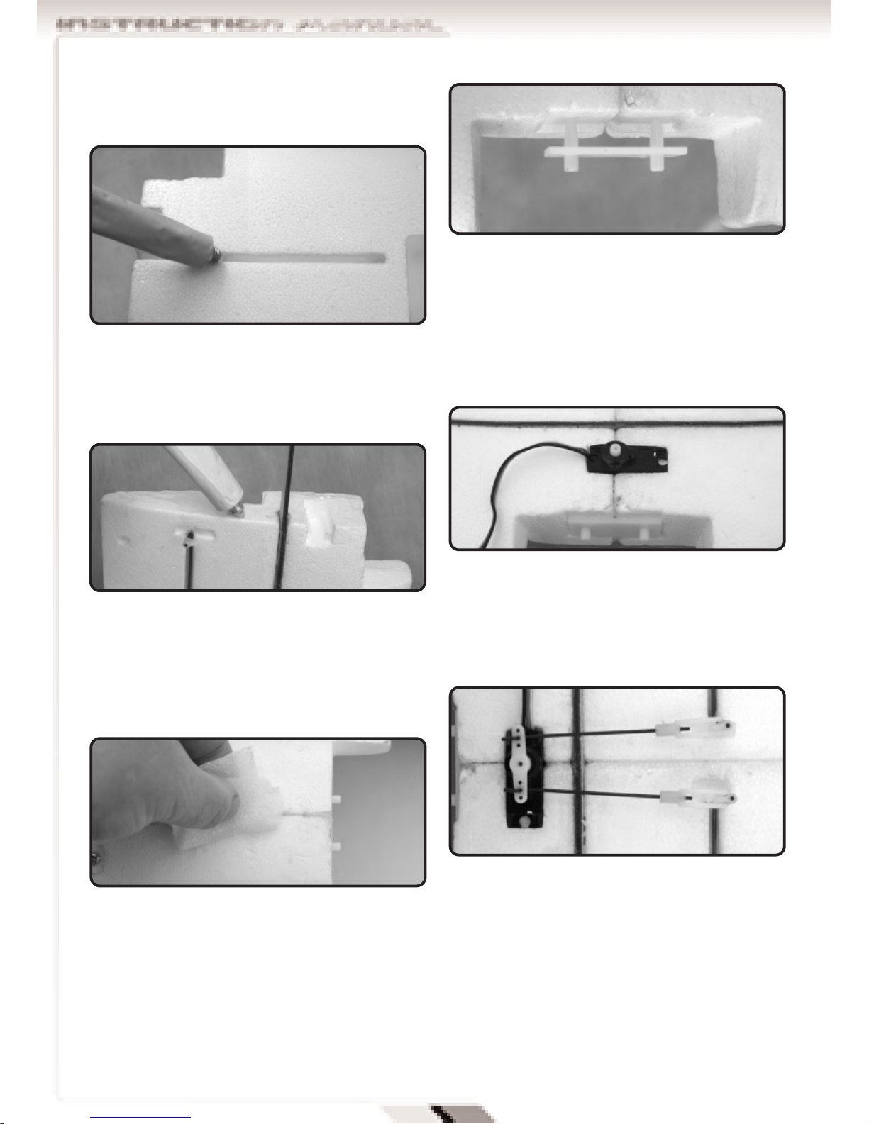
Locate the aileron servo with its pushrods and
connectors.
Apply a drop of adhesive to each side of the servo
and push into recess formed in wings.
The servo shaft should be central in the wing with
the lead exiting as shown
Connect the pushrods to the aileron control horns.
Push the servo arm onto the servo output shaft but
do not screw in place at this time.
Locate the main undercarriage assemblies, saddle
plates and fixing screws.
Insert undercarriage into mounting plate and fix in
place with saddles and four self tapping screws.
Locate the fuselage, horizontal stabiliser and two
fixing screws.
Position over the tail plane seat and tighten screws
securely.

9
Locate the fin and rudder assembly and test fit in
the fin slot.
Apply adhesive into the fin slot and insert the fin.
Check that the fin is vertical and square to the
fuselage and tail plane and adjust if necessary.
Use a damp cloth to wipe off excess adhesive and
allow to dry
Slide the nose wheel in place and screw the
retaining cap onto the wire to secure.
Apply the self adhesive decals to the top surface of
the wing as shown.
The rear of the decal lines up with the trailing edge
and aileron cut out.
Locate the wing assembly and position it near the
wing seating area .
Take the plug on the aileron servo lead and push
plug into channel no 1 of the receiver.
Switch on the transmitter and centre the servo
trims.
Temporarily connect the battery and ESC leads
together and check that aileron servo arm is
central. Adjust if necessary and secure with screw.
Disconnect battery.

10
Push the wing firmly down onto its seat until wing
leading edge pegs locate into mounting plate.
Ensure that aileron wire is inside fuselage
Fit the wing fixing screws and tighten until The
wing is firmly seated.
Fix propellor to prop shaft using the M3 aluminium
spinner nut.
Note that washers are fitted to both sides of the
propellor.
The text on the propellor faces forward.
Push the spinner firmly in place.
Construction is now complete and the following
steps can be considered as part of the daily
assembly and rigging of the model.
SECTION 4: FINAL SET UP
Open the hinged battery bay door by turning the
catches.
Insert into the battery and ensure that battery and
ESC leads project out of the aperture.
Ensure that transmitter is switched on.
Connect the battery and ESC leads together and
close the battery cover using the catches to lock it
in place.
Uncoil the receiver aerial and fully extend to hang
off the rear of the aircraft.
Check that all controls operate in the correct
manner and that surfaces for aileron, elevator and
rudder are level.
Adjust surfaces if required by unclipping the
pushrod clevis connectors and winding in or out to
suit.
WARNING:
With the battery connected and the model
switched on the motor is now live. The Electronic
speed controller (ESC) will go through its start up
procedure and will emit a series of beeps while it
configures throttle positions. The motor could
start unexpectedly and we recommend that the
model is restrained and that the operator keeps
clear of the propellor during handling.
11
To adjust the ailerons and nose wheel steering it is
necessary to remove the wing.
loosen the clamp connector before adjusting the
pushrod location.
With the trims and wheel central re-tighten the
clamp connector.
Move transmitter sticks to ensure free movement of
the control surfaces.
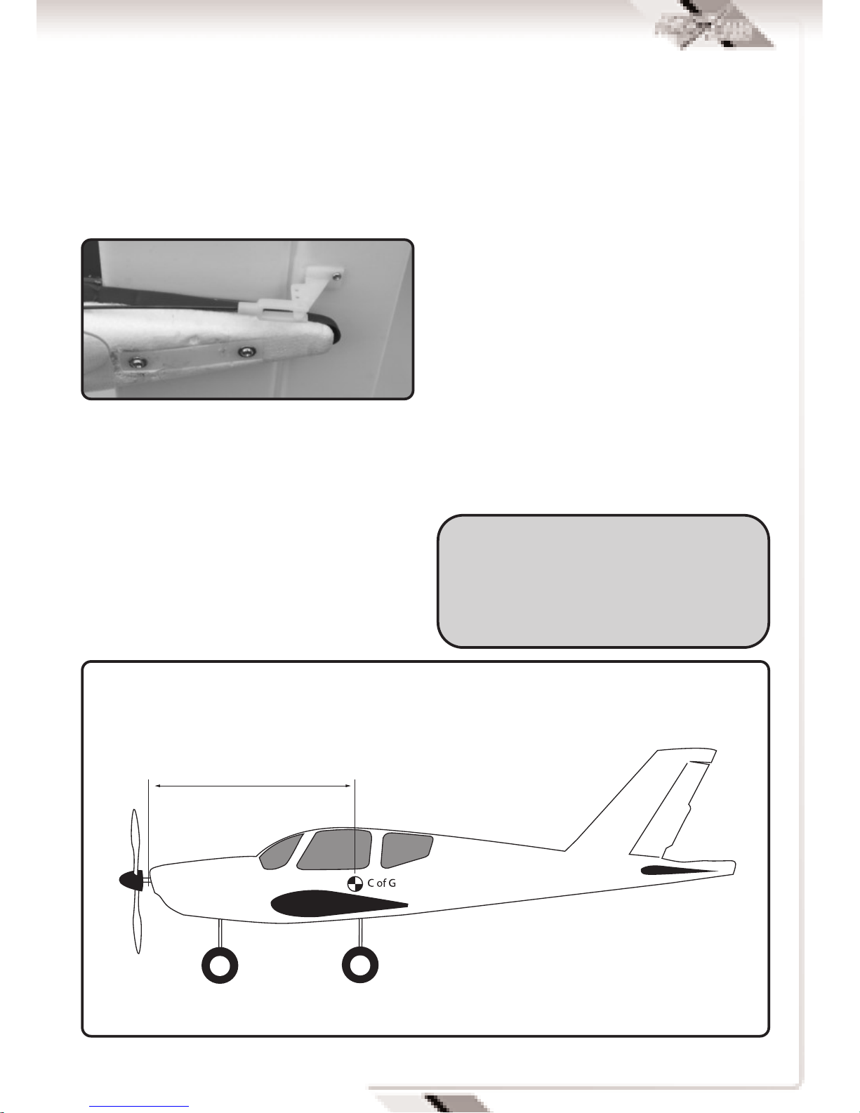
CHECK THE BALANCE.
The model should sit level or slightly nose down
when supported upside down from a point 50-54
mm from the wing leading edge. Add stick on lead
weights if necessary in order to achieve the correct
balance point.
DO NOT ATTEMPT TO FLY WITH A REARWARD
BALANCE POINT.
SECTION 5: FIRST FLIGHT
BEFORE THE TEST FLIGHT
On completion of the model take time to test rig the
model in the workshop several times.
Connect radio gear and double check that all
surfaces operate in the correct manner without
stalled servos.
Check for adequate range with and without motor
running.
If everything is okay, take it to the flying field and
rig it up again.
Always follow the frequency control procedures of
your local flying site and ensure that you have
adequate third party insurance cover.
Repeat the full pre flight inspection before flying.
WARNING:
Do not advance the throttle unless the model is
restrained. With the powerful motor-propellor
combination, the model will accelerate across a
smooth surface very quickly.
230mm
BALANCE POINT
12
FLYING
The TB20 is easily capable of 10 to 15 minute flight
times and can R.O.G (Rise Off Ground) from smooth
closely cut grass runways. It is aerobatic and able
to perform loops, rolls, and stall turns.
Due to its light weight it should not be flown in wind
greater than 10mph.
The use of rudder co-ordinated with aileron input
will produce smooth and scale like turns.
Control throws set during assembly will produce a
model capable of flying smooth scale like
performance and medium to high speed aerobatic
manoeuvers.
The control surface movements can be increased by
moving the clevis connectors nearer to the control
surfaces.
To reduce movements move the pushrod
connections nearer to the servo on the output arms
and further out along the control surfaces horns.
ENJOY YOURSELF BUT ALWAYS FLY SAFE!
TGP0155R TB20 EP Red Upper Fuselage
TGP0155B TB20 EP Blue Upper Fuselage
TGP0156 TB20 EP Lower Fuselage
TGP0157R TB20 EP Red Main Wing
TGP0157B TB20 EP Blue Main Wing
TGP0158R TB20 EP Red Wing Tips
TGP0158B TB20 EP Blue Wing Tips
TGP0159R TB20 EP Red Tail Wing Sets with
Vertical Tai /Horizontal Tail
TGP0159B TB20 EP Blue Tail Wing Sets with
Vertical Tai /Horizontal Tail
TGP0160R TB20 EP Red Front Nose Cowl
TGP0160B TB20 EP Blue Front Nose Cowl
TGP0161 TB20 EP Propeller 8x6
TGP0162 TB20 EP Spinner
TGP0163 TB20 EP Plastic Parts
TGP0164 TB20 EP Rear Landing Gear
TGP0165 TB20 EP Front Landing Gear
TGP0166 TB20 EP Aluminium Motor Frame
TGP0525 Top Gun Park-Flite 1800mAh 12c 7.4v
Lipo Battery (TB20)
TGP0534 Top Gun Park-Flite Bell 80w Outrunner
Brushless (TB20)
TGE0001 Etronix 8.4G Micro Servo
TGE0051 Etronix 25A Brushless Speed Control
DISTRIBUTORS OF QUALITY MODEL & HOBBY PRODUCTS
Saxon House, Saxon Business Park, Hanbury Road, Bromsgrove, Worcestershire. B60 4AD. England
Tel: +44 (0) 1527 575349 Fax: + 44 (0) 1527 570536
E-mail: [email protected]
Web site: www.cmldistribution.co.uk
TOP GUN PARKFLITE TB–20 SPARE PARTS LIST
Table of contents
Other Torgun Toy manuals

Popular Toy manuals by other brands

Mattel
Mattel N9795 instruction sheet

LEGO
LEGO Duplo Disney Junior Sofia the First 10822 Assembly manual

Faller
Faller 130232 manual

THE WORLD MODELS
THE WORLD MODELS Spot-On 50 instruction manual

Trends Audio
Trends Audio Peppa Pig Peppa’s Smart Tablet PP04 instruction manual

Fisher-Price
Fisher-Price 71922 instructions


Thames & Kosmos
Thames & Kosmos ANiMALS operating manual

Peg-Perego
Peg-Perego IMGIRE00 Series Instructions for use

Agora Models
Agora Models OPTIMUS PRIME Pack 02 Build instructions

Accucraft trains
Accucraft trains D&RGW C-25 2-8-0 instruction manual

goliath
goliath Star Wars Domino Express R2-D2 Dealer instructions

Mega Bloks
Mega Bloks Collector Series instructions