Tormach Collet Closer 5C Technical manual
Page 1
Tormach Inc.
1071 Uniek Drive, Waunakee, WI 53597
Phone: 608.849.8381 / Fax: 209.885.4534
©Tormach® 2014. All rights reserved.
Specicaons subject to change without noce.
TD10249_Collet_Closer_Install_0117A
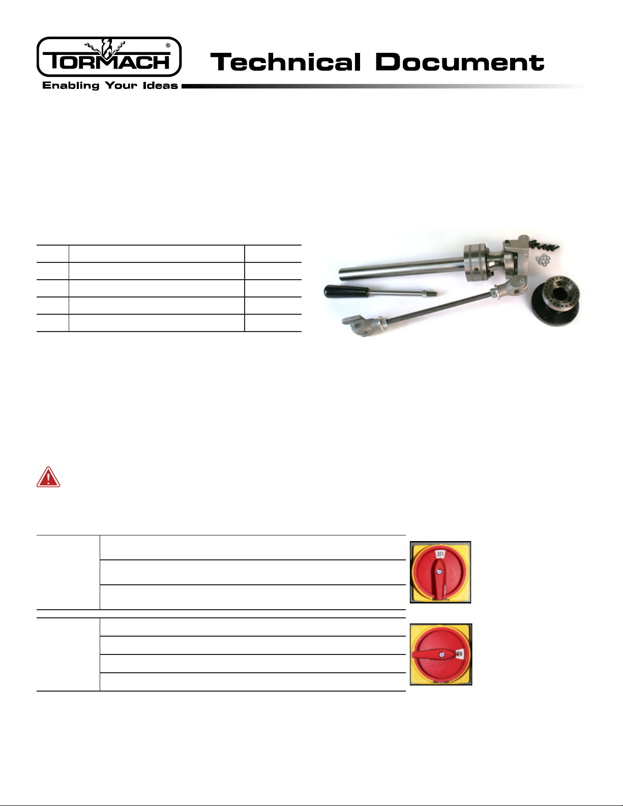
Collet Closer Installation
Product Idencaon: 5C Collet Closer (PN 33283)
Purpose: This document details the installaon and use of the collet closer on a 15L Slant-PRO lathe.
Qty.5C Collet Closer PN
1 Collet Closer —
1Index Ring/Adapter Assembly —
1 Collet Handle —
6 M6 Socket Head Cap Screw —
6M6 Lock Washer —
NOTE: If any of these items are missing, contact Tormach
Customer Service at (608) 849-8381 for a replacement.
Required Tools:
• .0005” Magnetic Dial Indicator (PN 31947) • Dead-blow hammer
• Bandsaw or hacksaw • Machinist’s stone or similar
WARNING! Electrical Shock Hazard: Be sure to power o machine before making any electrical
modicaons. Failure to do so may result in serious injury or death.
Power Off/On Procedure
Power Off
1. Push in red E-stop button
2. Click Exit on screen; when prompted click OK to power off
3.Turn Main Disconnect Off (see image at right)
Power On
1.Turn Main Disconnect On (see image at right)
2.After software loads, t
urn red E-stop clockwise to release
3. Press green Start button
4. Click Reset on screen

Page 2
Tormach Inc.
1071 Uniek Drive, Waunakee, WI 53597
Phone: 608.849.8381 / Fax: 209.885.4534
©Tormach® 2014. All rights reserved.
Specicaons subject to change without noce.
TD10249_Collet_Closer_Install_0117A
Installation
1. Remove four Phillips-head screws securing
panel to belt guard (see Figure 1); set aside for
future use.
2. Unscrew Power Connector from Rotary
Encoder (see Figure 2).
3. Loosen ve Phillips-head screws securing belt
guard cover to lathe; remove cover and set all
aside (see Figure 3).
Figure 1 Figure 2
Rotary Encoder
Power Connector
Figure 3
Page 3
Tormach Inc.
1071 Uniek Drive, Waunakee, WI 53597
Phone: 608.849.8381 / Fax: 209.885.4534
©Tormach® 2014. All rights reserved.
Specicaons subject to change without noce.
TD10249_Collet_Closer_Install_0117A
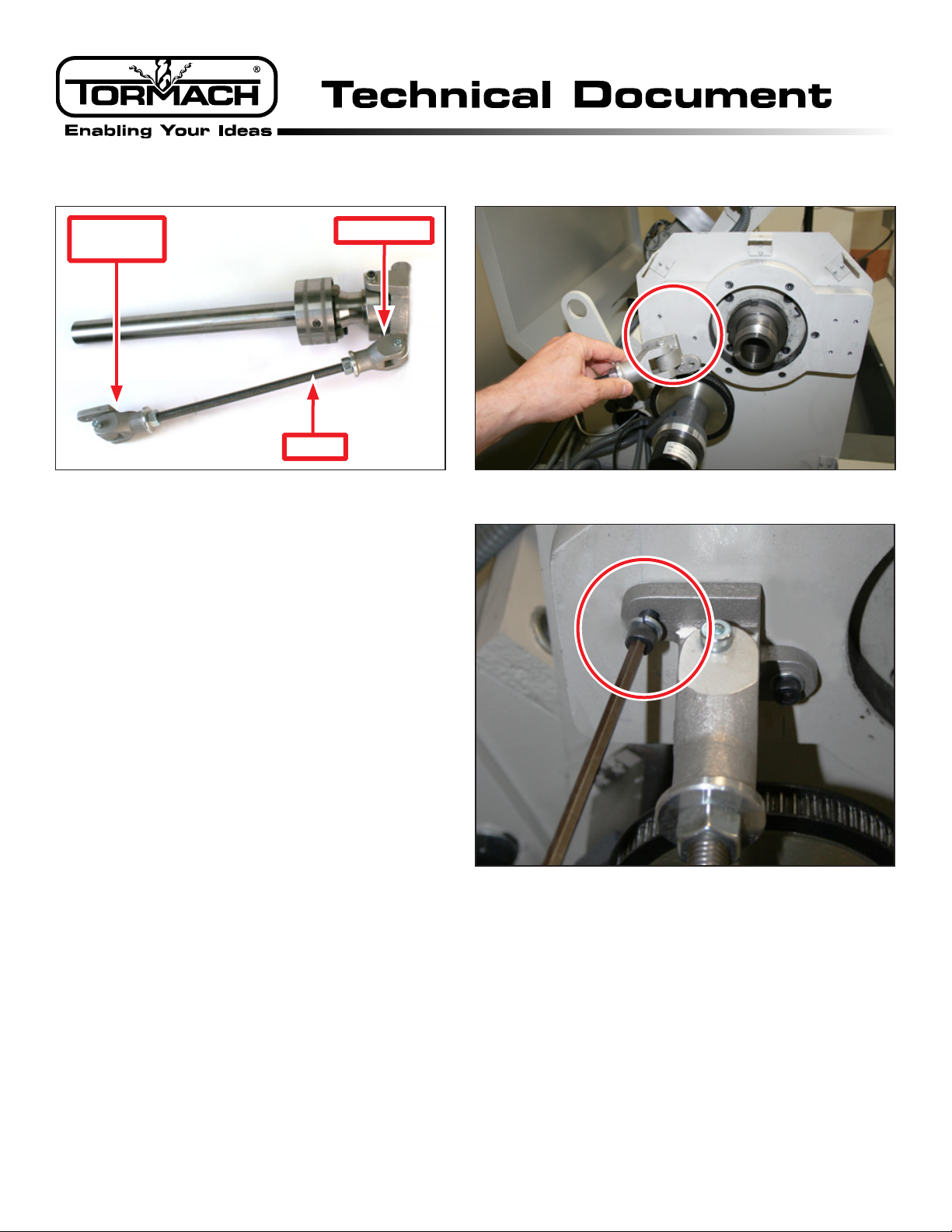
4. Unscrew Rod from Connector (see Figure 4) on
Collet Closer.
5. Locate two pilot holes on lathe to aach
Connector Bracket (see Figure 4 and Figure 5).
6. Using two M6 Socket Head Cap Screws and two
M6 Lock Washers, aach Connector Bracket to
lathe (see Figure 6).
Figure 4
Connector
Bracket
Connector
Rod
Figure 5
Figure 6

Page 4
Tormach Inc.
1071 Uniek Drive, Waunakee, WI 53597
Phone: 608.849.8381 / Fax: 209.885.4534
©Tormach® 2014. All rights reserved.
Specicaons subject to change without noce.
TD10249_Collet_Closer_Install_0117A
7. Using machinist’s stone or similar, lightly
stone the back of the Index Ring/Adapter
assembly and the face of the spindle pulley
(see Figure 7) to remove burrs. Presence of
burrs may cause runout.
8. Using four M6 Socket Head Cap Screws and four
M6 Lock Washers, aach Index Ring/Adapter
Assembly to spindle pulley (see Figure 8).
9. Aach .0005” magnec dial indicator to lathe
and posion indicator p against index ring
(see Figure 9).
Figure 8
Index Ring/
Adapter
Assembly
Figure 9
Figure 7
Deburr

Page 5
Tormach Inc.
1071 Uniek Drive, Waunakee, WI 53597
Phone: 608.849.8381 / Fax: 209.885.4534
©Tormach® 2014. All rights reserved.
Specicaons subject to change without noce.
TD10249_Collet_Closer_Install_0117A
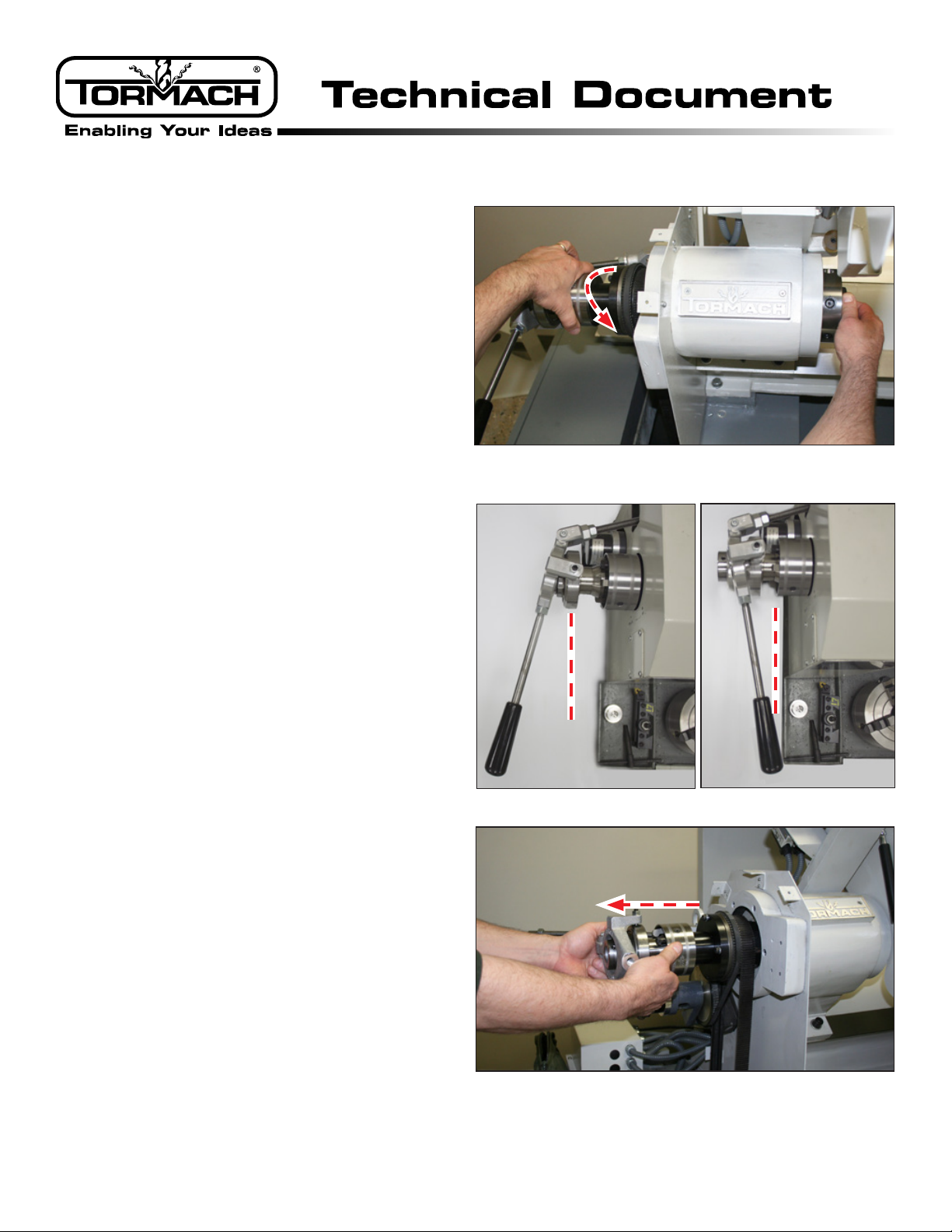
10. Slowly pull down on spindle belt to rotate index
ring (see Figure 10); complete one full cycle
and make note of reading on dial indicator.
Alignment should hold a total indicated runout
of 0.001” or beer.
11. If reading on indicator moves more than
0.001”, carefully loosen three socket head cap
screws on Index Ring and tap with a dead-blow
hammer to bring center in line with lathe’s
spindle bore (see Figure 11).
12. Repeat Step 10 and Step 11 unl alignment is
achieved.
13. Carefully ghten three socket head cap screws
on Index Ring.
14. Temporarily insert Collet Closer into lathe’s
spindle bore (see Figure 12).
Figure 11
Index
Ring
Figure 12
Figure 10
Page 6
Tormach Inc.
1071 Uniek Drive, Waunakee, WI 53597
Phone: 608.849.8381 / Fax: 209.885.4534
©Tormach® 2014. All rights reserved.
Specicaons subject to change without noce.
TD10249_Collet_Closer_Install_0117A
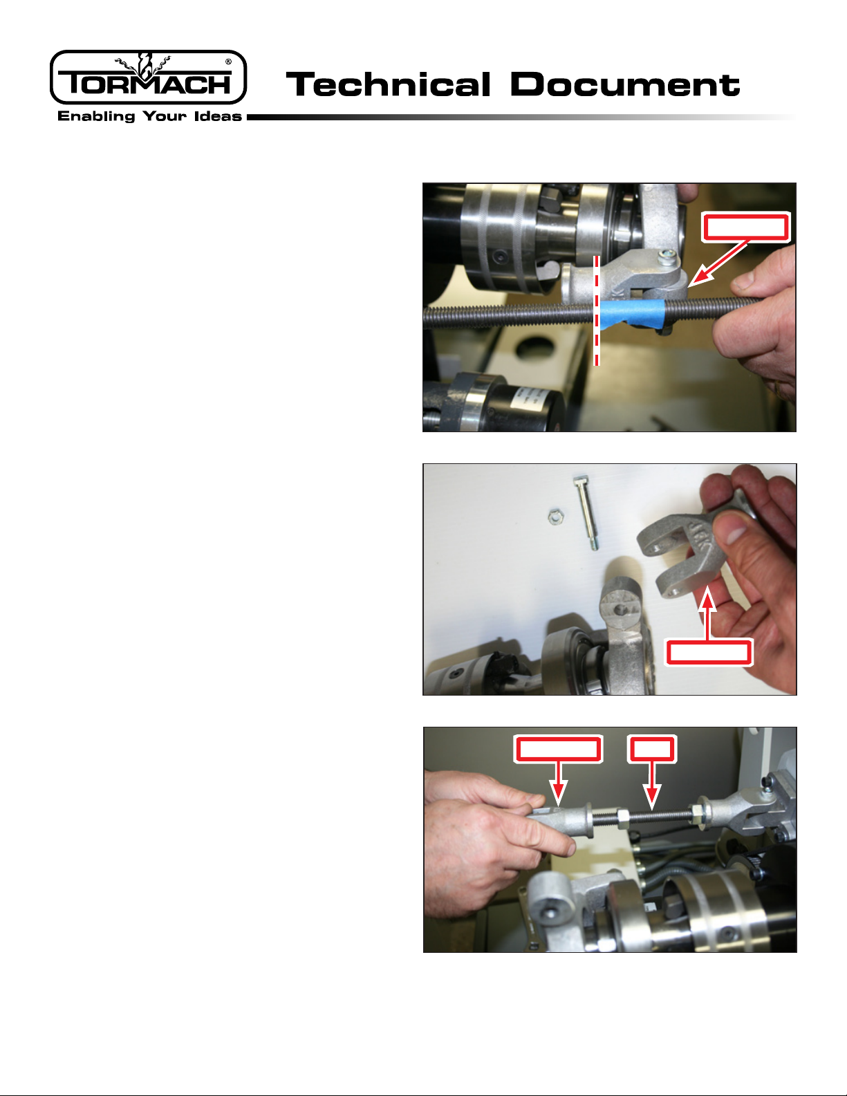
15. Posion rod next to Connector on Collet Closer;
esmate length of rod necessary for full range
of moon and mark with tape (see Figure 13).
NOTE: Required rod length varies; adjustments
may be necessary aer Collet Closer installaon is
complete.
16. Using a bandsaw or hacksaw, cut rod as
determined in Step 15.
17. Lightly stone newly-cut end of rod.
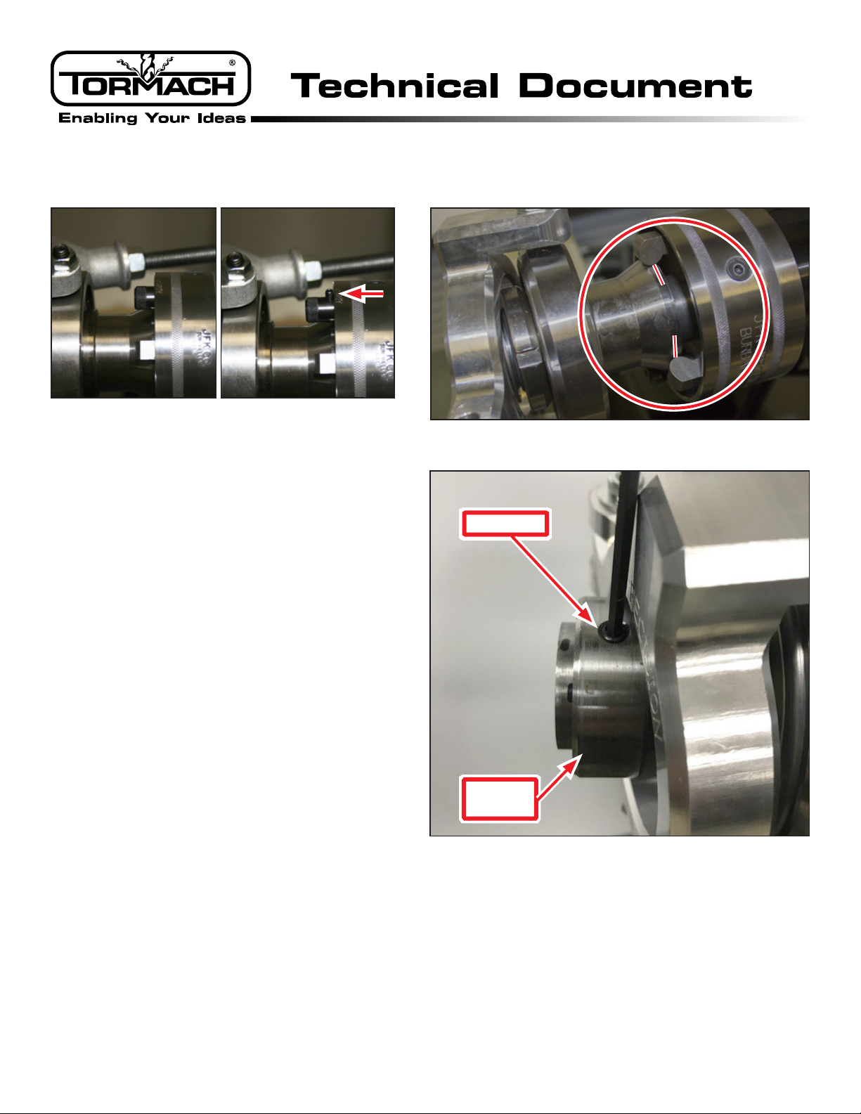
18. Remove Connector from Collet Closer by
removing nut and bolt (see Figure 14).
19. Screw Connector onto newly-cut end of Rod;
(see Figure 15) using nut, ghten securely.
Figure 13
Connector
Figure 14
Connector
Figure 15
Connector Rod
Page 7
Tormach Inc.
1071 Uniek Drive, Waunakee, WI 53597
Phone: 608.849.8381 / Fax: 209.885.4534
©Tormach® 2014. All rights reserved.
Specicaons subject to change without noce.
TD10249_Collet_Closer_Install_0117A
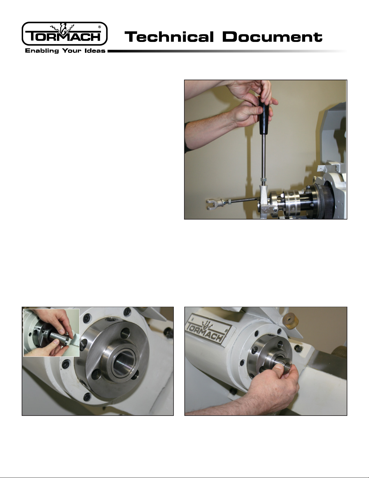
20. Screw Collet Handle into Collet Closer; ghten
securely (see Figure 16).
21. Re-aach Connector to Collet Closer with nut
and bolt set aside in Step 18; ghten securely.
NOTE: Connector should be able to move freely.
22. Ensure 5C insert (included with lathe) is inserted in spindle (see Figure 17 and inset).
23. Insert 5C collet (not included) into adapter and rotate to engage the collar’s internal pin with the groove
on the collet (see Figure 18).
Figure 16
Figure 17 Figure 18
Page 8
Tormach Inc.
1071 Uniek Drive, Waunakee, WI 53597
Phone: 608.849.8381 / Fax: 209.885.4534
©Tormach® 2014. All rights reserved.
Specicaons subject to change without noce.
TD10249_Collet_Closer_Install_0117A
24. Hold the collet sll in the spindle with one
hand; using the other hand, turn the Collet
Closer’s collar clockwise to thread it on to the
collet (see Figure 19).
25. Insert a piece of material into the collet and
turn the Collet Closer’s collar clockwise unl
desired tension is achieved on the workpiece.
IMPORTANT! Avoid excess tension on collet.
26. Move the collet handle back and forth between
the locked posion (away from the headstock)
and the released posion (toward the
headstock). Ensure handle is past centerline in
either posion (see Figure 20).
IMPORTANT! If collet handle is not past center
in the locked posion (see Figure 20), adjust
rod length unl proper alignment is achieved.
27. Temporarily remove Collet Closer from lathe
spindle assembly (see Figure 21).
28. Using ve Phillips-head screws, reaach Belt
Guard Cover to lathe.
29. Re-insert Collet Closer into lathe spindle
assembly.
30. Re-install power connector to rotary encoder.
Figure 20
Locked Released
Figure 21
Figure 19

Page 9
Tormach Inc.
1071 Uniek Drive, Waunakee, WI 53597
Phone: 608.849.8381 / Fax: 209.885.4534
©Tormach® 2014. All rights reserved.
Specicaons subject to change without noce.
TD10249_Collet_Closer_Install_0117A
31. Proceed to Operaon secon to idenfy any
adjustments required to operate the collet
closer. You have now completed the installaon
(see Figure 22).
Operation
1. With a piece of material inserted in the collet,
ensure the Collet Closer is in the released
posion (see Figure 20), with the collet handle
toward the headstock.
2. Idenfy Index Pin on Collet Closer’s index plate
(see Figure 23).
Figure 23
Figure 22
Page 10
Tormach Inc.
1071 Uniek Drive, Waunakee, WI 53597
Phone: 608.849.8381 / Fax: 209.885.4534
©Tormach® 2014. All rights reserved.
Specicaons subject to change without noce.
TD10249_Collet_Closer_Install_0117A
3. Ensure the index pin is in the Pin Out posion
(see Figure 24).
NOTE: When the pin is in, the collet closer is in run
mode. When the pin is out, the collet closer is in
adjust mode.
4. Move the collet handle to the locked posion
(away from the headstock); ensure cams are
centered on the hub as shown in Figure 25.
If the cams are not centered on the hub:
• Rotate Stop Collar to access Set Screw on
Collet Closer (Figure 26); loosen set screw.
• Slide unit forward or backward unl cams
rest in center of hub as shown in Figure 25.
• When adjustment is complete, re-ghten
set screw on Collet Closer’s hub.
5. Move the Index Pin to the Pin In posion (see
Figure 24) by twisng to release and allowing
it to enter the closest hole in the index plate.
NOTE: If necessary, turn the collar slightly to allow the index pin to seat completely.
6. With the Index Pin in the Pin In posion, the collet closer is in run mode. You have now adjusted the collet
closer for operaon.
Figure 25
Figure 26
Set Screw
Stop
Collar
Figure 24
Pin In Pin Out
Page 11
Tormach Inc.
1071 Uniek Drive, Waunakee, WI 53597
Phone: 608.849.8381 / Fax: 209.885.4534
©Tormach® 2014. All rights reserved.
Specicaons subject to change without noce.
TD10249_Collet_Closer_Install_0117A
Troubleshooting
Problem Possible Cause Discussion
Handle wobbles
Runout on Index Ring/Adapter Ensure both sides of Index Ring/Adapter assembly are
free of debris (see Figure 7).
Connector and/or connector bracket
is too loose or too tight
Adjust bolts on connector and connector bracket as
necessary (see Figure 14).
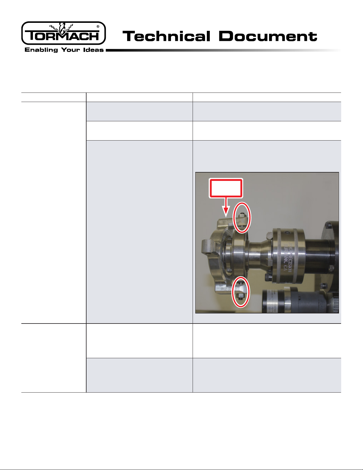
Handle casting is not centered
Loosen top and bottom height screw locknuts (see
Figure 27) on Handle Casting and adjust set screws
until it is centered.
Handle
Casting
Figure 27
Handle moves itself to
the released position
or
Index pin does not
engage in index ring
Cams are not centered on the hub
Loosen Set Screw on Stop Collar (see Figure 26) and
slide unit until cams rest in the center of the hub (see
Figure 25). Re-tighten Set Screw.
Threaded rod is too long
Ensure handle is past centerline when in the locked
position (see Figure 20). If not, make adjustments to
threaded rod length – either cut the rod or tighten it
further into connector and/or connector bracket.
This manual suits for next models
1
Table of contents
Other Tormach Lathe manuals


