Tormach 8L User manual

Original Instructions
OPERATOR'S MANUAL Version 0321B

Copyright
Notice
Information is subject to change without notice by Tormach, Inc. For the most recent version of this document,
see tormach.com/support.
You're welcome to make copies of this document for evaluating, learning about, and/or using the machine.
You may not charge for any copies you make beyond the cost of printing.
Unless otherwise noted, companies, names, and various data used in examples are fictitious.
To the Reader
We're dedicated to continually improving our documentation and products, and welcome any clarifications,
corrections, or suggestions.
Credits
Tormach®, 8L®, and PathPilot® are trademarks or registered trademarks of Tormach, Inc. Our milling machines
and accessories are covered by one or more of the following U.S. Patents: 7,386,362; D606,568; D612,406;
D621,859; and other patent(s) pending.
Other product or company names may be the trademarks of their respective owners.
Copyright © Tormach, Inc. 2021
Page 2

©Tormach® 2021
Specifications subject to change without notice.
Page 3 UM10753: 8L Operator's Manual (Version 0321B)
For the most recent version, see tormach.com/support
ABOUT THIS DOCUMENT
SAVE THESE INSTRUCTIONS!
This document contains important safety warnings and
operating instructions for your machine. Before operating this
machine in any way, you and all other operators must read and
understand all instructions. If you don't, there's a risk of voided
warranty, property damage, serious injury, or death.
Keep these instructions with your machine so that they're
readily accessible.
PURPOSE AND SCOPE
This document is intended to provide sufficient information to
allow you to install, configure, and use your machine. It
assumes that you have appropriate experience and/or access
to training for any computer-aided design or manufacturing
software for use with the machine.
GETTING HELP
We provide no-cost technical support through multiple
channels. The quickest way to get the answers you need is
normally in this order:
1. Read this document.
2. Read related documents at tormach.com/support.
3. If you still need answers, gather the following
information so that we may help you as quickly as
possible:
lYour phone number, address, and company name (if
applicable).
lMachine model and serial number, which are located
next to the Main Disconnect switch.
lThe version of PathPilot that you’re running.
lAny accessories that you have for your machine.
lA clear and concise description of the issue.
lAny supporting media and information that you can
share with us. For example, you could:
oAnalyze what might have changed since the
machine last worked correctly.
oRecord a short video.
oTake a picture of a part.
oFor software, share log data .zip files, screen
captures, or program files.
For information, see "Share LogData .zip Files"
(below).
oFrom the PathPilot interface, on the Status tab,
record any available information.
oUse a digital multimeter for voltage readings.
4. Once you've gathered the information in Step 3, contact
us in the following ways:
a. Email: support@tormach.com
b. Phone: (608) 849-8381 (Monday through Friday, 8
a.m. to 5 p.m. U.S. Central Standard Time)
SHARE LOGDATA .ZIP FILES
The controller keeps log data on how the machine has been
working, which you can export as a .zip file. This information
helps us troubleshoot software situations much faster.
To share log data .zip files:
1. Put a USB drive into the PathPilot controller.
2. From the PathPilot controller, on the Status tab, select
Log Data.
PathPilot creates a file called logdata_[TODAY'S-
DATE].zip, and saves it on your USB drive.
3. Remove the USB drive from the controller. Email
support@tormach.com to contact Tormach Technical
Support for guidance on how to proceed.
ADDITIONAL INFORMATION
For additional technical information and support videos, see
tormach.com/support.
LIABILITY DISCLAIMER
We've made every effort to provide comprehensive and
accurate information, but no warranty or fitness is claimed or
implied. All information provided is on an as is basis. The
authors, publisher, and Tormach, Inc. ("we", "us", and so on)
shall not have any liability for, or responsibility to, any person
or entity for any reason for any loss or damage arising from
the information contained in this document.
This document provides guidance on safety precautions and
techniques, but because the specifics of any one workshop or
other local conditions can vary greatly, we accept no
responsibility for machine performance or any damage or
injury caused by its use. It's your responsibility to verify that
you fully understand the implications of what you're doing and
comply with any legislation and codes of practice applicable to
your city, state, or nation.


SAFETY 11
1.1 Intended Use 12
1.2 Machine Standards 12
1.2.1 American National Safety Institute (ANSI) 12
1.2.2 Occupational Safety and Health Administration (OSHA) 12
1.3 Safety Overview 12
1.3.1 Safety Messages 12
Personal Injury 12
Property Damage 13
1.3.2 Safety Decals 13
On the Electrical Cabinet Door 13
Next to the Main Disconnect 13
On the Rear of the Headstock 14
1.3.3 Information Decals 14
Serial Number Plate 14
1.4 Machine Safety 14
1.4.1 General Shop Safety 14
1.4.2 Operational Safety 15
General 15
Tooling 16
Workholding 16
1.4.3 Electrical Safety 16
ABOUT YOUR MACHINE 17
2.1 Specifications 18
SITE REQUIREMENTS 19
3.1 General Site and Space Requirements 20
3.1.1 Site Requirements 20
3.1.2 Space Requirements 20
3.2 Electrical and Power Requirements 20
3.2.1 Electrical Requirements 20
3.2.2 Power Requirements 20
3.2.3 Options for Non-Conforming Sites 21
INSTALLATION 23
4.1 Before You Begin 24
4.2 Installation Tools and Items 24
4.3 Move the Pallet 24
4.4 Assemble the Machine Stand 24
TABLE OF CONTENTS

©Tormach® 2021
Specifications subject to change without notice.
Page 6 UM10753: 8L Operator's Manual (Version 0321B)
For the most recent version, see tormach.com/support
4.5 Unpack the Machine Crate 25
4.6 Install Core Components 26
4.6.1 Lift and Move the Machine 26
Secure the Machine to the Stand 27
Secure the Machine to a Workbench 27
4.6.2 Install the Controller Arm 28
Install the PathPilot Operator Console 29
Install the Monitor 31
Install the PathPilot Controller 32
4.6.3 Verify the Installation 33
Power On the Machine 33
Power Off the Machine 35
Verify Limit Switch Function 35
Verify Axes Function 35
Verify Spindle Function 36
4.7 Install Accessory Components 36
4.7.1 Install the Quick Change Tool Post Kit 37
Required Tools 37
Install the Quick Change Tool Holder 37
Install the Tool into the Quick Change Tool Holder 37
To Use a Boring Bar 38
Align the Tool 38
4.7.2 Install the Machine Stand Coolant Kit (PN 50931) 39
Adjust the Coolant Pump Motor Strapping 40
4.8 Set Up the PathPilot Controller 40
4.8.1 Specify the Date and Time 40
4.8.2 Specify the Keyboard Language 40
4.8.3 Configure the Optional Touch Screen Kit 40
4.8.4 Update PathPilot 40
SYSTEM BASICS 41
5.1 System Reference 42
5.1.1 Spindle 42
About the Spindle 42
5.1.2 Axes 42
5.2 Basic Controls Reference 42
5.2.1 Machine Controls 42
5.2.2 PathPilot Interface 42
BASIC OPERATIONS 43
6.1 Start the Machine 44
TABLE OF CONTENTS

©Tormach® 2021
Specifications subject to change without notice.
Page 7 UM10753: 8L Operator's Manual (Version 0321B)
For the most recent version, see tormach.com/support
TABLE OF CONTENTS
6.2 Bring the Machine Out of Reset 44
6.2.1 About Reset Mode 44
6.3 Reference the Machine 44
6.3.1 About Referencing 44
6.4 Jog the Machine 44
6.4.1 About Jogging 45
About Continuous Velocity Jogging 45
About Step Jogging 45
6.4.2 Jog Controls Reference 45
Jogging in PathPilot 46
Jogging with the Keyboard 46
Jogging with the (Optional) JogShuttle 46
6.5 Change the Spindle Speed Range 46
6.6 Load Material into the Spindle 47
6.7 Load G-Code 48
6.7.1 Transfer Files to and From the Controller 48
6.8 Set Work Offsets 49
6.8.1 About Work Offsets 49
6.9 Set Tool Geometry Offsets 50
6.9.1 Touch Off the Tool Geometry Offsets 50
Touch X 50
Touch Z 51
6.9.2 About Tool Offsets 51
6.9.3 Import and Export the Tool Table 51
Import a .csv File 51
Export the Tool Table as a .csv File 51
6.10 Operate the Coolant Pump 52
6.10.1 About Coolant 52
MACHINE MAINTENANCE 53
7.1 Maintenance Safety 54
7.1.1 All Maintenance Procedures 54
7.1.2 Swarf Maintenance Procedures 54
7.1.3 Coolant Maintenance Procedures 54
7.2 Maintenance Schedules 54
7.2.1 Daily 54
7.2.2 Weekly 54
7.2.3 Monthly 54
7.2.4 Semi-Annually 54
7.2.5 Annually 54
7.3 Clean the Coolant System 54

©Tormach® 2021
Specifications subject to change without notice.
Page 8 UM10753: 8L Operator's Manual (Version 0321B)
For the most recent version, see tormach.com/support
7.3.1 About Cutting Fluid 55
7.3.2 Cutting Fluid Reference 55
7.4 Examine the Enclosure Windows 55
7.5 Examine the Spindle Belt 56
7.6 Lubricate the Machine 56
7.6.1 About the Manual Oiler 56
7.6.2 About the Automatic Oiler 56
7.6.3 Lubrication System Reference 56
7.7 Prevent Rust 56
TROUBLESHOOTING 57
7.8 Troubleshooting Safety 58
7.9 Getting Help 58
7.10 Required Tools 59
7.11 Frequently Found Problems 59
7.12 Power Distribution Subsystem 60
7.12.1 The Controller Won't Power On 60
7.12.2 The Coolant Pump Won't Run 61
7.13 Control Power Subsystem 62
7.13.1 The Machine Won't Power On 62
7.14 Axes Drive Subsystem 63
7.14.1 outAll Axes Won't Move When Commanded 64
7.14.2 One Axis Won't Move (or Only Moves in One Direction), and Other Axes Move 64
7.14.3 Axis Movement is Noisy 67
7.14.4 Can't Reference All Axes 68
7.14.5 Lost Motion on Axis Travel 70
7.15 Spindle Drive Subsystem 72
7.15.1 Spindle Turns in Reverse 72
7.15.2 The Spindle Won't Turn 73
Run and Direction Commands Reference 76
Spindle VFD Trip Reference 76
DIAGRAMS AND PARTS LISTS 79
7.16 Headstock Exploded View 80
7.17 Headstock Parts List 81
7.18 Stand Exploded View 83
7.19 Stand Parts List 84
7.20 Tailstock Exploded View 85
7.21 Tailstock Parts List 86
7.22 X-Axis Exploded View 87
7.23 X-Axis Parts List 88
TABLE OF CONTENTS

©Tormach® 2021
Specifications subject to change without notice.
Page 9 UM10753: 8L Operator's Manual (Version 0321B)
For the most recent version, see tormach.com/support
TABLE OF CONTENTS
7.24 Z-Axis Exploded View 90
7.25 Z-Axis Parts List 91
ELECTRICAL SCHEMATICS 93
7.26 115 Vac Power (Sheet 1) 94
7.27 24 Vdc Controls (Sheet 2) 95
7.28 Axis Drive Bus (Sheet 3) 96
7.29 Spindle Drive (Sheet 4) 97
7.30 Machine Control Board (Sheet 5) 98
7.31 Limit/Door Switches (Sheet 6) 99
7.32 Accessory Power (Sheet 7) 100
7.33 Grounds (Sheet 8) 101
7.34 Wiring Table (Sheet 9) 102
7.35 Electrical Cabinet Layout (Sheet 10) 103
7.36 Operator Console Schematic 104
7.37 Wiring Layout Diagrams 105
7.37.1 Power In 106
7.37.2 EMI Filter and Circuit Breaker 107
7.37.3 70 Vdc Power Supply and Stepper Driver Power 108
7.37.4 24 Vdc Safety Circuit Contactor 109
7.37.5 110 Vac Spindle Contactor 110
7.37.6 24 Vdc Power Supply 111
7.37.7 ECM Board Power 112
7.37.8 Coolant Pump and Accessory Power 113
7.37.9 Noise Suppressor 114
7.37.10 Spindle VFD 115
7.37.11 Spindle Encoder 116
7.37.12 Stepper Driver Signal and Stepper Motor 117
7.37.13 Limit/Door Switches 118

SAFETY
IN THIS SECTION, YOU'LL LEARN:
About the standards and safety precautions associated with this machine.
Before operating the machine in any way, you must read and understand this section.
Safe operation of the machine depends on its proper use and the precautions you take. Only trained personnel
— with a clear and thorough understanding of its operation and safety requirements — shall operate this
machine.
CONTENTS
1.1 Intended Use 12
1.2 Machine Standards 12
1.3 Safety Overview 12
1.4 Machine Safety 14

1.1 INTENDED USE
This machine is intended for general-purpose, computer
numerical control (CNC) machining in the following
applications:
lEducational environments
lHobby applications
lLight production
lPrototyping
lResearch and development
lSecondary operations
The intended use includes:
lAppropriate workholding, toolholding, tooling, coolant
systems, and machining parameters.
lMachining of conventional, non-abrasive materials such
as ferrous and non-ferrous metals below 60 HRC, woods,
and plastics.
The intended use does not include machining materials that:
lAre abrasive, carcinogenic, explosive, flammable,
radioactive, or toxic
lProduce aerosols or fine particulates when machined
The intended use does not include the following materials (not
a full list):
lBeryllium and its alloys
lCeramics
lFiberglass
lG10 fiberglass laminate
lGraphite
lMagnesium and its alloys
To safely operate products, you must obey all safety
precautions and warnings that are on the machines and in the
documentation.
1.2 MACHINE STANDARDS
When installed and operated as intended (see "Intended Use"
(above)), this machine complies with the following standards.
You must follow the requirements listed in the standards so
that the machine remains compliant.
1.2.1 American National Safety Institute (ANSI)
lANSI B11.TR3-2000 Risk Assessment and Risk
Reduction — A Guideline to Estimate, Evaluate, and
Reduce Risks Associated with Machine Tools
lANSI B11.5-1984 (R1994) Lathes
lANSIB11.22-2002 Safety Requirements for Turning
Centers and Automatic Numerically Controlled Turning
Machines
1.2.2 Occupational Safety and Health Administration
(OSHA)
lOSHA 1910.212 General Requirements for All
Machines
1.3 SAFETY OVERVIEW
Any machine tool is potentially dangerous. A CNC machine's
automation presents added risk not present in a manual
machine.
Before operating the machine in any way, you must read and
understand this section.
lRead and understand all safety messages used in this
document.
lLocate and understand all safety decals on the machine.
lLocate and become familiar with all information decals
on the machine.
1.3.1 Safety Messages
The following examples show the standard safety message
types used to draw your attention to important information.
The standards distinguish between personal injury safety
messages and property damage warning messages.
Personal Injury
Personal injury safety messages have safety alert symbols and
the following hazard level labels:
DANGER! Indicates a hazard with a high level of risk
which, if not avoided, will result in death or serious
injury.
WARNING! Indicates a hazard with a medium level
of risk which, if not avoided, can result in death or
serious injury.
CAUTION! Indicates a hazard with a low level of risk
which, if not avoided, can result in minor or moderate
injury.
©Tormach® 2021
Specifications subject to change without notice.
Page 12 UM10753: 8L Operator's Manual (Version 0321B)
For the most recent version, see tormach.com/support
1: SAFETY
1: SAFETY
Property Damage
NOTICE! Indicates a hazard which, if not avoided, can
cause property damage.
1.3.2 Safety Decals
Before operating the machine in any way, you must read and
understand all installed safety decals on the machine and
equipment. Do not remove any safety decals. If any safety
decals become worn or damaged, contact Tormach Technical
Support for guidance on receiving replacement decals.
The following types of safety symbols are on the decals:
lWarning This symbol indicates a hazard which, if not
avoided, can result in personal injury or property
damage.
lProhibition This symbol indicates an action that
shall not be taken or that shall be stopped.
lMandatory Action This symbol indicates an action
that you must take to avoid a hazard.
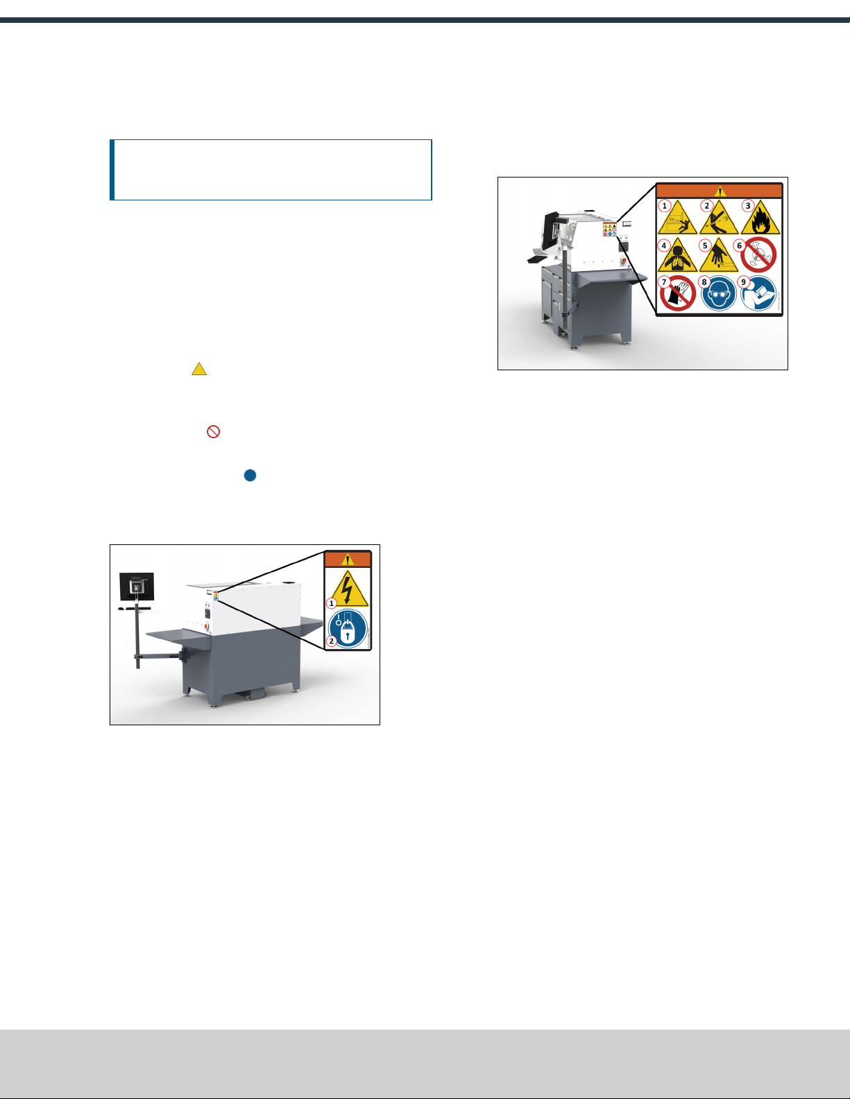
On the Electrical Cabinet Door
Figure 1-1: Example of a safety decal on the electrical
cabinet door.
1. WARNING! Electrocution Hazard. Points in the electrical
cabinet contain high voltages, which can electrocute or
shock you, causing death or serious injury. Even after the
machine is powered off, electronic devices in the
electrical cabinet can retain dangerous electrical
voltages. Use caution when servicing the machine inside
the electrical cabinet.
2. Lockout/Tagout. Before servicing the machine, you must
power off the machine and use an approved
lockout/tagout device to secure the Main Disconnect
switch in the OFF position. Points in the electrical
cabinet contain high voltages, which can electrocute or
shock you, causing death or serious injury.
Next to the Main Disconnect
Figure 1-2: Example of a safety decal next to the Main
Disconnect.
1. WARNING! Ejection Hazard. Fixtures, tooling,
workpieces, or other loose items can become dangerous
projectiles and can cause death or serious injury. Before
operating this machine in any way, you must verify that
you have appropriately secured all components.
2. WARNING! Loose Workpiece or Workholding Hazard.
You must verify that the workpieces are securely
clamped into the workholding device, and verify that the
workholding device is securely fastened.
3. WARNING! Fire Hazard. The machine and its enclosure
are not designed to contain fire or explosions. Only use
materials and coolants that are intended for the specific
machining operation. Never use flammable or explosive
items. Before operating the machine in any way, you
must read all Safety Data Sheets (SDSs) for any
workpiece materials, coatings, coolants, lubricants, and
other consumables used.
4. WARNING! Inhalation Hazard. The machine and its
enclosure do not protect you from airborne particulates.
Chips, dust, and vapors from certain materials can be
toxic or otherwise harmful. Before operating the
machine in any way, you must read all Safety Data
Sheets (SDSs) for any workpiece materials, coatings,
coolants, lubricants, and other consumables used.
5. WARNING! Cut Hazard. Tools and swarf can cut you.
Only hold tools by the tool holder. Before inserting or
removing tools from the machine, you must verify that
all motion is completely stopped.
©Tormach® 2021
Specifications subject to change without notice.
Page 13 UM10753: 8L Operator's Manual (Version 0321B)
For the most recent version, see tormach.com/support
6. Don't Use Extended Jaws. You must not use jaws other
than those made specifically for this machine. Extended
jaw can cause the jaws to break or the chuck to fail. If
you use extended jaws, there's a risk of property
damage, serious injury, or death.
7. Don't Wear Gloves. You must not operate this machine
while wearing gloves. If you do, the rotating components
could draw you into the machine while it's powered on
and operating.
8. Personal Protective Equipment:Eyes. Prevent injury by
always wearing protective safety eyewear. Before
operating this machine in any way, you must verify that
your eyewear is impact-resistant and rated for
ANSI787+.
9. Operator Knowledge. Before operating this machine in
any way, you and all other operators must read and
understand all instructions. If you don't, there's a risk of
voided warranty, property damage, serious injury, or
death.
On the Rear of the Headstock
Figure 1-3: Example of safety decals on the rear of the
headstock.
1. WARNING!Bar Whip Hazard. Unsupported bar stock
that extends from the rear of the drawtube can bend
during operation, causing it to whip unpredictably. Never
extend an unsupported bar stock past the left end of the
spindle bore. If you do, there's a risk of serious injury or
death.
2. WARNING! Entanglement / Entrapment Hazard. The
machine operates under automatic control — it can start
at any time and crush, cut, entangle, or pinch body
parts.Always keep clear of positions on the machine
where unexpected or unintended machine motion could
cause harm. Before operating this machine in any way,
you must verify that all operators know the location of
the machine's Emergency Stop button.
1.3.3 Information Decals
Before operating the machine in any way, you must locate and
become familiar with all installed information decals on the
machine and equipment.
Serial Number Plate
The serial number plate is on the side of the electrical cabinet,
near the Main Disconnect switch.
Figure 1-4: Example of the serial number plate on the side
of the electrical cabinet.
1.4 MACHINE SAFETY
Before operating the machine in any way, you must
read and understand this section.
Safe operation of the machine depends on its proper use and
the precautions you take. Only trained personnel — with a
clear and thorough understanding of its operation and safety
requirements — shall operate this machine.
1.4.1 General Shop Safety 14
1.4.2 Operational Safety 15
1.4.3 Electrical Safety 16
1.4.1 General Shop Safety
Verify that only qualified machinery maintenance
professionals install, set up, or perform maintenance on
this machine.
Keep the work area well-lit. Use additional lighting if
needed. The work area should be illuminated to a
minimum of 500 lx.
Keep the work area temperature- and humidity-controlled.
Remove loose-fitting clothing, neckties, gloves, and
jewelry.
©Tormach® 2021
Specifications subject to change without notice.
Page 14 UM10753: 8L Operator's Manual (Version 0321B)
For the most recent version, see tormach.com/support
1: SAFETY

1: SAFETY
Tie up long hair and secure it under a hat.
Wear safety eye protection rated for ANSI Z87+.
Wear closed-toed safety shoes.
Wear ear protection when you expect the machine or the
machining processes to exceed safe exposure limits.
Keep the work area clean and free of clutter. Machine
motion can occur if controls are accidentally activated.
Immediately clean up spills after they occur.
Never operate the machine after consuming alcohol or
taking medication that could prevent you from safely
operating the machine.
Never operate the machine while tired or otherwise
impaired.
Never operate the machine in an explosive (ATEX)
atmosphere. Such explosive atmospheres include
explosive gases, vapors, mists, powders, and dusts.
1.4.2 Operational Safety
General
Understand that the machine is automatically controlled
and can start at any time.
Become familiar with all physical and software controls.
Always use a chip scraper or brush when clearing away
chips, oil, or coolant.
Examine all tools, fixtures, workpieces, and guarding for
signs of damage. Replace any damaged components as
soon as you find them.
The enclosure and other guards may not stop all types of
projectiles, like broken tools or loose workpieces.
Stop the machine and verify that all machine motion has
completely stopped before doing any of the following:
Adjusting a part, fixture, or coolant nozzle.
Changing tools or parts.
Clearing away chips, oil, or coolant.
Reaching into any part of the machine's motion
envelope.
Removing protective shields or safeguards.
Taking measurements.
Doing any other action inside the machine enclosure.
Use flood or MQL (mist) coolant as required by the
machining operation.
Only use coolants designed for metal working applications
such as soluble oils, semi-synthetic, or synthetic coolants.
Read the Safety Data Sheet (SDS) for all workpiece
materials, coatings, coolants (flood or MQL), lubricants,
and other consumables. Chips, dust, and vapors from
certain materials can be toxic or otherwise harmful.
Dispose of scrap and swarf according to local regulations
and guidelines.
Thoroughly read all safety precautions and instructions.
When machining an unproven program, use feed, speed,
and maximum velocity overrides, Distance-to-Go (DTG)
displays, single block, feed hold, and other control
features.
Never enter the machining envelope.
Never reach around a guard.
Never allow the machine to run with the enclosure door
open.
Never allow the machine to run unattended.
Never obstruct the Emergency Stop button or any other
controls.
Never allow untrained operators to install, operate, or
maintain the machine.
Never modify, defeat, or bypass safety devices or
interlocks.
Never machine abrasive, carcinogenic, explosive,
flammable, radioactive, or toxic materials. Such materials
include, but are not limited to:
Beryllium and its alloys
Ceramic
Fiberglass
G10 fiberglass laminate
Graphite
Lead and its alloys
Magnesium and its alloys
Never allow swarf to accumulate on or within the
machine.
Never use flammable liquids (like alcohol, diesel fuel, or
kerosene) in the machine’s coolant system.
Never use water, coolants without rust inhibitors, or
straight cutting oil in the machine’s coolant system.
©Tormach® 2021
Specifications subject to change without notice.
Page 15 UM10753: 8L Operator's Manual (Version 0321B)
For the most recent version, see tormach.com/support

Tooling
Use appropriate speeds, feeds, and cutting parameters for
your machine, machine operation, material, and tooling.
Use tools and tool holders that are suitable for the current
operation.
Examine tools for signs of damage. Replace any damaged
tools as soon as you find them.
The enclosure and other guards may not stop all types of
projectiles, like broken tooling.
Never use unbalanced tooling or spindle fixtures.
Never use tools that are larger or longer than necessary.
Never use tools at speeds above their operational limits.
Workholding
Secure workpieces with appropriate workholding devices.
Verify that the workpiece is adequately secured.
Position clamps and workholding devices clear of any tool
paths.
Remove cutoff workpieces and other large chips before
starting the machine.
Never extend an unsupported bar stock past the left end of
the spindle bore.
Never machine any materials without first securing them
to the tailstock.
Never operate the machine with the tailstock removed.
Never leave tools, stock, or other loose items inside the
machine.
1.4.3 Electrical Safety
WARNING! Electrical Shock Hazard: You must power
off the machine before making any electrical
connections. If you don't, there's a risk of
electrocution or shock.
Power off the machine before servicing.
Use an approved lockout/tagout system to secure the
machine's Main Disconnect in the OFF position before
servicing the machine.
Understand that certain electrical components can retain
dangerous electrical voltages, even after the machine is
powered off and all power is removed from the system.
Understand that certain installation, maintenance, and
troubleshooting procedures — for the machine and certain
accessories — require access to or modification of wiring
inside of the electrical cabinet. Only qualified electrical
machinery technicians shall perform these procedures.
Confirm that the mains voltage conforms to requirements
before connecting the machine.
For more information, see "Electrical and Power
Requirements" (page20).
Confirm that the machine installation meets all codes and
regulations of your locality.
Confirm that electrical connections are performed by a
certified electrician.
Lock the electrical cabinet door and remove the keys when
the machine is not being serviced to prevent unqualified or
unauthorized personnel from accessing the electrical
cabinet.
Never operate the machine with the electrical cabinet
door open.
Never reach into the electrical cabinet with the machine
powered on.
Never modify the machine's electronics.
Never drill into the electrical cabinet.
©Tormach® 2021
Specifications subject to change without notice.
Page 16 UM10753: 8L Operator's Manual (Version 0321B)
For the most recent version, see tormach.com/support
1: SAFETY


2: ABOUT YOUR MACHINE
©Tormach® 2021
Specifications subject to change without notice.
Page 18 UM10753: 8L Operator's Manual (Version 0321B)
For the most recent version, see tormach.com/support
2.1 SPECIFICATIONS
Travels
X-Axis 4.5" (114 mm)
Z-Axis 10" (330 mm) with tailstock
Spindle
Spindle Speed lLow 180 rpm to 2500 rpm
lHigh 350 rpm to 5000 rpm
Through Spindle Bore 1" (26 mm)
Maximum Workpiece Length 10" (254 mm) with tailstock
Maximum Feed Rate
X- and Z-Axis 150 IPM (3.8 m/min)
Tailstock
Taper MT2
Diameter 0.9" (22 mm)
Travel 2.2" (55 mm)
Machine Specifications
Table Length 7.5"(191 mm)
Table Width 4"(102 mm)
Maximum Swing Over Bed 8.3" (210 mm)
Maximum Swing Over Carriage 4.1" (105 mm)
Machine Footprint 50"× 26" (1.2 m × 0.7 m)
Overall System Height 52"(1.3 m)
Typical System Weight 815 lb (370 kg)
Power
Primary Power Required Single-Phase 115 Vac, 50/60 Hz
Recommended Circuit Amperage Dedicated Dedicated 15 A breaker

SITE REQUIREMENTS
IN THIS SECTION, YOU'LL LEARN:
About the site requirements of this machine (including electrical and power requirements).
Before operating the machine in any way, you must read and understand this section.
CONTENTS
3.1 General Site and Space Requirements 20
3.2 Electrical and Power Requirements 20

3.1 GENERAL SITE AND SPACE REQUIREMENTS
When choosing a location for your machine, you must verify
that it meets all requirements outlined in this section.
3.1.1 Site Requirements
You must verify that the area:
lAllows for unrestricted access to machine controls.
lConforms to the following:
oPrimary Power RequiredSingle-Phase 115 Vac,
50/60 Hz
oRecommended Circuit AmperageDedicated 15 A
breaker
Note: For more information, see "Electrical and
Power Requirements" (below).
lHas clean, dry, compressed air.
Note: Compressed air is only required for
certain accessories.
lHas one continuous slab sufficient to support the weight
of the machine, accessories, and any additional
equipment.
lIs a dry, properly ventilated, and well-lit internal space
that conforms to the following temperature and
humidity requirements:
oOperating Temperature Range 40°F-100°F (5°C-
38°C)
oHumidity Range 5%-95% (non-condensing)
lProvides for unobstructed machine motion and
operation.
3.1.2 Space Requirements
The area must meet the following space requirements. Allow
more space to access the rear of the machine for maintenance
and repairs.
lMachine Size50"× 26" (1.2 m × 0.7 m)
lMachine Height52"(1.3 m)
Figure 3-1: Dimensions of the machine itself, as
viewed from the front.
lTypical System Footprint89"× 46" (2.3 m × 1.2 m)
Figure 3-2: Dimensions of the machine and it's
required added space, as viewed from above.
3.2 ELECTRICAL AND POWER REQUIREMENTS
You must verify that the site conforms to the following
electrical and power requirements. If it doesn't, you may
consider other options: go to "Options for Non-Conforming
Sites" (on the next page).
3.2.1 Electrical Requirements
A certified electrician must make all electrical connections,
and it's your responsibility to verify that the electrical
installation of the machine meets all local regulations and
electrical codes.
lPrimary Power RequiredSingle-Phase 115 Vac, 50/60
Hz
lRecommended Circuit AmperageDedicated 15 A
breaker
3.2.2 Power Requirements
If the site conforms to the electrical requirements, verify that
it meets the following power requirements:
lNo Electrical Noise Primary power must be provided
by a dedicated circuit, which must be isolated from
electrically-noisy devices like welders or plasma torches.
The machine should be isolated from inductive loads
from items like vacuum cleaners or air compressors.
©Tormach® 2021
Specifications subject to change without notice.
Page 20 UM10753: 8L Operator's Manual (Version 0321B)
For the most recent version, see tormach.com/support
3: SITE REQUIREMENTS
Table of contents
Other Tormach Lathe manuals


