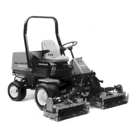
Toro 03170 User manual

FormNo.3363-312RevC
Reelmaster®3100-DTractionUnit
ModelNo.03170—SerialNo.310000001andUp
ModelNo.03171—SerialNo.310000001andUp
ModelNo.03172
ModelNo.03173
ToregisteryourproductordownloadanOperator'sManualorPartsCatalogatnocharge,gotowww.Toro.com.OriginalInstructions(EN)

Introduction
ThisproductcomplieswithallrelevantEuropean
directives,fordetailspleaseseetheseparateproduct
specicDeclarationofConformity(DOC)sheet.
WARNING
CALIFORNIA
Proposition65Warning
Dieselengineexhaustandsomeofits
constituentsareknowntotheStateof
Californiatocausecancer,birthdefects,
andotherreproductiveharm.
Thismachineisaride-on,reel-bladelawnmower
intendedtobeusedbyprofessional,hiredoperatorsin
commercialapplications.Itisprimarilydesignedfor
cuttinggrassonwell-maintainedlawnsinparks,golf
courses,sportselds,andoncommercialgrounds.Itis
notdesignedforcuttingbrush,mowinggrassandother
growthalongsidehighways,orforagriculturaluses.
Readthisinformationcarefullytolearnhowtooperate
andmaintainyourproductproperlyandtoavoidinjury
andproductdamage.Youareresponsibleforoperating
theproductproperlyandsafely.
YoumaycontactTorodirectlyatwww.Toro.comfor
productandaccessoryinformation,helpndingadealer,
ortoregisteryourproduct.
Wheneveryouneedservice,genuineToroparts,
oradditionalinformation,contactanAuthorized
ServiceDealerorToroCustomerServiceandhave
themodelandserialnumbersofyourproductready.
Figure1identiesthelocationofthemodelandserial
numbersontheproduct.Writethenumbersinthe
spaceprovided.
Figure1
1.Modelandserialnumberlocation
ModelNo.
SerialNo.
Thismanualidentiespotentialhazardsandhassafety
messagesidentiedbythesafetyalertsymbol(Figure2),
whichsignalsahazardthatmaycauseseriousinjury
ordeathifyoudonotfollowtherecommended
precautions.
Figure2
1.Safetyalertsymbol
Thismanualuses2otherwordstohighlightinformation.
Importantcallsattentiontospecialmechanical
informationandNoteemphasizesgeneralinformation
worthyofspecialattention.
Important:Thisengineisnotequippedwitha
sparkarrestermufer.ItisaviolationofCalifornia
PublicResourceCodeSection4442touseoroperate
theengineonanyforest-covered,brush-covered,or
grass-coveredland.Otherstatesorfederalareas
mayhavesimilarlaws.
©2012—TheToro®Company
8111LyndaleAvenueSouth
Bloomington,MN554202
Contactusatwww.Toro.com.
PrintedintheUSA
AllRightsReserved

Contents
Introduction.................................................................2
Safety...........................................................................4
SafeOperatingPractices.......................................4
ToroMowerSafety...............................................6
SoundPowerLevel...............................................8
SoundPressureLevel...........................................8
VibrationLevel....................................................8
SafetyandInstructionalDecals.............................8
Setup.........................................................................13
1InstallingtheWheels........................................14
2InstallingtheSteeringWheel............................14
3Activating,Charging,andConnectingthe
Battery...........................................................15
4CheckingtheAngleIndicator...........................16
5InstallingtheHoodLatch(CEOnly)................16
6InstallingtheExhaustGuard(CE
Only)..............................................................17
7InstallingtheRollBar.......................................18
8InstallingtheFrontLiftArms...........................18
9InstallingtheCarrierFramestotheCutting
Units..............................................................19
10MountingtheCuttingUnits............................21
11MountingtheCuttingUnitDrive
Motors...........................................................21
12AdjustingtheLiftArms.................................22
ProductOverview......................................................24
Controls.............................................................24
Specications.....................................................26
Attachments/Accessories...................................26
Operation...................................................................27
CheckingtheEngineOilLevel............................27
FillingtheFuelTank...........................................27
CheckingtheCoolingSystem..............................28
CheckingtheHydraulicSystem...........................29
CheckingtheTirePressure.................................30
CheckingtheReel-to-BedknifeContact...............30
TorquingtheWheelNuts....................................30
StartingandStoppingtheEngine........................30
BleedingtheFuelSystem....................................30
CheckingtheInterlockSystem............................31
TowingtheTractionUnit....................................31
StandardControlModule(SCM)........................32
OperatingTips...................................................34
Maintenance...............................................................39
RecommendedMaintenanceSchedule(s)................39
DailyMaintenanceChecklist...............................40
ServiceIntervalChart.........................................41
PremaintenanceProcedures....................................41
RemovingtheHood...........................................41
Lubrication.............................................................42
GreasingtheBearingsAndBushings...................42
SealedBearings...................................................44
EngineMaintenance...............................................45
ServicingtheAirCleaner....................................45
ChangingtheEngineOilandFilter.....................45
FuelSystemMaintenance.......................................46
ServicingtheFuelTank......................................46
InspectingtheFuelLinesand
Connections...................................................46
DrainingtheWaterSeparator..............................46
ChangingtheFuelFilterCanister........................47
BleedingAirfromtheInjectors...........................47
ElectricalSystemMaintenance................................48
CaringfortheBattery.........................................48
StoringtheBattery..............................................48
Fuses..................................................................48
DriveSystemMaintenance.....................................49
AdjustingtheTractionDriveforNeutral.............49
CoolingSystemMaintenance..................................49
CleaningtheEngineCoolingSystem...................49
BrakeMaintenance.................................................50
AdjustingtheParkingBrake................................50
BeltMaintenance....................................................51
ServicingtheEngineBelts..................................51
ControlsSystemMaintenance.................................52
AdjustingtheThrottle........................................52
HydraulicSystemMaintenance...............................52
ChangingtheHydraulicFluid.............................52
ChangingtheHydraulicFilter.............................53
CheckingtheHydraulicLinesandHoses.............54
MiscellaneousMaintenance....................................54
BacklappingtheCuttingSystem..........................54
Storage.......................................................................55
PreparationforSeasonalStorage.........................55
Schematics.................................................................57
3

Safety
ThismachinemeetsorexceedsCENstandardEN
836:1997(whenappropriatedecalsapplied),and
ANSIB71.4-2004specicationsineffectatthetime
ofproductionwhenequippedwithrequiredweights
aslistedintheweightchart.
Improperuseormaintenancebytheoperator
orownercanresultininjury.Toreducethe
potentialforinjury,complywiththesesafety
instructionsandalwayspayattentiontothesafety
alertsymbol,whichmeansCaution,Warning,or
Danger—personalsafetyinstruction.Failureto
complywiththeinstructionmayresultinpersonal
injuryordeath.
SafeOperatingPractices
ThefollowinginstructionsarefromtheCENstandard
EN836:1997,ISOstandard5395:1990,andANSI
B71.4-2004.
Training
•ReadtheOperator’sManualandothertrainingmaterial
carefully.Befamiliarwiththecontrols,safetysigns,
andtheproperuseoftheequipment.
•Iftheoperatorormechaniccannotreadthelanguage
ofthismanual,itistheowner’sresponsibilityto
explainthismaterialtothem.
•Neverallowchildrenorpeopleunfamiliarwiththese
instructionstouseorservicethemower.Local
regulationsmayrestricttheageoftheoperator.
•Nevermowwhilepeople,especiallychildren,orpets
arenearby.
•Keepinmindthattheoperatororuserisresponsible
foraccidentsorhazardsoccurringtootherpeopleor
theirproperty.
•Donotcarrypassengers.
•Alldriversandmechanicsshouldseekandobtain
professionalandpracticalinstruction.Theowneris
responsiblefortrainingtheusers.Suchinstruction
shouldemphasizethefollowing:
–Theneedforcareandconcentrationwhen
workingwithride-onmachines
–Controlofaride-onmachineslidingonaslope
willnotberegainedbytheapplicationofthe
brake.Themainreasonsforlossofcontrolare
asfollows:
◊Insufcientwheelgrip
◊Beingdriventoofast
◊Inadequatebraking
◊Thetypeofmachineisunsuitableforthetask
◊Lackofawarenessoftheeffectofground
conditions,especiallyslopes
◊Incorrecthitchingandloaddistribution
Preparation
•Whilemowing,alwayswearsubstantialfootwear,
longtrousers,hardhat,safetyglasses,andhearing
protection.Longhair,looseclothing,orjewelrymay
gettangledinmovingparts.Donotoperatethe
equipmentwhenbarefootorwearingopensandals.
•Thoroughlyinspecttheareawheretheequipment
istobeusedandremoveallobjectswhichmaybe
thrownbythemachine.
•Warning—Fuelishighlyammable.Takethe
followingprecautions:
–Storefuelincontainersspecicallydesignedfor
thispurpose.
–Refueloutdoorsonlyanddonotsmokewhile
refueling.
–Addfuelbeforestartingtheengine.Never
removethecapofthefueltankoraddfuelwhile
theengineisrunningorwhentheengineishot.
–Iffuelisspilled,donotattempttostartthe
enginebutmovethemachineawayfromthe
areaofspillageandavoidcreatinganysourceof
ignitionuntilfuelvaporshavedissipated.
–Replaceallfueltankandcontainercapssecurely.
•Replacefaultysilencers/mufers.
•Evaluatetheterraintodeterminewhataccessories
andattachmentsareneededtoproperlyand
safelyperformthejob.Onlyuseaccessoriesand
attachmentsapprovedbythemanufacturer.
•Checkthatoperator’spresencecontrols,safety
switchesandshieldsareattachedandfunctioning
properly.Donotoperateunlesstheyarefunctioning
properly.
Operation
•Donotoperatetheengineinaconnedspacewhere
dangerouscarbonmonoxidefumescancollect.
•Mowonlyindaylightoringoodarticiallight.
•Beforeattemptingtostarttheengine,disengageall
bladeattachmentclutches,shiftintoneutral,and
engagetheparkingbrake.Onlystarttheenginefrom
4

theoperator’sposition.NeverremovetheROPSand
alwaysweartheseatbeltsduringoperation.
•Rememberthereisnosuchthingasasafeslope.
Travelongrassslopesrequiresparticularcare.Do
thefollowingtoguardagainstoverturning:
–Donotstoporstartsuddenlywhengoingupor
downhill.
–Keepmachinespeedslowonslopesandduring
tightturns.
–Stayalertforhumpsandhollowsandother
hiddenhazards.
–Nevermowacrossthefaceoftheslope,unless
themowerisdesignedforthispurpose.
•Stayalertforholesintheterrainandotherhidden
hazards.
•Watchoutfortrafcwhencrossingornearroadways.
•Stopthebladesfromrotatingbeforecrossing
surfacesotherthangrass.
•Whenusinganyattachments,neverdirectdischarge
ofmaterialtowardbystandersnorallowanyonenear
themachinewhileinoperation.
•Neveroperatethemachinewithdamagedguards,
shields,orwithoutsafetyprotectivedevicesinplace.
Besureallinterlocksareattached,adjustedproperly,
andfunctioningproperly.
•Donotchangetheenginegovernorsettingsor
overspeedtheengine.Operatingtheengineat
excessivespeedmayincreasethehazardofpersonal
injury.
•Dothefollowingbeforeleavingtheoperator’s
position:
–Stoponlevelground.
–Disengagethepowertake-offandlowerthe
attachments.
–Changeintoneutralandsettheparkingbrake.
–Stoptheengineandremovethekey.
•Disengagethedrivetoattachments,stopthe
engine,andremovetheignitionkeyinthefollowing
conditions:
–Beforerefueling
–Beforeremovingthegrasscatcher(s)
–Beforemakingheightadjustments,unlessthe
adjustmentcanbemadefromtheoperator’s
position.
–Beforeclearingblockages
–Beforechecking,cleaning,orworkingonthe
mower
–Afterstrikingaforeignobjectorifanabnormal
vibrationoccurs(checkimmediately).Inspect
themowerfordamageandmakerepairsbefore
restartingandoperatingtheequipment.
•Disengagethedrivetoattachmentswhen
transportingorwhenthemachineisnotinuse.
•Reducethethrottlesettingbeforestoppingthe
engineand,iftheengineisprovidedwithafuel
shut-offvalve,turnthefueloffattheconclusionof
mowing.
•Keephandsandfeetawayfromthecuttingunits.
•Lookbehindanddownbeforebackinguptobesure
ofaclearpath.
•Slowdownandusecautionwhenmakingturnsand
crossingroadsandsidewalks.Stopcylinders/reels
ifnotmowing.
•Donotoperatethemowerundertheinuenceof
alcoholordrugs.
•Lightningcancausesevereinjuryordeath.If
lightningisseenorthunderisheardinthearea,do
notoperatethemachine;seekshelter.
•Usecarewhenloadingorunloadingthemachine
intoatrailerortruck.
•Theoperatorshallturnonashingwarninglights,
ifprovided,whenevertravelingonapublicroad,
exceptwheresuchuseisprohibitedbylaw.
•Usecarewhenapproachingblindcorners,shrubs,
trees,orotherobjectsthatmayobscurevision.
MaintenanceandStorage
•Keepallnuts,boltsandscrewstighttobesurethe
equipmentisinsafeworkingcondition.
•Neverstoretheequipmentwithfuelinthetank
insideabuildingwherefumesmayreachanopen
ameorspark.
•Allowtheenginetocoolbeforestoringinany
enclosure.
•Toreducetherehazard,keeptheengine,
silencer/mufer,batterycompartmentfuelstorage
area,cuttingunitsanddrivesfreeofgrass,leaves,or
excessivegrease.Cleanupoilorfuelspillage.
•Keepallpartsingoodworkingconditionandall
hardwareandhydraulicttingstightened.Replace
wornordamagedpartsanddecalsforsafety.
•Ifthefueltankhastobedrained,dothisoutdoors.
•Becarefulduringadjustmentofthemachineto
prevententrapmentofthengersbetweenmoving
bladesandxedpartsofthemachine.
5

•Onmulti-cylinder/multi-reelmachines,takecare
asrotatingonecylinder/reelcancauseother
cylinders/reelstorotate.
•Disengagedrives,lowerthecuttingunits,setparking
brake,stopengineandremovekey.Waitforall
movementtostopbeforeadjusting,cleaningor
repairing.
•Cleangrassanddebrisfromcuttingunits,drives,
silencers/mufers,andenginetohelppreventres.
Cleanupoilorfuelspillage.
•Shutofffuelwhilestoringortransporting.Donot
storefuelnearames.
•Parkthemachineonlevelground.
•Neverallowuntrainedpersonneltoservicethe
machine.
•Usejackstandstosupportcomponentswhen
required.
•Carefullyreleasepressurefromcomponentswith
storedenergy.
•Disconnectbatterybeforemakinganyrepairs.
Disconnectthenegativeterminalrstandthe
positivelast.Reconnectpositiverstandnegative
last.
•Usecarewhencheckingthecylinders/reels.Wear
glovesandusecautionwhenservicingthem.
•Keephandsandfeetawayfrommovingparts.If
possible,donotmakeadjustmentswiththeengine
running.
•Chargebatteriesinanopenwellventilatedarea,
awayfromsparkandames.Unplugchargerbefore
connectingordisconnectingfrombattery.Wear
protectiveclothinganduseinsulatedtools.
ToroMowerSafety
Thefollowinglistcontainssafetyinformationspecic
toToroproductsorothersafetyinformationthatyou
mustknowthatisnotincludedintheCEN,ISO,or
ANSIstandards.
Thisproductiscapableofamputatinghandsand
feetandthrowingobjects.Alwaysfollowallsafety
instructionstoavoidseriousinjuryordeath.
Useofthisproductforpurposesotherthanitsintended
usecouldprovedangeroustouserandbystanders.
WARNING
Engineexhaustcontainscarbonmonoxide,which
isanodorless,deadlypoisonthatcankillyou.Do
notrunengineindoorsorinanenclosedarea.
Preparation
Besuretoestablishyourownspecialproceduresand
workrulesforunusualoperatingconditions(e.g.,
slopestoosteepforoperation).Surveythecomplete
mowingsitetodeterminewhichhillscanbesafely
operatedon.Whenperformingthissitesurvey,always
usecommonsenseandtakeintoconsiderationtheturf
conditionandtherolloverrisk.Todeterminewhichhills
orslopesmaybesafelyoperatedon,usetheinclinometer
providedwitheachmachine.Toperformasitesurvey,
followtheprocedureoutlinedintheOperationsection
ofthethismanual.Themaximumsidehillangleis
detailedontheslopedecalafxedneartheangle
indicator.
Training
Theoperatormustbeskilledandtrainedinhowtodrive
onhillsides.Failuretousecautiononslopesorhills
maycausethevehicletotiporroll,possiblyresulting
inpersonalinjuryordeath.
Operation
•Knowhowtostopthemachineandenginequickly.
•Donotoperatethemachinewhilewearingtennis
shoesorsneakers.
•Wearingsafetyshoesandlongpantsisadvisableand
requiredbysomelocalordinancesandinsurance
regulations.
•Keephands,feet,andclothingawayfrommoving
partsandthemowerdischargearea.
•Fillthefueltankuntillevelis1/2inch(12mm)
belowthebottomofthellerneck.Donotoverll.
•Checkthesafetyinterlockswitchesdailyforproper
operation.Ifaswitchshouldfail,replacetheswitch
beforeoperatingthemachine.
•Whenstartingtheengine,engagetheparkingbrake,
putthetractionpedalinneutral,anddisengage
thebladedrive.Aftertheenginestarts,releasethe
parkingbrakeandkeepyourfootoffofthetraction
pedal.Themachinemustnotmove.Ifmovement
isevident,refertotheMaintenancesectionofthis
manualtoadjustthetractiondrive.
•Useextremecautionwhenoperatingclosetosand
traps,ditches,creeks,steephillsides,orotherhazards.
•Reducespeedwhenmakingsharpturns.
•Donotturnonhills.
•Iftheenginestallsorlosesheadwayandcannotmake
ittothetopofaslope,donotturnthemachine
around.Alwaysbackslowly,straightdowntheslope.
6

•Donotoperateonasidehillthatistoosteep.A
rollovermayoccurbeforelosingtraction.
•Model03171-Theslopeangleatwhichthemachine
willtipisdependentonmanyfactors.Amongthese
aremowingconditionssuchaswetorundulating
terrain,speed(especiallyinturns),positionofthe
cuttingunits(withtheSidewinder),tirepressure,
andoperatorexperience.Atsidehillanglesof15
degreesorless,theriskofarolloverislow .Asthe
slopeangleincreasestoarecommendedmaximum
limitof20degrees,theriskofarolloverincreasesto
amoderatelevel.Donotexceeda20degreeside
hillslopeanglebecausetheriskofarolloverand
seriousinjuryordeathisveryhigh.
•Model03170-Theslopeangleatwhichthemachine
willtipisdependentonmanyfactors.Amongthese
aremowingconditionssuchaswetorundulating
terrain,speed(especiallyinturns),positionofthe
cuttingunits,tirepressure,andoperatorexperience.
Atsidehillanglesof20degreesorless,theriskof
arolloverislow.Astheslopeangleincreasestoa
recommendedmaximumlimitof25degrees,therisk
ofarolloverincreasestoamoderatelevel.Donot
exceeda25degreesidehillslopeanglebecause
theriskofarolloverandseriousinjuryordeath
isveryhigh.
•Forsteeringcontrol,lowerthecuttingunitswhen
goingdownslopes.
•Avoidsuddenstopsandstarts.
•Usethereversepedalforbraking.
•Watchfortrafcwhennearorcrossingroads.
Alwaysyieldtheright-of-way.
•Raisethecuttingunitswhendrivingfromonework
areatoanother.
•Donottouchtheengine,mufer,exhaustpipe,or
hydraulictankwhiletheengineisrunningorsoon
afterithasstoppedbecausetheseareascouldbehot
enoughtocauseburns.
•Thismachineisnotdesignedorequippedfor
on-roaduseandisaslow-movingvehicle.Ifyou
mustcrossortravelonapublicroad,youshould
beawareofandcomplywithlocalregulations,such
asrequiredlights,slowmovingvehiclesigns,and
reectors.
•Thegrassbasketsmustbeinplaceduringoperation
ofthecylinders/reelsorthatchersformaximum
safety.Shuttheengineoffbeforeemptyingthe
baskets.
•Whenapersonorpetappearsunexpectedlyinor
nearthemowingarea,stopmowing.Careless
operation,combinedwithterrainangles,ricochets,
orimproperlypositionedguardscanleadtothrown
objectinjuries.Donotresumemowinguntilthe
areaiscleared.
MaintenanceandStorage
•Beforeservicingormakingadjustments,stopthe
engineandremovetheignitionkey.
•Ensurethattheentiremachineisproperlymaintained
andingoodoperatingcondition.Frequentlycheck
allnuts,bolts,screws,andhydraulicttings.
•Makesureallhydrauliclineconnectorsaretightand
allhydraulichosesandlinesareingoodcondition
beforeapplyingpressuretothesystem.
•Keepyourbodyandhandsawayfrompinhole
leaksornozzlesthatejecthydraulicuidunderhigh
pressure.Usepaperorcardboard,notyourhands,
tosearchforleaks.Hydraulicuidescapingunder
pressurecanhavesufcientforcetopenetratethe
skinandcauseseriousinjury.Ifuidisinjectedinto
theskinitmustbesurgicallyremovedwithinafew
hoursbyadoctorfamiliarwiththisformofinjury
organgrenemayresult.
•Checkallfuellinesfortightnessandwearona
regularbasis.Tightenorrepairthemasneeded.
•Beforedisconnectingorperforminganyworkon
thehydraulicsystem,allpressureinthesystemmust
berelievedbystoppingtheengineandloweringthe
cuttingunitstotheground.
•Iftheenginemustberunningtoperforma
maintenanceadjustment,keephands,feet,clothing,
andanypartsofthebodyawayfromthecutting
units,attachments,andanymovingparts.Keep
everyoneaway.
•Donotoverspeedtheenginebychanginggovernor
settings.Toensuresafetyandaccuracy,havean
AuthorizedToroDistributorcheckthemaximum
enginespeedwithatachometer.
•Theenginemustbeshutoffbeforecheckingtheoil
oraddingoiltothecrankcase.
•Ifmajorrepairsareeverneededorifassistanceis
desired,contactanAuthorizedToroDistributor.
•Toensureoptimumperformanceandcontinued
safetycerticationofthemachine,useonly
genuineTororeplacementpartsandaccessories.
Replacementpartsandaccessoriesmadebyother
manufacturerscouldbedangerous,andsuchuse
couldvoidtheproductwarranty.
7

SoundPowerLevel
Thisunithasaguaranteedsoundpowerlevelof96dBA,
whichincludesanUncertaintyValue(K)of1dBA.
Soundpowerlevelwasdeterminedaccordingtothe
proceduresoutlinedinISO11094.
SoundPressureLevel
Thisunithasasoundpressurelevelattheoperator’s
earof82dBA,whichincludesanUncertaintyValue(K)
of1dBA.
Soundpressurelevelwasdeterminedaccordingtothe
proceduresoutlinedinEN836.
VibrationLevel
Hand-Arm
Measuredvibrationlevelforrighthand=.41m/s2
Measuredvibrationlevelforlefthand=.52m/s2
UncertaintyValue(K)=0.5m/s2
Measuredvaluesweredeterminedaccordingtothe
proceduresoutlinedinEN836.
WholeBody
Measuredvibrationlevel=.49m/s2
UncertaintyValue(K)=0.5m/s2
Measuredvaluesweredeterminedaccordingtothe
proceduresoutlinedinEN836.
SafetyandInstructionalDecals
Safetydecalsandinstructionsareeasilyvisibletotheoperatorandarelocatednearanyareaof
potentialdanger.Replaceanydecalthatisdamagedorlost.
93-6681
1.Cutting/dismemberment—hazard,fan-stayawayfrom
movingparts.
93-7276
1.Explosionhazard—weareyeprotection.
2.Causticliquid/chemicalburnhazard—toperformrstaid,
ushwithwater.
3.Firehazard—nore,openames,orsmoking.
4.Poisonhazard—keepchildrenasafedistancefromthe
battery.
94-3353
Model03207only
1.Crushinghazardofhand—keepyourhandsasafedistance
away.
99-3444
99-3444
1.Reelspeed—fast2.Reelspeed—slow
99-3496
8

99-3558
CEonly
1.Warning—readtheOperator’sManual.
2.Tostarttheengine,sitontheseatandrotatetheignition
keytoOn/Preheatuntiltheglowplugindicatorlightgoes
out.Rotatethekeytostartanddisengagetheparking
brake.ReadtheOperator’sManualforfurtherinstructions.
3.Tostoptheengine,disengagethecuttingunits,rotatethe
ignitionkeytoOff,andremovethekey.Engagetheparking
brake.ReadtheOperator’sManualforfurtherinstructions.
100-4837
104-5181
CEonly
1.Warning—readtheOperator’sManual.
2.Tippinghazard—donotdriveonslopesgreaterthan15
degreesand,iftherollbarisinstalled,weartheseatbelt.
3.Thrownobjecthazard—keepbystandersasafedistance
fromthemachine.
4.Cuttinghazardofhandorfoot—stayawayfrommoving
parts.
5.Warning—locktheparkingbrake,stoptheengine,and
removetheignitionkeybeforeleavingthemachine.
106-6754
1.Warning—donottouchthehotsurface.
2.Cutting/dismembermenthazard,fanandentanglement
hazard,belt—stayawayfrommovingparts.
107-7801(CEonly)
Thissafetydecalincludesaslopewarningrequired
onthemachineforcompliancetotheEuropeanLawn
MowerSafetyStandardEN836:1997.Theconservative
maximumslopeanglesindicatedforoperationof
thismachineareprescribedbyandrequiredbythis
standard.
1.Tippinghazard—donotdriveonslopesgreaterthan15
degrees.
9

104-5192
Model03207only
1.Engagethepowertakeoff
(PTO).
5.Raisethecuttingunits.9.Engine—run13.Slow
2.Disengagethepowertake
off(PTO).
6.Movethecuttingunitsto
theleft.
10.Engine—start
3.Lowerthecuttingunits.7.Moverearwardtolockthe
liftlever.
11.Fast
4.Movethecuttingunitsto
theright.
8.Engine—stop12.Continuousvariablesetting
10

104-5193
Model03206only
1.Engagethepowertakeoff
(PTO).
5.Raisethecuttingunits.9.Engine—run13.Slow
2.Disengagethepowertake
off(PTO).
6.Movethecuttingunitsto
theleft.
10.Engine—start
3.Lowerthecuttingunits.7.Moverearwardtolockthe
liftlever.
11.Fast
4.Movethecuttingunitsto
theright.
8.Engine—stop12.Continuousvariablesetting
117-5104
11

BatterySymbols
Someorallofthesesymbolsareonyourbattery
1.Explosionhazard6.Keepbystandersasafe
distancefromthebattery.
2.Nore,opename,or
smoking.
7.Weareyeprotection;
explosivegasescan
causeblindnessandother
injuries
3.Causticliquid/chemical
burnhazard
8.Batteryacidcancause
blindnessorsevereburns.
4.Weareyeprotection9.Flusheyesimmediately
withwaterandgetmedical
helpfast.
5.ReadtheOperator's
Manual.
10.Containslead;donot
discard.
12

Setup
LooseParts
Usethechartbelowtoverifythatallpartshavebeenshipped.
ProcedureDescriptionQty.Use
Frontwheelassemblies2
1Rearwheelassembly1Installthewheels.
Steeringwheel1
Steeringwheelcap1
Largewasher1
Jamnut1
2
Screw1
Installthesteeringwheel.
3ElectrolyteA/RActivate,charge,andconnectthe
battery.
4Inclinometer1Checktheangleindicator.
Lockbracket1
Rivet2
Washer1
Screw,1/4x2inches1
5
Locknut,1/4inch1
InstalltheHoodLatch(CE).
Exhaustguard1
6Self-tappingscrew4InstalltheExhaustGuard(CE).
Rollbarassembly1
Flangeheadbolts4
Locknuts4
7Hoseclamp1
Installtherollbar.
Liftarms2
Pivotrod2
8Bolt(5/16x7/8inch)2
Installthefrontliftarms.(Partssupplied
intheLiftArmKit.)
9Nopartsrequired–Installthecarrierframestothecutting
units.
10Nopartsrequired–Mountthecuttingunits.
11Nopartsrequired–Mountthecuttingunitdrivemotors.
12Nopartsrequired–Adjusttheliftarms.
13

MediaandAdditionalParts
DescriptionQty.Use
Decal,CE6AfxtothemachineovercorrespondingEnglishdecals
forEuropeancompliance.
Ignitionkey2Starttheengine.
Operator'sManual1
EngineOperator'sManual1Readbeforeoperatingthemachine.
PartsCatalog1Usetolookupandorderparts.
OperatorTrainingMaterial1Viewbeforeoperatingthemachine.
Pre-deliverychecklist1Checktoensurethatthemachinehasbeenproperlyset
up.
Certicateofcompliance1EnsureCEcompliance.
Note:Determinetheleftandrightsidesofthemachine
fromthenormaloperatingposition.
1
InstallingtheWheels
Partsneededforthisprocedure:
2Frontwheelassemblies
1Rearwheelassembly
Procedure
1.Mountawheelassemblyontoeachwheelhub(valve
stemoutward).
Important:Thereartirehasanarrowerrim
thanthefronttires.
2.Installlugnutsandtorqueto45to65ft-lb(61to
88N-m).
2
InstallingtheSteeringWheel
Partsneededforthisprocedure:
1Steeringwheel
1Steeringwheelcap
1Largewasher
1Jamnut
1Screw
Procedure
1.Slidethesteeringwheelontothesteeringshaft
(Figure3).
Figure3
1.Steeringwheel3.Jamnut
2.Washer4.Cap
2.Slidethewasherontothesteeringshaft(Figure3).
14

3.Securethesteeringwheeltotheshaftwithajam
nutandtightenitto20to26ft-lb(27to35N-m)
(Figure3).
4.Installthecaptothesteeringwheelandsecureit
withascrew(Figure3).
3
Activating,Charging,and
ConnectingtheBattery
Partsneededforthisprocedure:
A/RElectrolyte
Procedure
WARNING
CALIFORNIA
Proposition65Warning
Batteryposts,terminals,andrelated
accessoriescontainleadandleadcompounds,
chemicalsknowntotheStateofCalifornia
tocausecancerandreproductiveharm.
W ash hands after handling .
Note:Ifthebatteryisnotlledwithelectrolyteor
activated,bulkelectrolytewith1.260specicgravity
mustbepurchasedfromalocalbatterysupplyoutlet
andaddedtothebattery.
DANGER
Batteryelectrolytecontainssulfuricacidwhichisa
deadlypoisonandcausessevereburns.
•Donotdrinkelectrolyteandavoidcontactwith
skin,eyes,orclothing.Wearsafetyglassesto
shieldyoureyesandrubberglovestoprotect
yourhands.
•Fillthebatterywherecleanwaterisalways
availableforushingtheskin.
1.Purchasebulkelectrolytewith1.260specicgravity
fromalocalbatterysupplyoutlet.
2.Openthehood.
3.Removethebatterycover(Figure4).
Figure4
1.Batterycover
4.Removethellercapsfromthebatteryandslowly
lleachcelluntilelectrolyteisjustabovetheplates.
5.Installthellercapsandconnecta3to4ampbattery
chargertothebatteryposts.Chargethebatteryata
rateof3to4ampsfor4to8hours.
WARNING
Chargingthebatteryproducesgassesthatcan
explode.
•Keepsparksandamesawayfrombattery.
•Neversmokenearthebattery.
6.Whenthebatteryischarged,disconnectthecharger
fromtheelectricaloutletandbatteryposts.
7.Removethellercaps.Slowlyaddelectrolyteto
eachcelluntilthelevelisuptothellring.Install
thellercaps.
Important:Donotoverllthebattery.
Electrolytewilloverowontootherpartsofthe
machineandseverecorrosionanddeterioration
willresult.
8.Installthepositivecable(red)tothepositive(+)
terminalandthenegativecable(black)tothe
negative(–)terminalofthebatteryandsecurethem
withboltsandnuts(Figure5).Makesurethatthe
positive(+)terminalisallofthewayontothepost
andthecableispositionedsnugtothebattery.The
cablemustnotcontactthebatterycover.
15

WARNING
Incorrectbatterycableroutingcoulddamage
thetractorandcablescausingsparks.Sparks
cancausethebatterygassestoexplode,
resultinginpersonalinjury.
•Alwaysdisconnectthenegative(black)
batterycablebeforedisconnectingthe
positive(red)cable.
•Alwaysconnectthepositive(red)battery
cablebeforeconnectingthenegative(black)
cable.
Figure5
1.Positive(+)batterycable2.Negative(–)batterycable
Important:Ifthebatteryiseverremoved,make
surethatthebatteryclampboltsareinstalled
withtheboltheadspositionedonthebottom
sideandthenutsonthetopside.Iftheclamp
boltsarereversed,theymayinterferewiththe
hydraulictubeswhenshiftingthecuttingunits.
9.CoatbothbatteryconnectionswithGrafo112X
(skinover)grease,ToroPartNo.505-47,petroleum
jelly,orlightgreasetopreventcorrosion.
10.Slidetherubberbootoverthepositiveterminalto
preventapossibleshortfromoccurring.
11.Installthebatterycover.
4
CheckingtheAngleIndicator
Partsneededforthisprocedure:
1Inclinometer
Procedure
DANGER
Toreduceriskofinjuryordeathduetorollover,do
notoperatethemachineonsidehillssteeperthan
25º.
1.Parkthemachineonaat,levelsurface.
2.Verifythatthemachineislevelbyplacingahand
heldinclinometer(suppliedwiththemachine)on
theframecrossrail,bythefueltank(Figure6).The
inclinometershouldreadzerodegreeswhenviewed
fromtheoperator’sposition.
Figure6
1.Angleindicator
3.Iftheinclinometerdoesnotreadzerodegrees,
movethemachinetoalocationwhereazerodegree
readingisobtained.Theangleindicator,mountedon
themachine,shouldnowreadzerodegreesaswell.
4.Iftheangleindicatordoesnotreadzerodegrees,
loosenthetwoscrewsandnutssecuringtheangle
indicatortothemountingbracket,adjustthe
indicatortoobtainazerodegreereading,andtighten
thebolts.
16

5
InstallingtheHoodLatch(CE
Only)
Partsneededforthisprocedure:
1Lockbracket
2Rivet
1Washer
1Screw,1/4x2inches
1Locknut,1/4inch
Procedure
1.Unhookthehoodlatchfromthehoodlatchbracket.
2.Removethe(2)rivetssecuringthehoodlatchbracket
tothehood(Figure7).Removethehoodlatch
bracketfromthehood.
G012628
1
2
Figure7
1.Hoodlatchbracket2.Rivets
3.Whilealigningthemountingholes,positiontheCE
lockbracketandthehoodlatchbracketontothe
hood.Thelockbracketmustbeagainstthehood
(Figure8).Donotremoveboltandnutassembly
fromthelockbracketarm.
G012629
1
2
Figure8
1.CElockbracket2.Boltandnutassembly
4.Alignthewasherswiththeholesontheinsideofthe
hood.
5.Rivetthebracketsandthewasherstothehood
(Figure8).
6.Hookthelatchontothehoodlatchbracket
(Figure9).
G012630
1
Figure9
1.Hoodlatch
7.Screwtheboltintotheotherarmofhoodlock
brackettolockthelatchinposition(Figure10).
Tightenboltsecurelybutdonottightennut.
G012631
1
2
3
Figure10
1.Bolt3.Armofhoodlockbracket
2.Nut
17

6
InstallingtheExhaustGuard
(CEOnly)
Partsneededforthisprocedure:
1Exhaustguard
4Self-tappingscrew
Procedure
1.Positiontheexhaustguardaroundthemuferwhile
aligningthemountingholeswiththeholesinthe
frame(Figure11).
Figure11
1.Exhaustguard
2.Securetheexhaustguardtotheframewith4
self-tappingscrews(Figure11).
7
InstallingtheRollBar
Partsneededforthisprocedure:
1Rollbarassembly
4Flangeheadbolts
4Locknuts
1Hoseclamp
Procedure
Important:Neverweldormodifyarollover
protectionsystem(ROPS).Replaceadamaged
ROPS,donotrepairorrevise.Anyalterationofa
ROPSmustbeapprovedbythemanufacturer.
1.Lowertherollbarontothetractionunitmounting
brackets,aligningthemountingholes.Ensurethat
theventtubeontherollbarisontheleftsideof
themachine(Figure12).
Figure12
1.ROPS4.Fuellineventtubehose
2.Mountingbracket5.Hoseclamp
3.Venttube
2.Secureeachsideoftherollbartothemounting
bracketswith2angeheadboltsandlocknuts
(Figure12).Torquethefastenersto60ft-lb(81
N-m).
3.Securethefuellineventhosetotheventtubeonthe
rollbarwiththehoseclamp.
CAUTION
Youmustconnectthefuellineventhosetothe
venttubepriortostartingtheengineorfuelwill
owfromthehose.
18

8
InstallingtheFrontLiftArms
Partsneededforthisprocedure:
2Liftarms
2Pivotrod
2Bolt(5/16x7/8inch)
Procedure
1.Removethe2boltsthatsecuretheliftarmpivot
shaftlinktotheliftarmpivotshafts,andremoveand
retainthepivotshaftlinkandbolts(Figure13).
Figure13
1.Liftarm,pivotshaftlink2.Liftarmpivotshaft
2.Insertapivotrodintoeachliftarmandalignthe
mountingholes(Figure14).
Figure14
1.Liftarm2.Pivotrod
3.Securethepivotrodstotheliftarmswith2bolts
(5/16x7/8inch).
4.Inserttheliftarmsontotheliftarmpivotshafts
(Figure15),andsecureeachwithaliftarmpivot
shaftlinkandboltspreviouslyremoved.
Note:Torquetheboltsto70ft-lb(95N-m).
Figure15
1.Liftarm,right4.Liftcylinder
2.Retainingring5.Spacers(2)
3.Liftarm,left6.Mountingpin
5.Removetherearretainingringssecuringthe
mountingpinstoeachendoftheliftcylinder.
6.Securetherightendoftheliftcylindertotheright
liftarmwithapinand2spacers((Figure15),).
Secureitwitharetainingring.
7.Securetheleftendoftheliftcylindertotheleftlift
armwithapin.Secureitwitharetainingring.
9
InstallingtheCarrierFrames
totheCuttingUnits
NoPartsRequired
Procedure
1.Removethecuttingunitsfromthecartons.Adjust
themasdescribedintheCuttingUnitOperator’s
Manual.
2.Positionafrontcarrierframe(Figure16)ontoeach
frontcuttingunit.
19

Figure16
1.Frontcarrierframe
3.Securethemountinglinkstothefrontcarrierframes
asfollows:
•Securethefrontmountinglinkstothemiddle
carrierframeholeswithabolt(3/8x2-1/4
inch),2atwashers,andalocknut,asshownin
Figure17.Positionawasheroneachsideofthe
linkwhenmounting.Torquethefastenersto31
ft-lb(42N-m).
•Securetherearmountinglinkstothemiddle
carrierframeholeswithabolt(3/8x2-1/4
inch),2atwashers,andalocknut,asshownin
Figure17.Positionawasheroneachsideofthe
linkwhenmounting.Torquethefastenersto31
ft-lb(42N-m).
Figure17
1.Frontcarrierframe
2.Frontmountinglink
3.Rearmountinglink
4.Positiontherearcarrierframe(Figure18)ontothe
rearcuttingunit.
Figure18
1.Rearcarrierframe
5.Securethemountinglinkstotherearcarrierframe
asfollows:
•Securethefrontmountinglinkstothecarrier
frameholeswithabolt(3/8x2-1/4inch),2at
washers,andalocknut,asshowninFigure19.
Positionawasheroneachsideofthelinkwhen
mounting.Torquethefastenersto31ft-lb(42
N-m).
•Securetherearmountinglinkstotherearcarrier
frameholeswithabolt(3/8x2-1/4inch),2at
washers,andalocknut,asshowninFigure19.
Positionawasheroneachsideofthelinkwhen
mounting.Torquethefastenersto31ft-lb(42
N-m).
20
This manual suits for next models
4
Table of contents
Other Toro Lawn Mower manuals
Popular Lawn Mower manuals by other brands

Snapper
Snapper 1600 Series Service manual

Dixon
Dixon ZTR 8000 Series Operator's manual

Weed Eater
Weed Eater WET17H42STA owner's manual

Grizzly
Grizzly ARM 4041 Lion Set Translation of the original instructions for use

MTD
MTD 445-E458 Illustrate parts list

AGCO Allis
AGCO Allis 1300 Series Operator's manual