Toro 03708N User manual

FormNo.3374-295RevC
Reelmaster®7000-D4-Wheel
DriveTractionUnit
ModelNo.03708N—SerialNo.313000001andUp
ToregisteryourproductordownloadanOperator'sManualorPartsCatalogatnocharge,gotowww.Toro.com.OriginalInstructions(EN)

WARNING
CALIFORNIA
Proposition65Warning
Dieselengineexhaustandsomeofits
constituentsareknowntotheStateof
Californiatocausecancer,birthdefects,
andotherreproductiveharm.
Becauseinsomeareastherearelocal,state,orfederal
regulationsrequiringthatasparkarresterbeusedonthe
engineofthismachine,asparkarresterisincorporated
withthemuferassembly.
GenuineTorosparkarrestersareapprovedbytheUSDA
ForestryService.
Important:Thisengineisequippedwithaspark
arrestermufer.ItisaviolationofCaliforniaPublic
ResourceCodeSection4442touseoroperate
theengineonanyforest-covered,brush-covered,
orgrass-coveredlandwithoutasparkarrester
mufermaintainedinworkingorder,ortheengine
constricted,equipped,andmaintainedforthe
preventionofre.Otherstatesorfederalareasmay
havesimilarlaws.
Theenclosed
Engine Owner's Man ual
issupplied
forinformationregardingtheUSEnvironmental
ProtectionAgency(EPA)andtheCalifornia
EmissionControlRegulationofemissionsystems,
maintenance,andwarranty.Replacementsmaybe
orderedthroughtheenginemanufacturer.
Introduction
Thismachineisaride-on,reel-bladelawnmower
intendedtobeusedbyprofessional,hiredoperatorsin
commercialapplications.Itisprimarilydesignedfor
cuttinggrassonwell-maintainedlawnsingolfcourses,
parks,sportselds,andoncommercialgrounds.Itis
notdesignedforcuttingbrush,mowinggrassandother
growthalongsidehighways,orforagriculturaluses.
Readthisinformationcarefullytolearnhowtooperate
andmaintainyourproductproperlyandtoavoidinjury
andproductdamage.Youareresponsibleforoperating
theproductproperlyandsafely.
YoumaycontactTorodirectlyatwww .Toro.comfor
productandaccessoryinformation,helpndingadealer,
ortoregisteryourproduct.
Wheneveryouneedservice,genuineToroparts,
oradditionalinformation,contactanAuthorized
ServiceDealerorToroCustomerServiceandhave
themodelandserialnumbersofyourproductready.
Figure1identiesthelocationofthemodelandserial
numbersontherightfrontframememberofthe
product.Writethenumbersinthespaceprovided.
Figure1
1.Modelandserialnumberlocation
ModelNo.
SerialNo.
Thismanualidentiespotentialhazardsandhassafety
messagesidentiedbythesafetyalertsymbol(Figure2),
whichsignalsahazardthatmaycauseseriousinjury
ordeathifyoudonotfollowtherecommended
precautions.
Figure2
1.Safetyalertsymbol.
Thismanualusestwootherwordstohighlight
information.Importantcallsattentiontospecial
mechanicalinformationandNoteemphasizesgeneral
informationworthyofspecialattention.
©2013—TheToro®Company
8111LyndaleAvenueSouth
Bloomington,MN554202
Contactusatwww.Toro.com.
PrintedintheUSA.
AllRightsReserved

Contents
Introduction.................................................................2
Safety...........................................................................4
SafeOperatingPractices.......................................4
ToroRidingMowerSafety....................................6
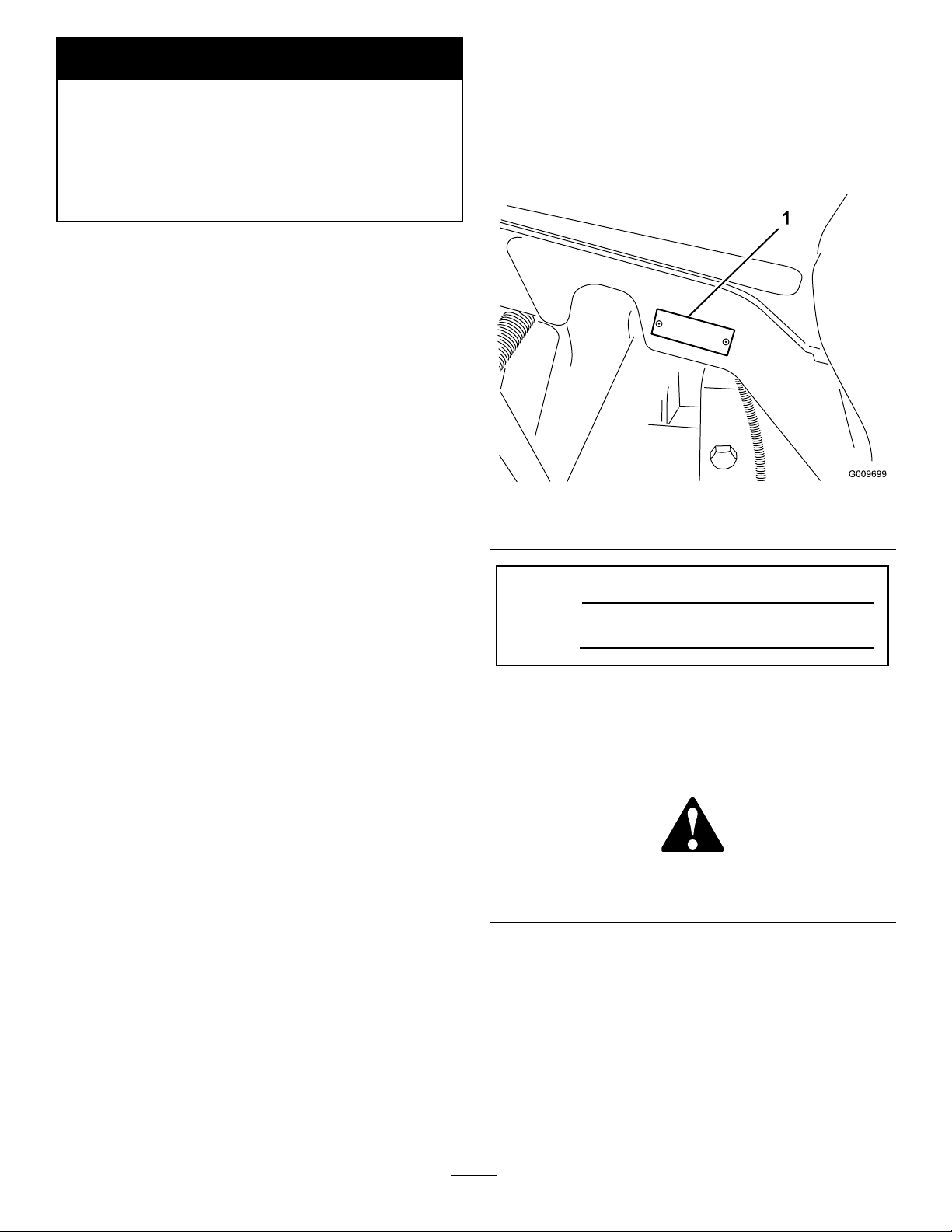
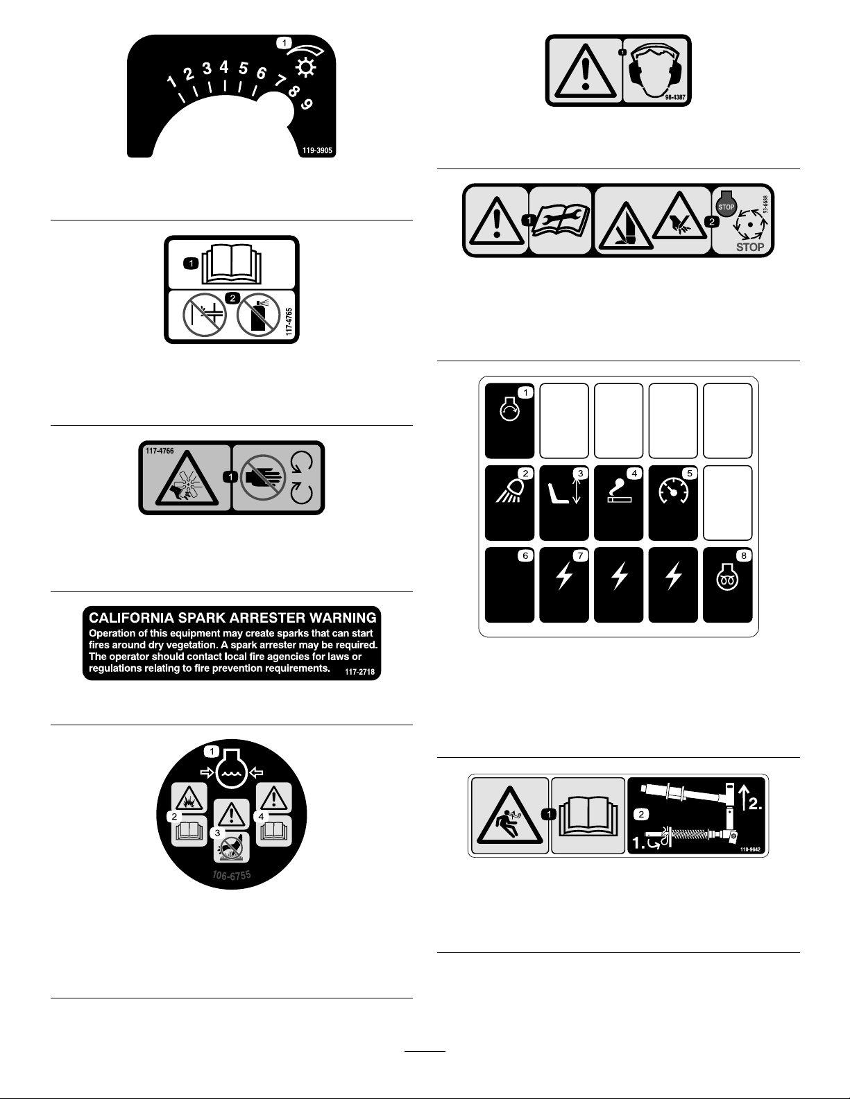
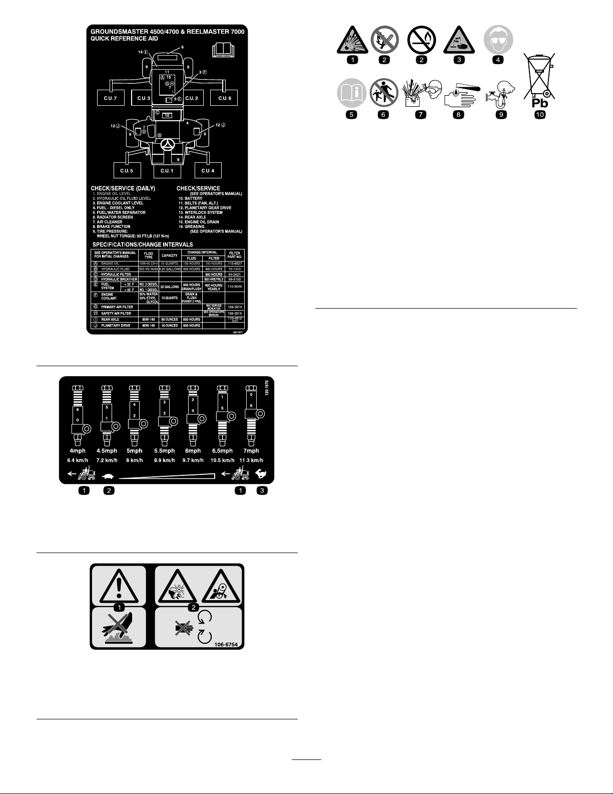
SafetyandInstructionalDecals.............................7
Setup.........................................................................11
1AdjustingtheSupportRollers...........................12
2InstallingtheCuttingUnits..............................12
3AdjustingtheTurfCompensation
Spring............................................................15
4UsingtheCuttingUnitKickstand.....................16
5GreasingtheMachine......................................16
6CheckingFluidLevels......................................17
ProductOverview......................................................17
Controls.............................................................17
Specications.....................................................21
TractionUnitSpecications................................21
Attachments/Accessories...................................21
Operation...................................................................22
CheckingtheEngineOilLevel............................22
CheckingtheCoolingSystem..............................23
FillingtheFuelTank...........................................23
CheckingtheHydraulicFluidLevel.....................25
CheckingtheTirePressure.................................26
StartingandStoppingtheEngine........................26
CheckingtheInterlockSwitches.........................26
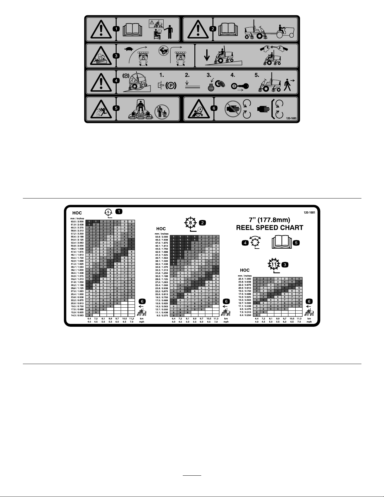
SettingtheReelSpeed.........................................27
AdjustingtheLiftArmCounterbalance...............28
AdjustingtheLiftArmTurnAround
Position..........................................................28
PushingorTowingtheMachine..........................29
JackingPoints.....................................................29
TieDowns.........................................................29
UnderstandingtheDiagnosticLight....................29
DiagnosticAceDisplay.......................................30
CheckingtheInterlockSwitches.........................30
OperatingCharacteristics...................................31
EngineCoolingFanOperation...........................32
OperatingTips...................................................32
Maintenance...............................................................33
RecommendedMaintenanceSchedule(s)................33
DailyMaintenanceChecklist...............................34
ServiceIntervalChart.........................................35
PremaintenanceProcedures....................................36
RemovingtheHood...........................................36
Lubrication.............................................................36
GreasingtheBearingsandBushings....................36
EngineMaintenance...............................................38
ServicingtheAirCleaner....................................38
ServicingtheEngineOilandFilter......................39
AdjustingtheThrottle........................................39
FuelSystemMaintenance.......................................40
FuelTank...........................................................40
FuelLinesandConnections................................40
ServicingtheWaterSeparator.............................40
FuelPickupTubeScreen....................................40
BleedingAirfromtheInjectors...........................41
ElectricalSystemMaintenance................................41
ChargingandConnectingtheBattery..................41
BatteryCare.......................................................42
Fuses..................................................................43
DriveSystemMaintenance.....................................44
CheckingtheTorqueoftheWheel
Nuts...............................................................44
CheckingthePlanetaryGearDrive
Oil..................................................................44
ChangingthePlanetaryGearDrive
Oil..................................................................44
CheckingtheRearAxleLubricant.......................45
ChangingtheRearAxleLubricant.......................45
AdjustingtheTractionDriveforNeutral.............46
CheckingtheRearWheelToe-In.........................46
CoolingSystemMaintenance..................................47
ServicingtheEngineCoolingSystem..................47
BrakeMaintenance.................................................48
AdjustingtheServiceBrakes...............................48
BeltMaintenance....................................................48
ServicingtheAlternatorBelt...............................48
HydraulicSystemMaintenance...............................49
ChangingtheHydraulicFluid.............................49
ReplacingtheHydraulicFilters...........................49
CheckingtheHydraulicLinesandHoses.............50
CuttingUnitMaintenance.......................................50
BacklappingtheCuttingUnits............................50
Cleaning.................................................................51
ServicingtheSparkArrestorMufer...................51
Storage.......................................................................52
Engine...............................................................52
TractionUnit......................................................52
Schematics.................................................................53
3

Safety
ThismachinemeetsorexceedsANSIB71.4-2004
specicationsineffectatthetimeofproduction.
Improperuseormaintenancebytheoperatoror
ownercanresultininjury.Toreducethepotential
forinjury,complywiththesesafetyinstructions
andalwayspayattentiontothesafetyalertsymbol,
whichmeansCAUTION,WARNING,orDANGER-
"personalsafetyinstruction."Failuretocomplywiththe
instructionmayresultinpersonalinjuryordeath.
SafeOperatingPractices
ThefollowinginstructionsarefromtheCENstandard
EN836:1997,ISOstandard5395:1990,andANSI
B71.4-2004.
Training
•Readtheoperator'smanualandothertraining
materialcarefully.Befamiliarwiththecontrols,
safetysigns,andtheproperuseoftheequipment.
•Neverallowchildrenorpeopleunfamiliarwiththese
instructionstouseorservicethemower.Local
regulationsmayrestricttheageoftheoperator.
•Nevermowwhilepeople,especiallychildren,orpets
arenearby.
•Keepinmindthattheoperatororuserisresponsible
foraccidentsorhazardsoccurringtootherpeopleor
theirproperty.
•Donotcarrypassengers.
•Alldriversandmechanicsshouldseekandobtain
professionalandpracticalinstruction.Theowneris
responsiblefortrainingtheusers.Suchinstruction
shouldemphasize:
–theneedforcareandconcentrationwhen
workingwithride-onmachines;
–controlofaride-onmachineslidingonaslope
willnotberegainedbytheapplicationofthe
brake.Themainreasonsforlossofcontrolare:
◊insufcientwheelgrip;
◊beingdriventoofast;
◊inadequatebraking;
◊thetypeofmachineisunsuitableforitstask;
◊lackofawarenessoftheeffectofground
conditions,especiallyslopes;
◊incorrecthitchingandloaddistribution.
•Theowner/usercanpreventandisresponsiblefor
accidentsorinjuriesoccurringtohimselforherself,
otherpeople,orproperty.
Preparation
•Whilemowing,alwayswearsubstantialfootwear,
longtrousers,hardhat,safetyglasses,andear
protection.Longhair,looseclothing,orjewelrymay
gettangledinmovingparts.Donotoperatethe
equipmentwhenbarefootorwearingopensandals.
•Thoroughlyinspecttheareawheretheequipment
istobeusedandremoveallobjectswhichmaybe
thrownbythemachine.
•Warning—Fuelishighlyammable.Takethe
followingprecautions:
–Storefuelincontainersspecicallydesignedfor
thispurpose.
–Refueloutdoorsonlyanddonotsmokewhile
refuelling.
–Addfuelbeforestartingtheengine.Never
removethecapofthefueltankoraddfuelwhile
theengineisrunningorwhentheengineishot.
–Iffuelisspilled,donotattempttostartthe
enginebutmovethemachineawayfromthe
areaofspillageandavoidcreatinganysourceof
ignitionuntilfuelvaporshavedissipated.
–Replaceallfueltanksandcontainercapssecurely.
•Replacefaultysilencers/mufers.
•Evaluatetheterraintodeterminewhataccessories
andattachmentsareneededtoproperlyand
safelyperformthejob.Onlyuseaccessoriesand
attachmentsapprovedbythemanufacturer.
•Checkthattheoperator'spresencecontrols,safety
switchesandshieldsareattachedandfunctioning
properly.Donotoperateunlesstheyarefunctioning
properly.
Operation
•Donotoperatetheengineinaconnedspacewhere
dangerouscarbonmonoxidefumescancollect.
•Mowonlyindaylightoringoodarticiallight.
•Beforeattemptingtostarttheengine,disengageall
bladeattachmentclutches,shiftintoneutral,and
engagetheparkingbrake.
•Rememberthereisnosuchthingasasafeslope.
Travelongrassslopesrequiresparticularcare.To
guardagainstoverturning:
–donotstoporstartsuddenlywhengoingupor
downhill;
–machinespeedsshouldbekeptlowonslopes
andduringtightturns;
–stayalertforhumpsandhollowsandother
hiddenhazards;
4

–Donotturnsharply.Usecarewhenreversing.
–Usecounterweight(s)orwheelweightswhen
suggestedintheoperator'smanual.
•Stayalertforholesintheterrainandotherhidden
hazards.
•Watchoutfortrafcwhencrossingornearroadways.
•Stopthebladesrotatingbeforecrossingsurfaces
otherthangrass.
•Whenusinganyattachments,neverdirectdischarge
ofmaterialtowardbystandersnorallowanyonenear
themachinewhileinoperation.
•Neveroperatethemachinewithdamagedguards,
shields,orwithoutsafetyprotectivedevicesinplace.
Besureallinterlocksareattached,adjustedproperly,
andfunctioningproperly.
•Donotchangetheenginegovernorsettingsor
over-speedtheengine.Operatingtheengineat
excessivespeedmayincreasethehazardofpersonal
injury.
•Beforeleavingtheoperator'sposition:
–stoponlevelground;
–disengagethepowertake-offandlowerthe
attachments;
–changeintoneutralandsettheparkingbrake;
–stoptheengineandremovethekey.
•Disengagedrivetoattachmentswhentransporting
ornotinuse.
•Stoptheengineanddisengagedrivetoattachment:
–beforerefuelling;
–beforemakingheightadjustmentunless
adjustmentcanbemadefromtheoperator's
position.
–beforeclearingblockages;
–beforechecking,cleaningorworkingonthe
mower;
–afterstrikingaforeignobjectorifanabnormal
vibrationoccurs.Inspectthemowerfordamage
andmakerepairsbeforerestartingandoperating
theequipment.
•Reducethethrottlesettingduringenginerun-out
and,iftheengineisprovidedwithashut-offvalve,
turnthefueloffattheconclusionofmowing.
•Keephandsandfeetawayfromthecuttingunits.
•Lookbehindanddownbeforebackinguptobesure
ofaclearpath.
•Slowdownandusecautionwhenmakingturnsand
crossingroadsandsidewalks.Stopcylinders/reels
ifnotmowing.
•Donotoperatethemowerundertheinuenceof
alcoholordrugs.
•Lightningcancausesevereinjuryordeath.If
lightningisseenorthunderisheardinthearea,do
notoperatethemachine;seekshelter.
•Usecarewhenloadingorunloadingthemachine
intoatrailerortruck.
•Usecarewhenapproachingblindcorners,shrubs,
trees,orotherobjectsthatmayobscurevision.
MaintenanceandStorage
•Keepallnuts,boltsandscrewstighttobesurethe
equipmentisinsafeworkingcondition.
•Neverstoretheequipmentwithfuelinthetank
insideabuildingwherefumesmayreachanopen
ameorspark.
•Allowtheenginetocoolbeforestoringinany
enclosure.
•Toreducetherehazard,keeptheengine,
silencer/mufer,batterycompartmentandfuel
storageareafreeofgrass,leaves,orexcessivegrease.
•Keepallpartsingoodworkingconditionandall
hardwareandhydraulicttingstightened.Replaceall
wornordamagedpartsanddecals.
•Ifthefueltankhastobedrained,dothisoutdoors.
•Becarefulduringadjustmentofthemachineto
prevententrapmentofthengersbetweenmoving
bladesandxedpartsofthemachine.
•Onmulti-cylinder/multi-reelmachines,takecare
asrotatingonecylinder/reelcancauseother
cylinders/reelstorotate.
•Disengagedrives,lowerthecuttingunits,setparking
brake,stopengineandremovekeyfromignition.
Waitforallmovementtostopbeforeadjusting,
cleaningorrepairing.
•Cleangrassanddebrisfromcuttingunits,drives,
silencers/mufers,andenginetohelppreventres.
Cleanupoilorfuelspillage.
•Usejackstandstosupportcomponentswhen
required.
•Carefullyreleasepressurefromcomponentswith
storedenergy.
•Disconnectbatterybeforemakinganyrepairs.
Disconnectthenegativeterminalrstandthe
positivelast.Reconnectpositiverstandnegative
last.
•Usecarewhencheckingthecylinders/reels.Wear
glovesandusecautionwhenservicingthem.
5

•Keephandsandfeetawayfrommovingparts.If
possible,donotmakeadjustmentswiththeengine
running.
•Chargebatteriesinanopenwellventilatedarea,
awayfromsparkandames.Unplugchargerbefore
connectingordisconnectingfrombattery.Wear
protectiveclothinganduseinsulatedtools.
ToroRidingMowerSafety
Thefollowinglistcontainssafetyinformationspecic
toToroproductsorothersafetyinformationthatyou
mustknowthatisnotincludedintheCEN,ISO,or
ANSIstandard.
Thisproductiscapableofamputatinghandsand
feetandthrowingobjects.Alwaysfollowallsafety
instructionstoavoidseriousinjuryordeath.
Useofthisproductforpurposesotherthanitsintended
usecouldprovedangeroustouserandbystanders.
WARNING
Engineexhaustcontainscarbonmonoxide,which
isanodorless,deadlypoisonthatcankillyou.
Donotrunengineindoorsorinanenclosedarea.
•Knowhowtostoptheenginequickly.
•Donotoperatethemachinewhilewearingtennis
shoesorsneakers.
•Wearingsafetyshoesandlongpantsisadvisableand
requiredbysomelocalordinancesandinsurance
regulations.
•Handlefuelcarefully.Wipeupanyspills.
•Checkthesafetyinterlockswitchesdailyforproper
operation.Ifaswitchshouldfail,replacetheswitch
beforeoperatingthemachine.
•Beforestartingtheengine,sitontheseat.
•Usingthemachinedemandsattention.Toprevent
lossofcontrol:
–Donotdriveclosetosandtraps,ditches,creeks,
embankments,orotherhazards.
–Reducespeedwhenmakingsharpturns.Avoid
suddenstopsandstarts.
–Whennearorcrossingroads,alwaysyieldthe
right-of-way.
–Applytheservicebrakeswhengoingdownhillto
keepforwardspeedslowandtomaintaincontrol
ofthemachine.
•WhenoperatingamachinewithROPS(roll-over
protectionsystem)neverremovetheROPSand
alwaysusetheseatbelt.
•Raisethecuttingunitswhendrivingfromonework
areatoanother.
•Donottouchtheengine,silencer/mufer,or
exhaustpipewhiletheengineisrunningorsoon
afterithasstoppedbecausetheseareascouldbehot
enoughtocauseburns.
•Onanyhill,thereisthepossibilityoftippingor
rollingover,buttheriskincreasesastheslopeangle
increases.Steephillsshouldbeavoided.
Cuttingunitsmustbeloweredwhengoingdown
slopestomaintainsteeringcontrol
•Engagetractiondriveslowly,alwayskeepfooton
tractionpedal,especiallywhentravelingdownhill.
Usereverseontractionpedalforbraking.
•Ifthemachinestallswhenclimbingaslope,do
notturnthemachinearound.Alwaysbackslowly,
straightdowntheslope.
•Whenapersonorpetappearsunexpectedlyin
ornearthemowingarea,stopmowing.Careless
operation,combinedwithterrainangles,ricochets,
orimproperlypositionedguardscanleadtothrown
objectinjuries.Donotresumemowinguntilthe
areaiscleared.
MaintenanceandStorage
•Makesureallhydrauliclineconnectorsaretightand
allhydraulichosesandlinesareingoodcondition
beforeapplyingpressuretothesystem.
•Keepyourbodyandhandsawayfrompinhole
leaksornozzlesthatejecthydraulicuidunder
highpressure.Usepaperorcardboard,notyour
hands,tosearchforleaks.Hydraulicuidescaping
underpressurecanhavesufcientforcetopenetrate
theskinandcauseseriousinjury.Seekimmediate
medicalattentionifuidisinjectedintoskin.
•Beforedisconnectingorperforminganyworkon
thehydraulicsystem,allpressureinthesystemmust
berelievedbystoppingtheengineandloweringthe
cuttingunitsandattachmentstotheground.
•Checkallfuellinesfortightnessandwearona
regularbasis.Tightenorrepairthemasneeded.
•Iftheenginemustberunningtoperforma
maintenanceadjustment,keephands,feet,clothing,
andanypartsofthebodyawayfromthecutting
units,attachments,andanymovingparts.
•Toensuresafetyandaccuracy,haveanAuthorized
ToroDistributorcheckthemaximumenginespeed
withatachometer.
6

•Ifmajorrepairsareeverneededorifassistanceis
desired,contactanAuthorizedToroDistributor.
•UseonlyToro-approvedattachmentsand
replacementparts.Thewarrantymaybevoidedif
usedwithunapprovedattachments.
SafetyandInstructionalDecals
Safetydecalsandinstructionsareeasilyvisibletotheoperatorandarelocatednearanyareaof
potentialdanger.Replaceanydecalthatisdamagedorlost.
117-4763
1.Toengagetheparking
brake,securethebrake
pedalswiththelockingpin,
presstheparkingbrake
pedalsandengagethetoe
pedal.
2.Todisengagetheparking
brake,disengagethe
lockingpinandreleasethe
pedals.
117-2386
1.Raisedeck3.Reverse
2.Blowofffan4.Automatic
119-3884
1.Off4.Fast,throttle
2.Headlights5.Slow,throttle
3.On6.PowerT ake-off(PTO)
117–2385
1.ReadtheOperators
Manual.
3.Engine—preheat
2.Engine—start4.Engine—stop
7

119-3905
1.Reelspeed
117-4765
1.ReadtheOperator'sManual.
2.Donotusestartingaids.
117-4766
1.Cutting/dismembermenthazard;fan—stayawayfrom
movingparts.
117–2718
106-6755
1.Enginecoolantunder
pressure.
3.Warning—donottouchthe
hotsurface.
2.Explosionhazard—read
theOperator'sManual.
4.Warning—readthe
Operator'sManual.
98-4387
1.Warning—wearhearingprotection.
93-6688
1.Warning—readthe
instructionsbefore
servicingorperforming
maintenance.
2.Cuttinghazardofhandor
foot—stoptheengineand
waitformovingpartsto
stop.
120-1672
10A
20A
10A 10A 10A
2A 7.5A 7.5A 7.5A
TEC-5002
60A
120-1672
1.Starter,20A5.Gauges,10A
2.Worklight,10A6.GM4500controller,2A
3.Seat,10A7.Powersupplied,7.5A
4.Powerpoint,10A8.Enginepreheat,60A
110-9642
1.Storedenergyhazard—readtheOperator'sManual.
2.Movethecotterpintotheholeclosesttotherodbracket
andthenremovetheliftarmandpivotyoke.
8

120-1683
1.Warning—readtheOperator'sManual,donotoperatethis
machineunlessyouaretrained.
4.Warning—donotparkthemachineonslopes;engagethe
parkingbrake,lowerthecuttingunits,stoptheengineand
removetheignitionkeybeforeleavingthemachine.
2.Warning—readtheOperator'sManualbeforetowingthe
machine.
5.Thrownobjecthazard—keepbystandersasafedistancefrom
themachine.
3.Tippinghazard—slowmachinebeforeturning,donotturnat
highspeeds;lowerthecuttingunitwhendrivingdownslopes;
usearolloverprotectionsystemandweartheseatbelt
6.Entanglementhazard,belt—stayawayfrommovingparts,
keepallguardsandshieldsinplace.
120-1681
1.5Bladecuttingunit3.11Bladecuttingunit5.ReadtheOperator'sManual.
2.8Bladecuttingunit4.Mowandbacklap6.Machinespeed
9

120-1671
120-1670
1.Tractionunitspeed3.Fast
2.Slow
106-6754
1.Warning—donottouchthehotsurface.
2.Cutting/dismembermenthazard,fanandentanglement
hazard,belt—stayawayfrommovingparts.
BatterySymbols
Someorallofthesesymbolsareonyourbattery
1.Explosionhazard6.Keepbystandersasafe
distancefromthebattery.
2.Nore,opename,or
smoking.
7.Weareyeprotection;
explosivegasescan
causeblindnessandother
injuries
3.Causticliquid/chemical
burnhazard
8.Batteryacidcancause
blindnessorsevereburns.
4.Weareyeprotection9.Flusheyesimmediately
withwaterandgetmedical
helpfast.
5.ReadtheOperator's
Manual.
10.Containslead;donot
discard.
10

Setup
LooseParts
Usethechartbelowtoverifythatallpartshavebeenshipped.
ProcedureDescriptionQty.Use
1Nopartsrequired–Adjustthesupportrollers
Fronthoseguide-R.H.1
2Fronthoseguide-L.H.1Installthecuttingunits
3Nopartsrequired–Adjusttheturfcompensationspring.
4Cuttingunitkickstand1InstalltheCuttingUnitKickstand.
5Nopartsrequired–Greasethemachine.
6Nopartsrequired–Checktherearaxlelubricant,hydraulic
uid,andengineoillevels
MediaandAdditionalParts
DescriptionQty.Use
Operator'sManual1Readbeforeoperatingmachine
EngineOperator'sManual1Readbeforeoperatingengine
PartsCatalog1Usetoreferencepartnumbers
OperatorTrainingMaterial1Viewbeforeoperatingmachine
Note:Determinetheleftandrightsidesofthemachinefromthenormaloperatingposition.
11

1
AdjustingtheSupportRollers
NoPartsRequired
Procedure
Dependingonwhatwidthcuttingunitsaretobeinstalled
onthetraction,adjustthesupportrollersasfollows:
•Ifusing27inchcuttingunits,therollersaretobe
installedintheuppermountingholesofsupport
assemblychannels(Figure3).
•Ifusing32inchcuttingunits,therollersaretobe
installedinthelowermountingholesofsupport
assemblychannels(Figure3).
g019541
1
2
3
Figure3
1.Supportassemblychannel3.Usethisholefor32inch
cuttingunits
2.Usethisholefor27inch
cuttingunits
2
InstallingtheCuttingUnits
Partsneededforthisprocedure:
1Fronthoseguide-R.H.
1Fronthoseguide-L.H.
Procedure
1.Removethereelmotorsfromtheshippingbrackets.
2.Removetheshippingbracketsanddiscard.
3.Removethecuttingunitsfromthecartons.Assemble
andadjustasdescribedinthecuttingunitOperator's
Manual.
4.Makesurethecounterweight(Figure4)isinstalled
totheproperendofthecuttingunitasdescribedin
thecuttingunitOperator'sManual.
Figure4
1.Counterweight
5.Allthecuttingunitsareshippedwiththeturf
compensationspringmountedtotherightsideofthe
cuttingunit.Theturfcompensationspringmustbe
mountedtothesamesideofthecuttingunitasthe
reeldrivemotor.Repositiontheturfcompensation
asfollows:
A.Removethe2carriageboltsandnutssecuring
therodbrackettothecuttingunittabs(Figure5).
Figure5
1.Turfcompensationspring3.Springtube
2.Rodbracket
B.Removetheangenutsecuringthespringtube
bolttothecarrierframetab(Figure5)Remove
theassembly.
C.Mountthespringtubebolttotheoppositetab
onthecarrierframeandsecurewiththeange
12

nut.Theboltheadistobepositionedtothe
outersideofthetabasshowninFigure6.
Figure6
1.Oppositecarrierframetab2.Rodbracket
D.Mounttherodbrackettothecuttingunittabs
withthecarriageboltsandnuts(Figure6).Also,
onthecuttingunit,mountthelefthandhose
guidetothefrontofthecuttingunittabswhen
reinstallingtherodbracket(Figure8).
Important:Onthe#4(leftfront)and#5
(rightfront)cuttingunits,usetherodbracket
mountingnutstoinstallthehoseguidesto
thefrontofthecuttingunittabs.Thehose
guidesshouldleantowardthecentercutting
unit(Figure7throughFigure9).
Figure7
Figure8
1.Hoseguide(Lefthand
shown)
3.Nuts
2.Rodbracket
g019602
11
Figure9
1.Hoseguides(eachmustleantowardthecentercuttingunit)
Note:Wheninstallingorremovingthecutting
units,makesurethehairpincotterisinstalled
inthespringrodholenexttotherodbracket.
Otherwise,thehairpincottermustbeinstalledin
theholeintheendoftherod.
6.On27inchcuttingunitsonly,increasethesteering
ontherearcuttingunitsbyremovingthe(2)pivot
spacers,hexsocketscrewsandangelocknuts
(Figure10)fromtherear(#2and#3)cuttingunit
carrierframes(Figure7).
13

Note:32inchcuttingunitsarenotequippedwith
pivotspacers.
1
2
3
4
G015978
Figure10
1.Hexsocketscrew3.Carrierframe
2.Pivotspacer4.Flangelocknut
7.Loweralltheliftarmscompletely.
8.Coatthecarrierframeshaftwithcleangrease
(Figure11).
9.Forthefrontcuttingunits,slideacuttingunitunder
theliftarmwhileinsertingthecarrierframeshaftup
intotheliftarmpivotyoke(Figure11).Makesure
thethrustwasherisinpositiononthecarrierframe
shaft.
10.Securethecarrierframeshafttotheliftarmyoke
withtheKlikpin(Figure11).
G015976
1
2
3
4
5
Figure11
1.Liftarmpivotyoke4.Carrierframeshaft
2.Liftarm5.Thrustwasher
3.Klikpin
11.Tolock(x)thesteeringonthecuttingunits,secure
thepivotyoketothecarrierframewiththesnapper
pin(Figure12).
1
G015977
Figure12
1.Snapperpin
Note:Fixedsteeringisrecommendedwhen
cuttingsidehills.
12.Usethefollowingprocedureontherearcuttingunits
whentheheightofcutisabove3/4inch.
14

A.Removethelynchpinandwashersecuringthe
liftarmpivotshafttotheliftarmandslidethe
liftarmpivotshaftoutoftheliftarm(Figure13).
Figure13
1.Liftarmpivotshaftlynchpinandwasher
B.Inserttheliftarmyokeontothecarrierframe
shaft(Figure11).
C.Inserttheliftarmshaftintotheliftarm
andsecureitwiththewasherandlynchpin
(Figure13).
13.Securetheliftarmchaintothechainbracketwith
thesnapperpin(Figure14).Usethenumberofchain
linksdescribedinthecuttingunitOperator'sManual.
Figure14
1.Liftarmchain3.Snapperpin
2.Chainbracket
14.Coatthesplineshaftofthereelmotorwithclean
grease.
15.OilthereelmotorO-ringandinstallitontothe
motorange.
16.Installthemotorbyrotatingitclockwisesothatthe
motorangesclearthebolts(Figure15).Rotatethe
motorcounterclockwiseuntiltheangesencirclethe
boltsthentightenthebolts.
Important:Makesurethereelmotorhoses
arenottwisted,kinkedorintheriskofbeing
pinched.
Figure15
1.Reeldrivemotor2.Mountingbolts
3
AdjustingtheTurf
CompensationSpring
NoPartsRequired
Procedure
Theturfcompensationspring(Figure16)transfers
weightfromthefronttotherearroller.(Thishelps
toreduceawavepatternintheturf,alsoknownas
marcellingorbobbing.)
Important:Makespringadjustmentswiththe
cuttingunitmountedtothetractionunit,pointing
straightaheadandloweredtotheshopoor.
1.Makesurethehairpincotterisinstalledintherear
holeinthespringrod(Figure16).
Note:Whenservicingthecuttingunit,movethe
hairpincottertothespringrodholenexttotheturf
compensationspring.
15

Figure16
1.Turfcompensationspring3.Springrod
2.Hairpincotter4.Hexnuts
2.Tightenthehexnutsonthefrontendofthespring
roduntilthecompressedlengthofthespringis6.25
inches(15.9cm)(Figure16).
Note:Whenoperatingonroughterraindecrease
thespringlengthby1/2inch.Groundfollowingwill
beslightlydecreased.
Note:Theturfcompensationsettingwillneedto
beresetiftheHOCsettingortheAggressiveness
ofCutsettingischanged.
4
UsingtheCuttingUnit
Kickstand
Partsneededforthisprocedure:
1Cuttingunitkickstand
Procedure
Wheneverthecuttingunithastobetippedtoexpose
thebedknife/reel,propuptherearofthecuttingunit
withthekickstandtomakesurethenutsontheback
endofthebedbaradjustingscrewsarenotrestingonthe
worksurface(Figure17).
Figure17
1.Cuttingunitkickstand
Securethekickstandtothechainbracketwiththe
snapperpin(Figure18).
Figure18
1.Chainbracket3.Cuttingunitkickstand
2.Snapperpin
16

5
GreasingtheMachine
NoPartsRequired
Procedure
Beforethemachineisoperated,itmustbegreasedto
ensureproperlubrication.RefertoLubricationsection.
Failuretoproperlygreasethemachinewillresultin
prematurefailureofcriticalparts.
6
CheckingFluidLevels
NoPartsRequired
Procedure
1.Checktherearaxlelubricantlevelbeforetheengine
isrststarted,refertoCheckingtheRearAxle
LubricantinDriveSystemMaintenance.
2.Checkthehydraulicuidlevelbeforetheengineis
rststarted,refertoCheckingtheHydraulicFluid
LevelinOperation.
3.Checktheengineoillevelbeforeandaftertheengine
isrststarted,refertoCheckingtheEngineOil
LevelinOperation.
ProductOverview
Controls
BrakePedals
Twofootpedals(Figure19)operateindividualwheel
brakesforturningassistanceandtoaidinobtaining
bettersidehilltraction.
PedalLockingLatch
Thepedallockinglatch(Figure19)connectsthepedals
togethertoengagetheparkingbrake.
ParkingBrakePedal
Toengagetheparkingbrake,(Figure19)connectthe
pedalstogetherwiththepedallockinglatch,pushdown
ontherightbrakepedalwhileengagingthetoepedal.To
releasetheparkingbrake,pressoneofthebrakepedals
untiltheparkingbrakelatchretracts.
Figure19
1.Brakepedal4.Tractionpedal
2.Pedallockinglatch5.Tiltsteeringpedal
3.Parkingbrakepedal
TractionPedal
Thetractionpedal(Figure19)controlsforwardand
reverseoperation.Depressthetopofthepedaltomove
forwardandthebottomtomovebackward.Ground
speeddependsonhowfarthepedalisdepressed.For
noload,maximumgroundspeed,fullydepressthepedal
whilethethrottleisinFast.
Tostop,reduceyourfootpressureonthetractionpedal
andallowittoreturntothecenterposition.
TiltSteeringPedal
Totiltthesteeringwheeltowardsyou,pressthefoot
pedal(Figure19)down,andpullthesteeringtower
17

towardyoutothemostcomfortablepositionandthen
releasethepedal.
MowSpeedLimiter
Whenthemowspeedlimiter(Figure20)isippedupit
willcontrolthemowspeedandallowthecuttingunits
tobeengaged.Eachspaceradjuststhemowingspeed
by½mileperhour.Themorespacersyouhave,onthe
topoftheboltthesloweryouwillgo.Fortransport,ip
backthemowspeedlimiterandyouwillhavemaximum
transportspeed.
SpeedLimiterScrews
Adjustthescrew(s)(Figure20)tolimittheamountthe
tractionpedalcanbedepressedintheforwardorreverse
directiontolimitspeed.
Important:Thespeedlimiterscrewmuststopthe
tractionpedalbeforethepumpreachesfullstroke
ordamagetothepumpmayoccur.
Figure20
1.Reversespeedlimiter
screw
3.Spacers
2.Forwardspeedlimiter
screw
4.Mowspeedlimiter
DiagnosticLight
Thediagnosticlight(Figure21)willilluminateshoulda
systemfaultberecognized.
EngineCoolantTemperatureGauge
Duringnormaloperatingconditionsthegauge
(Figure21)shouldbeinthegreenrange.Checkthe
coolingsystemifthegaugegoestotheyelloworred
range.
EngineOilPressureWarningLight
Thelight(Figure21)illuminateswhentheengineoil
pressureisdangerouslylow .
ChargeIndicator
Thechargeindicator(Figure21)illuminateswhenthe
systemchargingcircuitmalfunctions.
KeySwitch
Thekeyswitch(Figure21)hasthreepositions:Off,
On/Preheat,andStart.
PTOSwitch
ThePTOswitch(Figure21)hastwopositions:Out
(start)andIn(stop).PullthePTObuttonouttoengage
thecuttingunitblades.Pushinthebuttontodisengage
thecuttingunitblades.
Figure21
1.Diagnosticlight7.Liftswitch
2.Enginecoolant
temperaturegauge
8.Throttlecontrol
3.Engineoilpressure
warninglight
9.Lightswitch
4.Chargeindicator10.Glowplugindicatorlight
5.Keyswitch11.Enginecoolant
temperaturewarning
light
6.PTOswitch
LiftSwitch
Theliftswitch(Figure21)raisesandlowersthecutting
units.Presstheswitchforwardtolowerthecuttingunits
andbackwardtoraisethecuttingunits.Whenstarting
18

themachine,withthecuttingunitsinthedownposition,
presstheliftswitchdowntoallowthecuttingunitsto
oatandmow .
ThrottleControl
Movethecontrol(Figure21)forwardtoincreasethe
enginespeedandrearwardtodecreasethespeed.
LightSwitch
Presstheloweredgeoftheswitch(Figure21)toturnon
thelights.Presstheupperedgeoftheswitchtoturn
offthelights.
GlowPlugIndicatorLight
Whenlit,theglowplugindicatorlight(Figure21)
indicatesthattheglowplugsareon.
EngineCoolantTemperatureWarning
Light
Thelight(Figure21)illuminatesandthecuttingunits
shutdown(PTOdisengages).Ifthetemperature
continuestorisetheenginewillshutdown.
PowerPoint
Thepowerpoint(Figure22)isusedtopoweroptional
12voltelectricalaccessories.
Figure22
1.Powerpoint3.Bagholder
2.Enginecoolingfanswitch4.Hourmeter
EngineCoolingFanSwitch
Themachineisequippedwithahydraulicallydrivenauto
reversingenginecoolingfan.Thefanswitch(Figure22)
hastwopositionsR(manualreverse)andAuto(normal).
RefertoEngineCoolingFanOperationintheOperation
Sectionofmanual.
BagHolder
Usethebagholder(Figure22)forstorage.
HourMeter
Thehourmeter(Figure22)showsthetotalhoursthat
themachinehasbeenoperated.
BacklapLevers
Usethebacklapleversforbacklappingthereels
(Figure23).
Figure23
1.Frontbacklaplever2.Rearbacklaplever
ReelSpeedControl
Thereelspeedcontrolregulatesthespeedofthefront
andrearcuttingunits(Figure24).Thereelspeed
increasesastheknobisturnedclockwise.
19

Figure24
1.Reelspeedcontrols
FuelGauge
Thefuelgauge(Figure25)indicatestheleveloffuelin
thetank.
Figure25
1.Fuelgauge
SeatAdjustments
ForeandAftAdjustingLever
Pulloutonthelevertoslidetheseatforeoraft
(Figure26).
SeatArmRestAdjustingKnob
Rotatetheknobtoadjusttheseatarmrestangle
(Figure26).
SeatBackAdjustingLever
Movethelevertoadjusttheseatbackangle(Figure26).
Weightgauge
Indicateswhentheseatisadjustedtotheweightofthe
operator(Figure26).Heightadjustmentismadeby
positioningthesuspensionwithintherangeofthegreen
region.
Figure26
1.Weightgauge4.Seatbackadjustinglever
2.Weightadjustinglever5.Armrestadjustingknob
3.ForeandAftadjusting
lever
WeightAdjustingLever
Adjustforoperatorweight(Figure26).Pulluponthe
levertoincreasetheairpressureandpushdownto
decreasetheairpressure.Theproperadjustmentis
attainedwhentheweightgaugeisinthegreenregion.
20
This manual suits for next models
1
Table of contents
Other Toro Lawn Mower manuals

Toro
Toro 74301 User manual

Toro
Toro Z Master 74919TE User manual

Toro
Toro Groundsmaster 4300-D User manual

Toro
Toro TimeCutter Z5000 74391 User manual

Toro
Toro TimeCutter 6000 Series User manual

Toro
Toro ProLine 30197 User manual

Toro
Toro 4042 User manual

Toro
Toro 30853 User manual

Toro
Toro 73580 User manual

Toro
Toro 30241 Groundsmaster 228-D User manual

Toro
Toro Flex-Force Power System 21863 User manual

Toro
Toro 22189TE User manual

Toro
Toro 30074 User manual

Toro
Toro 78216 User manual

Toro
Toro Greensmaster eTriFlex 3360 User manual

Toro
Toro 8766 User manual

Toro
Toro Z Master Z597 User manual

Toro
Toro 30343 User manual

Toro
Toro TimeCutter Manual

Toro
Toro 21852 User manual