Safety
Hazardcontrolandaccidentpreventionaredependent
upontheawareness,concern,andpropertraining
ofthepersonnelinvolvedintheoperation,transport,
maintenance,andstorageofthemachine.Improper
useormaintenanceofthemachinecanresultininjury
ordeath.Toreducethepotentialforinjuryordeath,
complywiththefollowingsafetyinstructions.
•Read,understand,andfollowallinstructionsinthe
tractionunitandcuttingunitOperator’sManualsbefore
operatingthecuttingunit.
•Neverallowchildrentooperatethetractionunitor
cuttingunits.Donotallowadultstooperatetractionunit
orcuttingunitswithoutproperinstruction.Onlytrained
operatorswhohavereadthismanualshouldoperatethe
tractionunitorcuttingunits.
•Neveroperatethecuttingunitswhenundertheinuence
ofdrugsoralcohol.
•Keepallshieldsandsafetydevicesinplace.Ifashield,
safetydeviceordecalisillegibleordamaged,repairor
replaceitbeforeoperationiscommenced.Alsotighten
anyloosenuts,bolts,andscrewstoensurecuttingunitis
insafeoperatingcondition.
•Alwayswearsubstantialshoes.Donotoperatecutting
unitswhilewearingsandals,tennisshoes,sneakers,or
shorts.Also,donotwearloosettingclothingwhich
couldgetcaughtinmovingparts.Alwayswearlongpants
andsubstantialshoes.Wearingsafetyglasses,safetyshoes,
andahelmetisadvisableandrequiredbysomelocal
ordinancesandinsuranceregulations.
•Removealldebrisorotherobjectsthatmightbepicked
upandthrownbythecuttingunitreelblades.Keepall
bystandersawayfromtheworkingarea.
•Ifthecuttingbladesstrikeasolidobjectortheunit
vibratesabnormally,stopandshuttheengineoff.Check
thecuttingunitsfordamagedparts.Repairanydamage
beforerestartingandoperatingthecuttingunits.
•Lowerthecuttingunitstothegroundandremovekey
fromignitionswitchwhenevermachineisleftunattended.
•Ensurethatthecuttingunitsareinsafeoperating
conditionbykeepingnuts,bolts,andscrewstight.
•Removethekeyfromtheignitionswitchtoprevent
accidentalstartingoftheenginewhenservicing,adjusting,
orstoringthemachine.
•Performonlythosemaintenanceinstructionsdescribedin
thismanual.Ifmajorrepairsareeverneededorassistance
isdesired,contactanAuthorizedToroDistributor.
•Toensureoptimumperformanceandsafety,always
purchasegenuineTororeplacementpartsandaccessories.
Neveruse"will-t"replacementpartsand
accessoriesmadebyothermanufacturers.Lookfor
theTorologotoensuregenuineness.Usingunapproved
replacementpartsandaccessoriescouldvoidthewarranty
ofTheToroCompany.
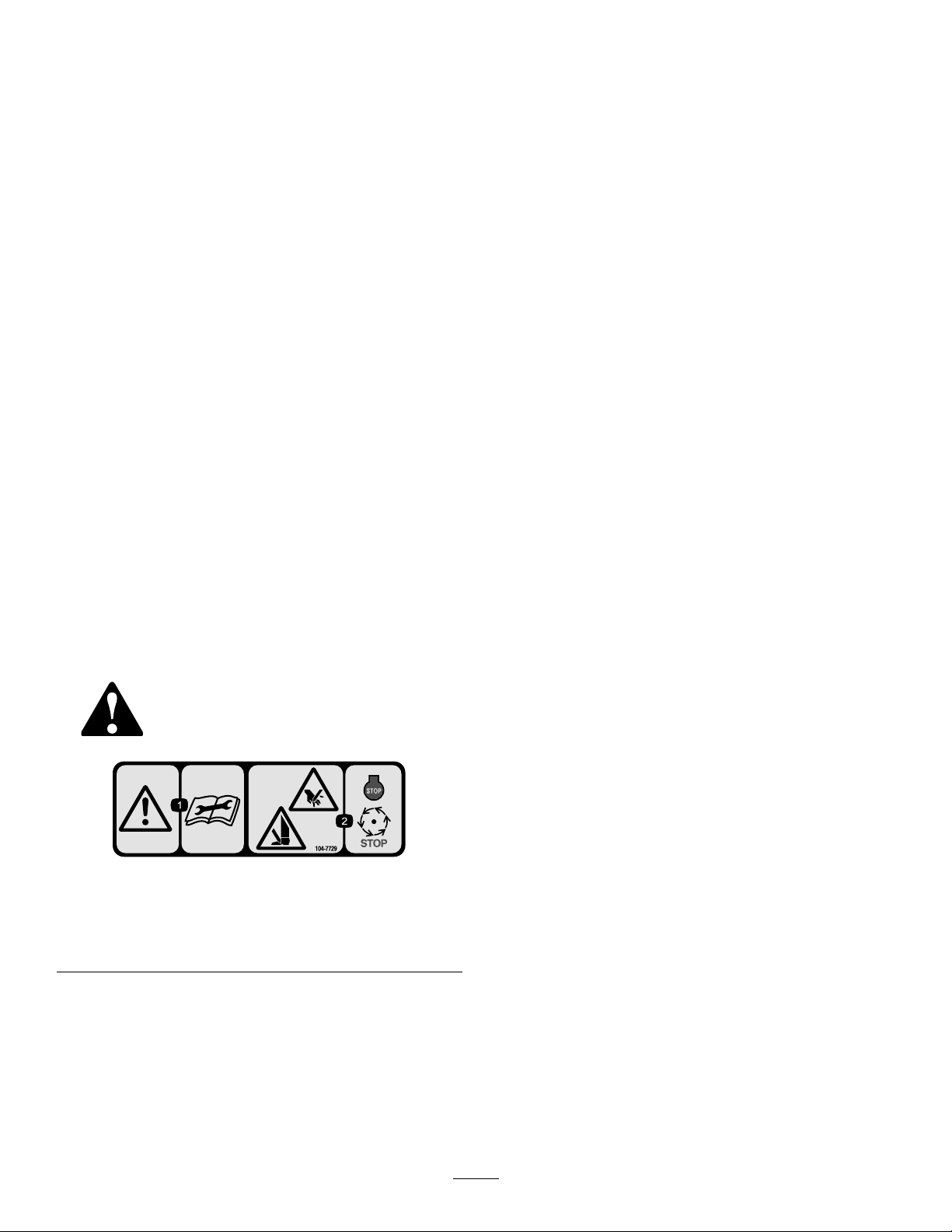
SafetyandInstructionalDecals.
Safetydecalsandinstructionsareeasilyvisibletotheoperatorandarelocatednearanyareaofpotential
danger.Replaceanydecalthatisdamagedorlost.
104–7729
1.Warning—readthe
instructionsbefore
servicingorperforming
maintenance.
2.Cutting/dismemberment
hazard;handorfoot—stop
theengineandwaitfor
movingpartstostop.
3