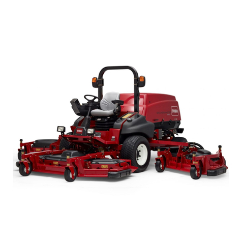
Engine:
Manufacturer—Mitsubishi.
Horsepower—22 (16 Kw) @ 3000 RPM.
Torque—40 ft-lb (54.2 Nm) @ 2400 RPM.
Displacement—58.1 cu in. (952 cc).
Crankcase Capacity—3.8 qt. (3.6 L).
Governor—Mechanical.
Governor Limit—3100–3250 RPM.
Idle Speed—1700 RPM.
Air Cleaner: Donaldson heavy duty with preclean-
er. Remote mounted.
Fuel Tank Capacit : 8.5 gal. (32 l).
Fuel Filter/Water Separator: 3-micron spin–on
type element. Replaceable (Toro Part No. 63-8300).
Fuel Pump: 12-volt electric (transistor type)
w/replaceable fuel filter (Toro Part No. 43-2550).
Cooling S stem:
Radiator—6 qt (5.7 l) capacity.
xpansion Tank—Remote mounted; 1 qt (0.946 l)
capacity. System contains a 50/50 mix of ethylene
glycol anti-freeze and water.
Electrical: Battery—12 volt, BCI group size 26, 530
Amp at 0° F. 35-amp alternator with regulator/rectifi-
er.
Drive Coupling: Transmission driven by steel shaft
with flexible rubber couplings at each end.
Transmission:
Manufacturer & Type—Sundstrand hydrostatic, Type
U15.Normal Charge Pressure – 70–150 psi
(483–1034 kPa).
Implement Relief Setting – 700–800 psi
(4 826 – 5 516 kPa).
H draulic Filter: 25-micron mounted directly to
transmission. Replaceable (Toro Part No. 23-2300).
Drive Axle: Manufacturer – Dana Corp., Model
GT–20. Axle serves as a hydraulic fluid reservoir
and mates directly with the transmission.
Approximately 5 qt (4.7 l) capacity. 4-Wheel Drive
has mechanical rear axle coupled to front axle by a
drive shaft and clutch.
Brakes: Mechanical drum type, 7 in. (17.8 cm) dia.
x 1-3/4 in. (45 mm) wide. Individually controlled by
two pedals connected by cable and conduit for steer-
ing assist. Pedals may be latched together for two
wheel braking. Lever provided for the parking
brake.
Tires, Wheels, Pressure:
Front Tires—23 x 8.50 - 12
Rear Tires—16 x 6.50 - 8
All tires 4 ply rating, tubeless type.
Pressure—20 psi (138 kPa).
Steering: 13 in. (33 cm) steering wheel. TRW power
steering valve.
Main Frame: Frame is welded, formed steel.
Instrumentation: Fuel gauge, water temperature
gauge, hour meter and warning lights for high tem-
perature shutdown, oil pressure, amperage and glow
plug are mounted on the console.
Controls: Throttle, PTO switch, parking brake,
implement lift, ignition switch and glow plug switch
are all hand-operated. Forward/reverse traction pedal
and turning brakes are foot operated.
PTO Drive: PTO shaft is clutched by a torque-
teamed HA Section, spring tensioned V-belt directly
from the engine output shaft. PTO shaft engaged by
electric clutch/brake assembly. PTO speed – 2200
RPM @ 3250 RPM engine speed.
Implement Connection—Universal joint and tele-
scoping shaft assembly.
Lift C linders: Two, with 2 in. (51 mm) bore, 3.5
in. (89 mm) stroke.
Interlock Switches: Prevents engine starting if trac-
tion pedal or PTO switch are engaged. Stops the
engine if operator leaves seat with either traction
pedal or PTO switch engaged.
Dimensions and Weight:
Length: 208 cm (82 in.)
Width (2-Wheel drive): 111 cm (44 in.)
(4-Wheel drive): 119 cm (47 in)
Height: 127 cm (50 in.)
Weight: 418 kg (1120 lb)
9
Specifications
