Toro 30834 User manual

Operator’s Manual
English (EN, GB)
Form No. 3354–410 Rev A
27,Rotary Cutting Deck
Groundsmaster)3500, 4500/4700 Traction Unit
Model No. 30834—260000001 and Up

2
All Rights Reserved
Printed in the USA
W2004 by The Toro Company
8111 Lyndale Avenue South
Bloomington, MN 55420-1196
Contents
Page
Introduction 2. . . . . . . . . . . . . . . . . . . . . . . . . . . . . . . . .
Safety 3. . . . . . . . . . . . . . . . . . . . . . . . . . . . . . . . . . . . . .
Safety and Instruction Decals 3. . . . . . . . . . . . . . . . .
Specifications 4. . . . . . . . . . . . . . . . . . . . . . . . . . . . . . . .
General Specifications 4. . . . . . . . . . . . . . . . . . . . .
Dimensions 5. . . . . . . . . . . . . . . . . . . . . . . . . . . . . . .
Optional Equipment 5. . . . . . . . . . . . . . . . . . . . . . . .
Setup 6. . . . . . . . . . . . . . . . . . . . . . . . . . . . . . . . . . . . . .
Loose Parts 6. . . . . . . . . . . . . . . . . . . . . . . . . . . . . . .
Adjusting the Carrier Frame
(Groundsmaster 3500 only) 6. . . . . . . . . . . . . . . . .
Adjusting the Height of Cut 7. . . . . . . . . . . . . . . . . .
Adjusting the Roller Scraper (Optional) 7. . . . . . . .
Installing the Mulching Baffle (Optional) 8. . . . . . .
Operation 9. . . . . . . . . . . . . . . . . . . . . . . . . . . . . . . . . . .
Operating Tips 9. . . . . . . . . . . . . . . . . . . . . . . . . . . .
Maintenance 10. . . . . . . . . . . . . . . . . . . . . . . . . . . . . . . . .
Greasing the Bearings 10. . . . . . . . . . . . . . . . . . . . . .
Cutting Deck Service Latch
(Groundsmaster 3500 only) 11. . . . . . . . . . . . . . . . .
Separating Cutting Decks from Traction Unit 11. . . .
Mounting Cutting Decks to Traction Unit 11. . . . . . .
Blade Plane 12. . . . . . . . . . . . . . . . . . . . . . . . . . . . . . .
Inspecting the Blade Plane 12. . . . . . . . . . . . . . . . . . .
Adjusting the Blade Plane 12. . . . . . . . . . . . . . . . . . .
Removing the Cutter Blade 13. . . . . . . . . . . . . . . . . .
Inspecting and Sharpening the Blade 13. . . . . . . . . . .
Blade Stopping Time 14. . . . . . . . . . . . . . . . . . . . . . .
Servicing the Front Roller 14. . . . . . . . . . . . . . . . . . .
Cutting Deck Storage 14. . . . . . . . . . . . . . . . . . . . . . .
The Toro General Commercial Products Warranty 16. . .
Introduction
Read this manual carefully to learn how to operate and
maintain your product properly. The information in this
manual can help you and others avoid injury and product
damage. Although Toro designs and produces safe
products, you are responsible for operating the product
properly and safely.
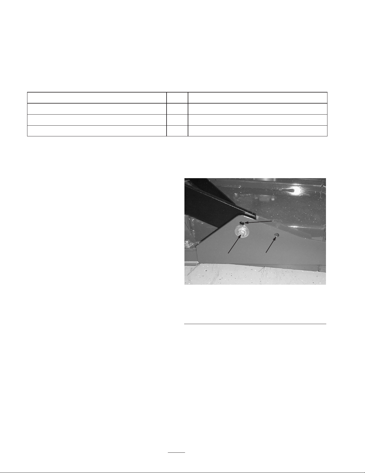
Whenever you need service, genuine Toro parts, or
additional information, contact an Authorized Service
Dealer or Toro Customer Service and have the model and
serial numbers of your product ready. The model and serial
numbers are stamped into a plate on the rear of the mower
deck, under the cover.
Write the product model and serial numbers in the space
below:
Model No.
Serial No.
This manual identifies potential hazards and has special
safety messages that help you and others avoid personal
injury and even death. Danger, Warning, and Caution are
signal words used to identify the level of hazard. However,
regardless of the hazard, be extremely careful.
Danger signals an extreme hazard that will cause serious
injury or death if you do not follow the recommended
precautions.
Warning signals a hazard that may cause serious injury or
death if you do not follow the recommended precautions.
Caution signals a hazard that may cause minor or moderate
injury if you do not follow the recommended precautions.
This manual uses two other words to highlight information.
Important calls attention to special mechanical
information and Note: emphasizes general information
worthy of special attention.

3
Safety
Safety and Instruction Decals
Safety decals and instructions are easily visible to the operator and are located near any area
of potential danger. Replace any decal that is damaged or lost.
98-7818
1. Warning—torque the blade bolt to 85–110 ft.-lb (115–149 N⋅m).
Read the operator’s manual for further instructions.
43-8480
104-1086
1. Height of cut
100-6583
(Affix over decal part no. 43–8480 for CE)
1. Thrown object hazard—stay a safe distance from the machine.
2. Cutting/dismemberment hazard of hand or foot, mower
blade—stay away from moving parts.
104–4892

4
Specifications
Note: Specifications and design subject to change without
notice.
General Specifications
Chamber Construction
Welded 7 GA (.1793 in.),10 GA (.1345 in.) and 12 GA (.1036 in.) steel. Spindle
support is 3/16 in. high-strength steel and 10 GA exterior channels, withstands
multiple blade impact tests. Deck frame is welded 1-1/2 in. square tubing and 7 GA
(.1793 in.) side supports, protects chamber, withstands collisions.
Blade 27” long, combo sail, heat treated steel
Tip Speed 15,400 ft./min. nominal
Blade Plane
(factory pre-set)
Height of Cut 2.00 (5.08 cm)
Right or left side 2.15 (5.46 cm)
Side to side within .09 in. (.23 cm) of each other
Blade rake approximately 5/16 in. (.79 cm)
Height of Cut 3/4–4 in. (1.91–10.16 cm) in 1/4 in. (.64 cm) increments
Deck Drive
Hydraulic integrated relief. High efficiency gear type pump. High efficiency gear
type motor. Recommended oil is Mobil DTE 15M (Mobil EAL biodegradable
compatible).
Spindles 1-1/4 in. (3.17 cm) shaft, greasable, tapered roller bearing, ductile iron housing
which withstands multiple impact tests.
Discharge Rear, even clipping distribution in wet or dry conditions
Mulching Baffle (Optional) Pre-drilled mounting holes provided in decks
Front Rollers Two 5 in. (12.7 cm) diameter, ductile iron w/hollow core, sealed bearings, close
location to blade
Rear Roller One 3 in. (7.6 cm) diameter, steel, exterior shaft seal, full length, close location to
blade
Anti-Scalp Cup 6 in. (15.2 cm) standard
Suspension Non-steering carrier frame
Weight 195 lb. (88 kg)

5
Dimensions
Overall length 34 in. (86.4 cm)
Overall width 34 in. (86.4 cm)
Overall height 9.6 in. (24.4 cm) to carrier
mount
10-1/2 in. (26.7 cm) at 3/4 in.
height of cut
13-3/4 in. (34.9 cm) at 4 in.
height of cut
Roller footprint
Front to back
Rear roller
Front rollers
29.5 in. (74.9 cm)
29.8 in. (75.7 cm) full length
18.5 in. (47 cm) between front
rollers
Optional Equipment
Mulching Baffle Kit
(contains parts for one deck)
Model No. 30836
Atomic Blade Part No.
107–0235–03

6
Setup
Note: Determine the left and right sides of the machine from the normal operating position.
Loose Parts
Note: Use this chart as a checklist to ensure that all parts have been received. Without these parts, total setup cannot be
completed.
Description Qty. Use
Decal 1 Apply to cutting deck for CE
Parts Catalog 1
Operator’s Manual 1Read before operating the machine.
Adjusting the Carrier Frame
(Groundsmaster 3500 only)
The front and rear cutting decks require different mounting
positions.
The front cutting deck has two mounting positions
depending on what height-of-cut and degree of deck
rotation is desired. The rear cutting deck has one mounting
position for proper alignment with the sidewinder under
frame.
Front Cutting Decks
1. For heights of cut in the 3/4 to 3 inch range, the front
carrier frames should be mounted in the lower front
mounting holes (Fig. 1).
Note: This permits more up travel of the cutting decks
relative to tractor when approaching quick uphill changes
in terrain. It does however limit the clearance of the
chamber to carrier when cresting sharp knolls.
2. For heights of cut in the 2–1/2 to 4 inch range, the front
carrier frames should be mounted in the upper front
mounting holes (Fig. 1).
Note: This increases the chamber to carrier clearance due
to the higher position of the cutting chamber, but will cause
the cutting deck to reach their maximum up travel sooner.
Rear Cutting Decks
For all heights of cut, the rear cutting deck should be
mounted in the rear mounting holes (Fig. 1).
1
2 3
Figure 1
1. Front deck mounting hole (upper)
2. Front deck mounting hole (lower)
3. Rear deck mounting hole

7
Adjusting the Height of Cut
Important This cutting deck often cuts approximately
1/4 inch lower than a reel cutting unit with the same bench
setting. It may be necessary to have these rotary cutting
deck’s bench set 1/4 inch above that of reels cutting in the
same area.
Important Access to the rear cutting units is greatly
improved by removing the cutting unit from the tractor. If
the unit is equipped with a Sidewinder,®sidewind the
cutting units to the right, remove the rear cutting unit, and
slide it out to the right side.
1. Lower cutting deck to ground, stop engine, and remove
key from ignition switch.
2. Loosen capscrew securing each height of cut bracket to
height of cut plate (front and each side) (Fig. 2).
3. Beginning with front adjustment, remove capscrew.
1
2
3
Figure 2
1. Height of cut bracket
2. Height of cut plate
3. Spacer
4. While supporting chamber, remove spacer (Fig. 2).
5. Move chamber to desired height-of-cut and install
spacer into designated height-of-cut hole and slot
(Fig. 3).
Figure 3
6. Position tapped plate in line with spacer.
7. Install capscrew finger tight.
8. Repeat steps 4–7 for each side adjustment.
9. Tighten all three capscrews to 30 ft.-lb. (41 N⋅m).
Always tighten the front capscrew first.
Note: Adjustments of more than 1-1/2 inch may require
temporary assembly to an intermediate height to prevent
binding (e.g. changing from 1.25 in. to 2.75 in.
height-of-cut).
Adjusting the Roller Scraper
(Optional)
The optional rear roller scraper is designed to work best
when there is an even gap of .020–.040 inches between the
scraper and roller.
1. Loosen the top 2 mounting screws and the lower 2
flange nuts (Fig. 4).
m–5417
1
2
3
Figure 4
1. Roller scraper
2. Mounting screw
3. Flange nut
2. Slide the scraper up or down until a gap of .020–.040 in.
is achieved between the rod and the roller.
3. Secure the mounting screws and flange nuts to 30 ft.-lb.
(41 N⋅m) in an alternating sequence.

8
Installing the Mulching Baffle
(Optional)
1. Thoroughly clean debris from mounting holes on rear
wall and left side wall of chamber.
2. Install mulching baffle in rear opening and secure with
5 flange head screws (Fig. 5).
1
Figure 5
1. Mulching baffle
3. Verify that mulching baffle does not interfere with
either tip of blade and does not protrude inside the
surface of the rear chamber wall.
Do not use the high lift blade with the mulching
baffle. The blade could break, resulting in personal
injury or death.
Warning

9
Operation
Note: Determine the left and right sides of the machine
from the normal operating position.
Operating Tips
Blade Selection
Standard Combination Sail
This blade was designed to provide excellent lift and
dispersion in almost any condition. If more or less lift and
discharge velocity is required, a different blade may be
considered.
Attributes:
•Excellent lift and dispersion in most conditions.
Atomic Blade
This blade was designed to provide excellent leaf mulching.
Attributes:
•Excellent leaf mulching
Mow When Grass is Dry
Mow either in the late morning to avoid the dew, which
causes grass clumping, or in late afternoon to avoid the
damage that can be caused by direct sunlight on the
sensitive, freshly mowed grass.
Select the Proper Height-of-Cut Setting to
Suit Conditions
Remove approximately one inch or no more than 1/3 of the
grass blade when cutting. In exceptionally lush and dense
grass you may have to raise your height–of–cut setting
another notch.
Always Start Mowing with Sharp Blades
A sharp blade cuts cleanly and without tearing or shredding
the grass blades like a dull blade. Tearing and shredding
causes the grass to turn brown at the edges which impairs
growth and increases susceptibility to diseases. Make sure
blade is in good condition and a full sail is present.
Check Condition of Deck
Make sure cutting chambers are in good condition.
Straighten any bends in chamber components to assure
correct blade tip/chamber clearance.
After Operating
To ensure optimum performance, clean underside of mower
housing. If residue is allowed to build up in mower
housing, cutting performance will decrease.

10
Maintenance
Note: Determine the left and right sides of the machine from the normal operating position.
Caution
If you leave the key in the ignition switch, someone could accidently start the engine and
seriously injure you or other bystanders.
Remove the key from the ignition before you do any maintenance.
Greasing the Bearings
Each cutting deck has two grease fittings per spindle. Either
fitting can be used, which ever is more accessible. If
machine is operated under normal conditions, lubricate
blade spindle bearings (Fig. 6) with No. 2 general purpose
lithium base grease or molybdenum base grease, after every
50 hours of operation. Pump grease into fitting until a small
amount appears at bottom of spindle housing (under deck).
Figure 6
Each cutting deck has two grease fittings per rear roller If
machine is operated under normal conditions, lubricate rear
roller bearings (Fig. 7) with No. 2 general purpose lithium
base grease or molybdenum base grease, after every 50
hours of operation. The fittings are flush fittings and
require a grease gun nozzle adapter, Toro Part No.
107–1998 which can be obtained from your Authorized
Toro Distributor.
Figure 7

11
Cutting Deck Service Latch
(Groundsmaster 3500–D only)
When servicing cutting decks, use the service latch to
prevent injury.
1. Center cutting deck sidewinder with the traction unit.
2. Raise cutting decks to transport position.
3. Set parking brake and turn off machine.
4. Release latch rod (Fig. 8) from front carrier frame
retainer.
1
Figure 8
1. Service latch hook
5. Lift outside of front cutting decks and place latch over
frame pin mounted on front of operators platform
(Fig. 8).
6. Sit on operator seat and start traction unit.
7. Lower cutting decks to mow position.
8. Turn off machine and remove key.
9. Reverse procedure to unlatch cutting decks.
Separating the Cutting Decks
from the Traction Unit
1. Position machine on level surface, lower cutting decks
to floor, shut engine off, and engage parking brake.
2. Disconnect and remove hydraulic motor from deck
(Fig. 9). Cover top of spindle to prevent contamination.
1
1
Figure 9
1. Motor mounting screws
3. Remove lynch pin or retaining nut (GM4700 only)
securing deck carrier frame to lift arm pivot pin
(Fig. 10).
1
2
Figure 10
1. Lynch pin 2. Lift arm pivot pin
4. Roll the cutting deck away from the traction unit.
Mounting the Cutting Decks to
the Traction Unit
1. Position machine on a level surface and shut engine off.
2. Move cutting deck into position in front of traction unit.
3. Slide deck carrier frame onto lift arm pivot pin. Secure
with lynch pin or retaining nut (GM 4700 only)
(Fig. 10).
4. Install hydraulic motor to deck (Fig. 9). Make sure
O-ring is in position and not damaged.
5. Grease spindle.

12
Blade Plane
The rotary deck comes from the factory preset at 2.00 inch
height-of-cut and blade rake of 0.310 inch. The left-hand
and right-hand heights are also preset to within ±0.030 inch
of the other.
The cutting deck is designed to withstand blade impacts
without deformation of the chamber. If a solid object is
struck, inspect the blade for damage and blade plane for
accuracy.
Inspecting the Blade Plane
1. Remove hydraulic motor from cutting deck and remove
cutting deck from tractor.
2. Use hoist (or minimum of two people) and place cutting
deck on flat table.
3. Mark one end of blade with paint pen or marker. Use
this end of blade to check all heights.
4. Position cutting edge of marked end of blade at 12
o’clock (straight ahead in direction of mowing)
(Fig. 11) and measure height from table to cutting edge
of blade.
12 o’clock
6 o’clock
9 o’clock 3 o’clock
Figure 11
5. Rotate marked end of blade to the 3 and 9 o’clock
positions (Fig. 11) and measure heights.
6. Compare 12 o’clock measured height to the height of
cut setting. It should be within .030 inch. The 3 and 9
o’clock heights should be .150±.090 inch higher than
the 12 o’clock setting and within .090 in. of each other.
If any of these measurements are not within specification,
proceed to Adjusting the Blade Plane, page 12.
Adjusting the Blade Plane
Start with front adjustment (change one bracket at a time).
1. Remove height-of-cut bracket, (front, left, or right)
from deck frame (Fig. 12).
2. Adjust .060 in. shims and/or .030 in. shim between the
deck frame and bracket to achieve the desired height
setting (Fig. 12).
1
2
Figure 12
1. Height of cut bracket 2. Shims
3. Install height-of-cut bracket to deck frame with
remaining shims assembled below the height-of-cut
bracket.
4. Secure socket head bolt/spacer and flange nut.
Note: Socket head bolt/spacer are held together with
Loctite to prevent spacer from falling inside the deck
frame.
5. Verify 12 o’clock height and adjust if needed.
6. Determine if only one or both (right-hand and left-hand)
height-of-cut brackets need to be adjusted. If the 3 or 9
o’clock side is .150±.090 in. higher than the new front
height then no adjustment is needed for that side. Adjust
other side to within ±.090 in. of correct side.
7. Adjust right and/or left height-of-cut brackets by
repeating steps 1 thru 3.
8. Secure carriage bolts and flange nuts.
9. Again, verify 12, 3, and 9 o’clock heights.

13
Removing the Cutter Blade
The blade must be replaced if a solid object is hit, the blade
is out of balance or if the blade is bent. Always use genuine
Toro replacement blades to be sure of safety and optimum
performance. Never use replacement blades made by other
manufacturers because they could be dangerous.
1. Raise cutting deck to highest position, shut the engine
off, and engage the parking brake. Block cutting deck to
prevent it from falling accidentally.
2. Grasp end of blade using a rag or thickly padded glove.
Remove blade bolt, anti-scalp cup, and blade from
spindle shaft (Fig. 13).
1
2
Figure 13
1. Blade bolt 2. Anti-scalp cup
3. Install blade, sail facing toward cutting deck, with
anti-scalp cup and blade bolt (Fig. 13). Tighten blade
bolt to 85–110 ft.-lb. (115–149 N⋅m).
Danger
A worn or damaged blade can break, and a piece
of the blade could be thrown into the operator’s or
bystander’s area, resulting in serious personal
injury or death.
•Inspect the blade periodically for wear or
damage.
•Never weld a broken or cracked blade.
•Always replace a worn or damaged blade.
Inspecting and Sharpening the
Blade
1. Raise cutting deck to highest position, shut the engine
off, and engage the parking brake. Block cutting deck to
prevent it from falling accidentally. On the
Groundsmaster 3500, secure cutting deck service latch.
2. Examine cutting ends of the blade carefully, especially
where the flat and curved parts of the blade meet
(Fig. 14-A). Since sand and abrasive material can wear
away the metal that connects the flat and curved parts of
the blade, check the blade before using the machine. If
wear is noticed (Fig. 14-B), replace the blade; refer to
Removing the Cutter Blade, page 13.
Danger
If the blade is allowed to wear, a slot will form
between the sail and flat part of the blade
(Fig. 14-C). eventually a piece of the blade may
break off and be thrown from under the housing,
possibly resulting in serious injury to yourself or
bystanders.
•Inspect the blade periodically for wear or
damage.
•Always replace a worn or damaged blade.
Figure 14
3. Inspect cutting edges of all blades. Sharpen the cutting
edges if they are dull or nicked. Sharpen only the top of
the cutting edge and maintain the original cutting angle
to make sure of sharpness (Fig. 15). The blade will
remain balanced if same amount of metal is removed
from both cutting edges.

14
SHARPEN AT THIS
ANGLE ONLY
END VIEW
Figure 15
4. To check blade for being straight and parallel, lay blade
on a level surface and check its ends. Ends of blade
must be slightly lower than the center, and cutting edge
must be lower than the heel of the blade. This blade will
produce good quality of cut and require minimal power
from the engine. By contrast a blade that is higher at the
ends than the center, or if cutting edge is higher than the
heel, the blade is bent or warped and must be replaced.
5. Install blade, sail facing toward cutting deck, with
anti-scalp cup and blade bolt. Tighten blade bolt to
85–110 ft.-lb. (115–149 N⋅m).
Blade Stopping Time
The blades of the cutting deck are to come to a complete
stop in approximately 5 seconds after the cutting deck
engagement switch is shut down.
Note: Make sure the decks are lowered onto a clean section
of turf or hard surface to avoid thrown dust and debris.
To verify this stopping time, have a second person stand
back from the deck at least 20 feet and watch the blades on
one of the cutting decks. Have the operator shut the cutting
decks down and record the time it takes for the blades to
come to a complete stop. If this time is greater than 7
seconds, the braking valve needs adjustment. Call your
Toro Distributor for assistance in making this adjustment.
Servicing the Front Roller
Inspect front roller for wear, excess wobble or binding.
Service or replace roller or components if any of these
conditions exist.
Disassembly
1. Remove roller mounting bolt (Fig. 16).
2. Insert punch through end of roller housing and drive
opposite bearing out by alternating taps to opposite side
of inner bearing race. There should be a 1/16 in.
(.060 in.) lip of inner race exposed.
1
2
3
4
Figure 16
1. Front roller
2. Mounting bolt
3. Bearing
4. Bearing spacer
3. Push second bearing out in press.
4. Inspect roller housing, bearings, and bearing spacer for
damage (Fig. 16). Replace damaged components and
re-assemble.
Assembly
1. Press first bearing into roller housing (Fig. 16). Press on
outer race only or equally on inner and outer race.
2. Insert spacer (Fig. 16).
3. Press second bearing into roller housing (Fig. 16)
pressing equally on inner and outer race until the inner
race comes in contact with spacer.
4. Install roller assembly into deck frame.
Important Securing roller assembly with a gap larger
than .060 in. creates a side load on bearing and can lead to
premature bearing failure.
5. Verify that there is no more than a .060 in. gap between
roller assembly and the roller mount brackets of the
deck frame. If there is a gap over .060 in., install
enough 5/8 in. diameter washers to take up the slop.
6. Secure mounting bolt to 80 ft.-lb. (108 N⋅m).
Cutting Deck Storage
If cutting deck is separated from traction unit for any length
of time, install spindle plug (94-2703) in top of spindle to
protect spindle from dust and water.

15

The Toro General Commercial Products Warranty
A Two-Year Limited Warranty
Conditions and Products Covered
The Toro Company and its affiliate, Toro Warranty Company,
pursuant to an agreement between them, jointly warrant your Toro
Commercial Product (“Product”) to be free from defects in
materials or workmanship for two years or 1500 operational
hours*, whichever occurs first. Where a warrantable condition
exists, we will repair the Product at no cost to you including
diagnosis, labor, parts, and transportation. This warranty begins
on the date the Product is delivered to the original retail purchaser.
* Product equipped with hour meter
Instructions for Obtaining Warranty Service
You are responsible for notifying the Commercial Products
Distributor or Authorized Commercial Products Dealer from whom
you purchased the Product as soon as you believe a warrantable
condition exists.
If you need help locating a Commercial Products Distributor or
Authorized Dealer, or if you have questions regarding your
warranty rights or responsibilities, you may contact us at:
Toro Commercial Products Service Department
Toro Warranty Company
8111 Lyndale Avenue South
Bloomington, MN 55420-1196
952-888-8801 or 800-982-2740
E-mail: [email protected]
Owner Responsibilities
As the Product owner, you are responsible for required mainte-
nance and adjustments stated in your operator’s manual. Failure
to perform required maintenance and adjustments can be grounds
for disallowing a warranty claim.
Items and Conditions Not Covered
Not all product failures or malfunctions that occur during the
warranty period are defects in materials or workmanship. This
express warranty does not cover the following:
•Product failures which result from the use of non-Toro
replacement parts, or from installation and use of add-on,
modified, or unapproved accessories
•Product failures which result from failure to perform required
maintenance and/or adjustments
•Product failures which result from operating the Product in an
abusive, negligent or reckless manner
•Parts subject to consumption through use unless found to be
defective. Examples of parts which are consumed, or used up,
during normal Product operation include, but are not limited to,
blades, reels, bedknives, tines, spark plugs, castor wheels,
tires, filters, belts, and certain sprayer components such as
diaphragms, nozzles, and check valves, etc.
•Failures caused by outside influence. Items considered to be
outside influence include, but are not limited to, weather,
storage practices, contamination, use of unapproved coolants,
lubricants, additives, or chemicals, etc.
•Normal “wear and tear” items. Normal “wear and tear” includes,
but is not limited to, damage to seats due to wear or abrasion,
worn painted surfaces, scratched decals or windows, etc.
Parts
Parts scheduled for replacement as required maintenance are
warranted for the period of time up to the scheduled replacement
time for that part.
Parts replaced under this warranty become the property of Toro.
Toro will make the final decision whether to repair any existing part
or assembly or replace it. Toro may use factory remanufactured
parts rather than new parts for some warranty repairs.
General Conditions
Repair by an Authorized Toro Distributor or Dealer is your sole
remedy under this warranty.
Neither The Toro Company nor Toro Warranty Company is
liable for indirect, incidental or consequential damages in
connection with the use of the Toro Products covered by this
warranty, including any cost or expense of providing substi-
tute equipment or service during reasonable periods of
malfunction or non-use pending completion of repairs under
this warranty. Except for the Emissions warranty referenced
below, if applicable, there is no other express warranty. All
implied warranties of merchantability and fitness for use are
limited to the duration of this express warranty.
Some states do not allow exclusions of incidental or consequential
damages, or limitations on how long an implied warranty lasts, so
the above exclusions and limitations may not apply to you.
This warranty gives you specific legal rights, and you may also
have other rights which vary from state to state.
Note regarding engine warranty: The Emissions Control System
on your Product may be covered by a separate warranty meeting
requirements established by the U.S. Environmental Protection
Agency (EPA) and/or the California Air Resources Board (CARB).
The hour limitations set forth above do not apply to the Emissions
Control System Warranty. Refer to the Engine Emission Control
Warranty Statement printed in your operator’s manual or con-
tained in the engine manufacturer’s documentation for details.
Countries Other than the United States or Canada
Customers who have purchased Toro products exported from the United States or Canada should contact their Toro Distributor (Dealer)
to obtain guarantee policies for your country, province, or state. If for any reason you are dissatisfied with your Distributor’s service or
have difficulty obtaining guarantee information, contact the Toro importer. If all other remedies fail, you may contact us at Toro Warranty
Company.
Part No. 374-0031 Rev. C
Other manuals for 30834
2
Table of contents
Other Toro Lawn Mower manuals

Toro
Toro 20351-Serial User manual

Toro
Toro 30074 User manual

Toro
Toro 22200TE User manual

Toro
Toro 74943 User manual

Toro
Toro GrandStand 78596 User manual

Toro
Toro TITAN HD User manual

Toro
Toro Verticutter Reelmaster 5010 Series User manual

Toro
Toro 04130 Greensmaster 500 User manual

Toro
Toro Recycler 20332 User manual

Toro
Toro TimeCutter HD X4850 User manual