Toro Groundsmaster 3200 Series User manual

FormNo.3443-939RevC
60inor72inRearDischarge
RotaryMower
Groundsmaster®3200or3300Series
TractionUnit
ModelNo.31971—SerialNo.407970000andUp
ModelNo.31973—SerialNo.407850000andUp
Registeratwww.Toro.com.
OriginalInstructions(EN)*3443-939*

ThisproductcomplieswithallrelevantEuropean
directives.Fordetails,pleaseseetheDeclarationof
Incorporation(DOI)atthebackofthispublication.
WARNING
CALIFORNIA
Proposition65Warning
Useofthisproductmaycauseexposure
tochemicalsknowntotheStateof
Californiatocausecancer,birthdefects,
orotherreproductiveharm.
Introduction
Thisrotary-bladelawncuttingunitismountedto
aride-onmachineandisintendedtobeused
byprofessional,hiredoperatorsincommercial
applications.Itisprimarilydesignedforcuttinggrass
onwell-maintainedlawnsinparks,sportselds,
andoncommercialgrounds.Usingthisproductfor
purposesotherthanitsintendedusecouldprove
dangeroustoyouandbystanders.
Readthisinformationcarefullytolearnhowtooperate
andmaintainyourproductproperlyandtoavoid
injuryandproductdamage.Youareresponsiblefor
operatingtheproductproperlyandsafely.
Visitwww.Toro.comforproductsafetyandoperation
trainingmaterials,accessoryinformation,helpnding
adealer,ortoregisteryourproduct.
Wheneveryouneedservice,genuineT oroparts,or
additionalinformation,contactanAuthorizedService
DealerorT oroCustomerServiceandhavethemodel
andserialnumbersofyourproductready.Figure1
identiesthelocationofthemodelandserialnumbers
ontheproduct.Writethenumbersinthespace
provided.
Important:Withyourmobiledevice,youcan
scantheQRcodeontheserialnumberdecal(if
equipped)toaccesswarranty,parts,andother
productinformation.
g295738
Figure1
1.Modelandserialnumberlocation
ModelNo.
SerialNo.
Thismanualidentiespotentialhazardsandhas
safetymessagesidentiedbythesafety-alertsymbol
(Figure2),whichsignalsahazardthatmaycause
seriousinjuryordeathifyoudonotfollowthe
recommendedprecautions.
g000502
Figure2
1.Safety-alertsymbol
Thismanualuses2wordstohighlightinformation.
Importantcallsattentiontospecialmechanical
informationandNoteemphasizesgeneralinformation
worthyofspecialattention.
©2021—TheToro®Company
8111LyndaleAvenueSouth
Bloomington,MN554202
Contactusatwww.Toro.com.
PrintedintheUSA
AllRightsReserved

Contents
Safety.......................................................................3
GeneralSafety...................................................3
CuttingUnitSafety..............................................3
SafetyandInstructionalDecals..........................4
Setup........................................................................8
1PreparingtheMachine.....................................8
2InstallingtheCEKit..........................................8
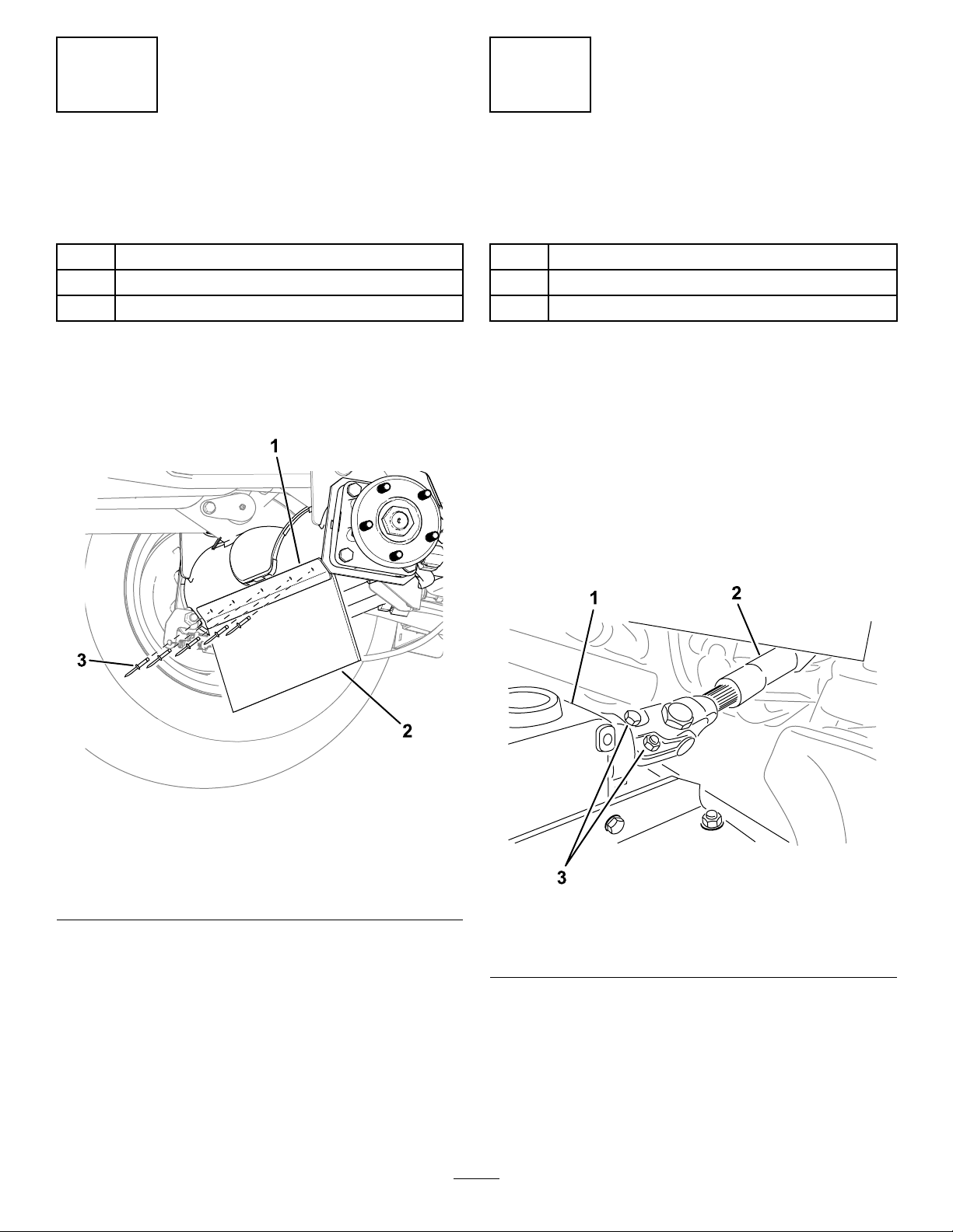
3InstallingtheDebrisGuardtotheFront
Axle.................................................................8
4InstallingtheCuttingUnittotheTraction
Unit.................................................................9
5InstallingthePTOCover................................10
6LevelingtheCuttingUnit................................10
7GreasingtheCuttingUnit................................11
ProductOverview....................................................11
Specications...................................................11
Attachments/Accessories..................................11
Operation................................................................12
AdjustingtheHeightofCut...............................12
AdjustingtheCutting-UnitPitch........................13
AdjustingtheAnti-ScalpRollers........................14
AdjustingtheSkid.............................................14
CorrectingaCuttingUnitMismatch...................14
OperatingTips.................................................15
Maintenance...........................................................16
RecommendedMaintenanceSchedule(s)...........16
DailyMaintenanceChecklist.............................16
GreasingtheBearingsandBushings................17
CheckingtheLubricantintheGearbox..............17
CheckingtheTorqueofthePTO
Driveshaft-to-GearboxFasteners..................17
RemovingtheCuttingUnitfromtheTraction
Unit...............................................................18
ServicingtheBushingsintheCastor
Arms.............................................................19
ServicingtheCastorWheelsand
Bearings........................................................19
ServicingtheCuttingBlades.............................19
CheckingandCorrectingMismatchof
Blades...........................................................21
ReplacingtheDriveBelt...................................22
CleaningUndertheCuttingUnit........................22
Storage...................................................................23
Safety
Thismachinehasbeendesignedinaccordancewith
ENISO5395(whenequippedwiththeCEKit)and
ANSIB71.4-2017.
GeneralSafety
Thisproductiscapableofamputatinghandsand
feetandofthrowingobjects.Alwaysfollowallsafety
instructionstoavoidseriouspersonalinjury
•Readandunderstandthecontentsofthis
Operator’sManualbeforestartingthemachine.
•Useyourfullattentionwhileoperatingthe
machine.Donotengageinanyactivitythat
causesdistractions;otherwise,injuryorproperty
damagemayoccur.
•Donotputyourhandsorfeetnearmoving
componentsofthemachine.
•Donotoperatethemachinewithoutallguards
andothersafetyprotectivedevicesinplaceand
functioningproperlyonthemachine.
•Keepclearofanydischargeopening.
•Keepbystandersandchildrenoutoftheoperating
area.Neverallowchildrentooperatethemachine.
•Beforeyouleavetheoperator’sposition,dothe
following:
–Parkthemachineonalevelsurface.
–Lowerthecuttingunit(s).
–Disengagethedrives.
–Engagetheparkingbrake(ifequipped).
–Shutofftheengineandremovethekey.
–Waitforallmovementtostop.
Improperlyusingormaintainingthismachinecan
resultininjury.Toreducethepotentialforinjury,
complywiththesesafetyinstructionsandalways
payattentiontothesafety-alertsymbol,which
meansCaution,Warning,orDanger—personalsafety
instruction.Failuretocomplywiththeseinstructions
mayresultinpersonalinjuryordeath.
CuttingUnitSafety
•Thecuttingunitisonlyacompletemachinewhen
installedonatractionunit.Readthetraction
unitOperator’sManualcarefullyforcomplete
instructionsonthesafeuseofthemachine.
•Stopthemachine,removethekey,andwaitfor
allmovingpartstostopbeforeinspectingthe
attachmentafterstrikinganobjectorifthereis
anabnormalvibrationinthemachine.Makeall
necessaryrepairsbeforeresumingoperation.
3

•Keepallpartsingoodworkingconditionandall
hardwaretightened.Replaceallwornordamaged
decals.
•Useonlyaccessories,attachments,and
replacementpartsapprovedbyToro.
SafetyandInstructionalDecals
Safetydecalsandinstructionsareeasilyvisibletotheoperatorandarelocatednearanyarea
ofpotentialdanger.Replaceanydecalthatisdamagedormissing.
decal93-6697
93-6697
1.ReadtheOperator's
Manual.
2.AddSAE80w-90(API
GL-5)oilevery50hours.
decal93-7818
93-7818
1.Warning—readtheOperator'sManualforinstructionson
torquingthebladebolt/nutto115to149N∙m(85to110
ft-lb).
decal117-4979
117–4979
1.Entanglementhazard,belt—stayawayfrommovingparts,
keepallguardsandshieldsinplace.
decal120-6604
120-6604
1.Thrownobjecthazard—keepbystandersawayfromthe
machine.
2.Cutting/dismembermenthazardofhand,mower
blade—stayawayfrommovingparts,keepallguardsand
shieldsinplace.
3.Cutting/dismembermenthazardoffoot,mowerblade—stay
awayfrommovingparts,keepallguardsandshieldsin
place.
4

decal127-0326
127-0326
1.ReadtheOperator's
Manual.
3.Removethekeyand
readtheOperator's
Manualbeforeperforming
maintenance.
2.Heightofcut
decal133-8061
133-8061
decal138-7359
138-7359
1.Greaseevery50hours.2.Beltrouting
decal139-6303
139-6303
1.Entanglementhazard—readtheOperator’sManual;stay
awayfrommovingparts;keepallguardsandshieldsin
place.
Model31973only:
decal144-0540
144-0540
1.Heightofcut
5

Model31973only:
decal144-0541
144-0541
1.Heightofcut
Model31971only:
decal144-0542
144-0542
1.Heightofcut
Model31971only:
decal144-0543
144-0543
1.Heightofcut
6

decal137-5949
137-5949
1.Heightofcut2.Mountingholes
7

Setup
LooseParts
Usethechartbelowtoverifythatallpartshavebeenshipped.
ProcedureDescriptionQty.Use
1Nopartsrequired–Preparethemachine.
2Nopartsrequired–InstalltheCEkit(ifrequired).
Debrisguard1
Bracket1
3Rivet5
Installthedebrisguardtothefrontaxle.
Hex-headbolt2
Washer2
4Height-of-cutpin2
Installthecuttingunittothetractionunit.
Shoulderbolt2
5Spacer2InstallthePTOcover.
6Nopartsrequired–Levelthecuttingunit.
7Nopartsrequired–Greasethecuttingunit.
WARNING
Ifyouleavethekeyintheswitch,someonecouldaccidentallystarttheengineandseriously
injureyouorotherbystanders.
Removethekeyfromtheswitchbeforeyouinstallthecuttingunit
DANGER
IftheengineisstartedandthePTOshaftis
allowedtorotate,seriousinjurycouldresult.
DonotstarttheengineandengagethePTO
switchwhenthePTOshaftisnotconnected
tothegearboxonthecuttingunit.
Note:Determinetheleftandrightsidesofthe
machinefromthenormaloperatingposition.
1
PreparingtheMachine
NoPartsRequired
Procedure
1.Parkthemachineonalevelsurface.
2.Engagetheparkingbrake.
3.Shutofftheengineandremovethekey.
2
InstallingtheCEKit
IfRequired(CE-Compliant
CountriesOnly)
NoPartsRequired
Procedure
Ifyouusethismachineinacountrythatcomplies
toCEstandards,installtheCEKit;refertothekit
InstallationInstructions.
8

3
InstallingtheDebrisGuard
totheFrontAxle
Partsneededforthisprocedure:
1Debrisguard
1Bracket
5Rivet
Procedure
Use5rivetstoinstallthebracketanddebrisguardto
thefrontaxle(Figure3).
g312858
Figure3
Leftsideofthemachineshown.
1.Bracket3.Rivet
2.Debrisguard
4
InstallingtheCuttingUnit
totheTractionUnit
Partsneededforthisprocedure:
2Hex-headbolt
2Washer
2Height-of-cutpin
Procedure
1.Parkthemachineonalevelsurface,move
theliftarmstothelowestposition,engagethe
parkingbrake,shutofftheengine,andremove
thekey.
2.Positionthecuttingunitinfrontofthetraction
unit.
3.SlidethePTO-shaftyokeontothegearboxshaft
andsecuretheshaftstogetherwith2boltsand
nutsinoppositedirections(Figure4).
g299646
Figure4
1.Gearbox3.Boltsandnuts
2.PTOshaft
4.Tightentheboltsandnuts(Figure4);refer
tothemachineOperator'sManualfortorque
specications.
5.Pushaliftarmdownuntiltheholesintheliftarm
lineupwiththeholesinthecastorarms,then
insertawasherandboltthroughbotharms.
6.Alignthelift-armholeswiththecastor-armholes.
9

7.Use2hex-headboltsand2washerstosecure
thecastorarmstotheliftarms(Figure5).
Ifyouhavepreviouslyusedtheboltsto
installthecuttingunit:Applythread-locking
compoundtothethreadsofthebolts.
g296375
Figure5
1.Liftarm3.Washer
2.Castorarm4.Bolt
8.Torquetheboltstotheappropriatespecication:
•Ifyouareusingtheboltstoinstallthecutting
unitforthersttime:
Torquetheboltsto256to313N∙m(189to
231ft-lb).
•Ifyouhavepreviouslyusedtheboltsto
installthecuttingunit:
Torquetheboltsto195to239N∙m(144to
176ft-lb).
9.Settheheightofcut;refertoAdjustingthe
HeightofCut(page12).
5
InstallingthePTOCover
Partsneededforthisprocedure:
2Shoulderbolt
2Spacer
Procedure
Use2shoulderboltsand2spacerstosecurethePTO
covertothegearbox(Figure6).
g296657
Figure6
1.Shoulderbolt3.PTOcover
2.Spacer
6
LevelingtheCuttingUnit
NoPartsRequired
Procedure
Note:Performthisprocedureonaat,levelsurface.
1.Rotatethebladeoneachouterspindleuntilthe
endsfaceforwardandbackward.
2.Measurefromtheoortothefronttipofthe
blade.
3.RaisethecuttingunittotheTRANSPORTposition.
4.Adjusttheshimsonthefrontcasterforksto
matchthedesiredheightofcut.
5.Rotatetheblades180°andmeasurefromthe
oortotherear-facingtipoftheblade.
6.Loosenthelowerjamnutsontheheight-of-cut
chainU-bolt(Figure7).
10

g296783
Figure7
1.Jamnuts3.Height-of-cutchain
2.U-bolt
7.Adjustthenuts(Figure7)toraiseorlowerthe
rearofthecuttingunitsothatthetipsoftherear
bladesare6to10mm(1/4to3/8inch)higher
thanthefronttips.
8.Tightenthejamnuts.
7
GreasingtheCuttingUnit
NoPartsRequired
Procedure
Beforeoperatingthecuttingunit,itmustbegreased
toensureproperlubricatingcharacteristics;refer
toGreasingtheBearingsandBushings(page17).
Failuretoproperlygreasethemachinewillresultin
prematurefailureofcriticalparts.
ProductOverview
Specications
Note:Specicationsanddesignaresubjectto
changewithoutnotice.
Width
ofCut
•ModelNo.31971:1.52m(60inches)
•ModelNo.31973:1.82m(72inches)
Height
ofCut
Adjustablefrom25to152mm(1to6inches)in13
mm(1/2inch)increments
Net
Weight
•ModelNo.31971:209kg(460lb)
•ModelNo.31973:236kg(520lb)
Attachments/Accessories
AselectionofT oroapprovedattachmentsand
accessoriesisavailableforusewiththemachine
toenhanceandexpanditscapabilities.Contact
yourAuthorizedServiceDealerorauthorizedToro
distributororgotowww.T oro.comforalistofall
approvedattachmentsandaccessories.
Toensureoptimumperformanceandcontinuedsafety
certicationofthemachine,useonlygenuineT oro
replacementpartsandaccessories.Replacement
partsandaccessoriesmadebyothermanufacturers
couldbedangerous,andsuchusecouldvoidthe
productwarranty.
11

Operation
Note:Determinetheleftandrightsidesofthe
machinefromthenormaloperatingposition.
CAUTION
Ifyouleavethekeyintheignitionswitch,
someonecouldaccidentlystarttheengine
andseriouslyinjureyouorotherbystanders.
Removethekeyfromtheignitionbeforeyou
doanymaintenance.
AdjustingtheHeightofCut
Theheightofcutisadjustablefrom25to152mm(1
to6inches)in13mm(1/2inch)increments.Toadjust
theheightofcut:
1.Parkthemachineonalevelsurface,raisethe
cuttingunittotheTRANSPORTposition,engage
theparkingbrake,shutofftheengine,and
removethekey.
2.Performthefollowingprocedures:
•Positionthecastorwheelaxlesintheupper
orlowerholesofthecastorforks;referto
PositioningtheCastor-WheelAxles(page
12).
•Addorremoveanequalnumberofspacers
fromthecastorforks;refertoPositioningthe
Castor-ForkSpacers(page12).
•Usethepinsinheight-of-cutplatestoposition
thelift-armchains;refertoPositioningthe
Height-of-CutChain(page13).
PositioningtheCastor-Wheel
Axles
Positionthecastor-wheelaxlesinthesameholesin
bothcastorforks.RefertoFigure8andFigure9to
determinethecorrectholesforthesetting.
g031661
Figure8
1.Tensioningcap4.Axlemountingholes
2.Spacers5.Castorwheel
3.Shims
g296889
Figure9
1.Castorwheelheight-of-cut
mountingholes
2.Castorforkheight-of-cut
spacers
Note:Ifyouoperatewitha64mm(2-1/2inch)height
ofcutorhigher,settheaxleboltinthelowerholeto
preventgrassbuildup.Ifyoudetectgrassbuildup
whileoperating,reversethemachinedirectiontopull
anyclippingsawayfromthewheel/forkarea.
PositioningtheCastor-Fork
Spacers
1.Removethetensioningcapfromthespindle
shaft(Figure8)andslidethespindleoutofthe
castorarm.Putthe2shimsontothespindle
shaftastheywereoriginallyinstalled.These
shimsarerequiredtoachievealevelacrossthe
entirewidthofthecuttingunits.
2.Slidetheappropriatenumberofspacersonto
thespindleshafttogetthedesiredheightofcut
(Figure8).
12

RefertoFigure9todeterminethecombinations
ofspacersforyourdesiredheight-of-cutsetting.
Note:Youmayusetheshimsinany
combinationaboveorbelowthecastor-armhub
(asrequired)toachievethedesiredheightof
cutorcutting-unitlevel.
3.Pushthecastorspindlethroughthecastorarm.
4.Installtheshims(astheywereoriginally
installed)andtheremainingspacersontothe
spindleshaft.
5.Installthetensioningcaptosecuretheassembly.
PositioningtheHeight-of-Cut
Chain
1.Removethepinsthatsecuretheheight-of-cut
chainstotherearofthecuttingunit(Figure10).
g296784
Figure10
1.Height-of-cutchain2.Pin
2.Refertotheheight-of-cutdecaltodeterminethe
appropriateholeforyourdesiredheightofcut.
Note:Thedecal[showninSafetyand
InstructionalDecals(page4)]isadjacentto
eachheight-of-cutplate.
3.Mounttheheight-of-cutchainstothedesired
height-of-cutholewiththepin.
Thepinshouldbeinstalledinthelowest
height-of-cutchainlink.Thechainshouldhang
straightdown(Figure10);itshouldnotbe
twisted.
AdjustingtheCutting-Unit
Pitch
Abladepitchof6to9.5mm(1/4to3/8inch)is
recommended(i.e.,thebackofthebladeplaneis6
to9.5mm(1/4to3/8inch)higherthanthefront).A
pitchlargerthan9.5mm(3/8inch)resultsinless
requiredpower,largerclippings,andapoorerquality
ofcut.Apitchlessthan6mm(1/4inch)resultsin
morerequiredpower,smallerclippingsandabetter
qualityofcut.
1.Parkthemachineonalevelsurface,lowerthe
cuttingunit,engagetheparkingbrake,shutoff
theengine,andremovethekey.
2.Setthecuttingunittothedesiredheight-of-cut.
3.Rotate1bladesothatitpointsstraightforward.
4.Usingashortruler,measurefromtheoorto
thefronttipoftheblade.Rotatethebladetipto
therearandmeasurefromtheoortothetip
oftheblade.
5.Subtractthefrontdimensionfromtherear
dimensiontocalculatethebladepitch.
6.Loosenthejamnutsatthetoporbottomofthe
height-of-cutchainU-bolt(Figure11).
g296783
Figure11
1.Jamnuts3.Height-of-cutchain
2.U-bolt
7.Adjusttheothersetofnutstoraiseorlowerthe
rearofthecuttingunitandattainthecorrect
mower-deckpitch.
8.Tightenthejamnuts.
13

AdjustingtheAnti-Scalp
Rollers
Wheneveryouchangetheheight-of-cut,adjustthe
heightoftheanti-scalprollers(Figure12).
g296901
Figure12
1.Parkthemachineonalevelsurface,lowerthe
cuttingunit,engagetheparkingbrake,shutoff
theengine,andremovethekey.
2.Shutofftheengine,removethekey,andwait
forallmovingpartstostopbeforeleavingthe
operatingposition.
3.Adjusttheanti-scalprollersasshowninFigure
13.
Note:Selectaholesotheanti-scalproller
ispositionedtothenearestcorresponding
height-of-cutdesired.
g296902
Figure13
Frontrollersshown
1.Anti-scalproller3.Flangenut
2.Bushing4.Bolt
AdjustingtheSkid
Mounttheskidinthelowerpositionwhenoperatingin
heightofcutshigherthan64mm(2-1/2inches)and
inthehigherpositionwhenoperatinginheightofcuts
lowerthan64mm(2-1/2inches).
1.Parkthemachineonalevelsurface,lowerthe
cuttingunit,engagetheparkingbrake,shutoff
theengine,andremovethekey.
2.Removetheange-headboltsandnutsfromthe
skid.
3.Movetheskidtothedesiredpositionandsecure
ittothecuttingunitwiththeange-headbolts
andnuts(Figure14).
g296665
Figure14
1.Flange-headbolt3.Nut
2.Skid
CorrectingaCuttingUnit
Mismatch
Duetodifferencesingrassconditionsandthe
counterbalancesettingofthetractionunit,itisadvised
thatgrassbecutandappearancecheckedbefore
formalcuttingisstarted.
1.Parkthemachineonalevelsurface,lowerthe
cuttingunit,engagetheparkingbrake,shutoff
theengine,andremovethekey.
2.Setthecuttingunittothedesiredheightofcut;
refertoOperation(page12).
3.Checkandadjustthefrontandreartraction-unit
tirepressuretothespeciedtirepressureinthe
tractionunitOperator’sManual.
4.Checkforbentblades;refertoCheckingfora
BentBlade(page20).
5.Cutgrassinatestareatodetermineifallcutting
unitsarecuttingatthesameheight.
14

6.Ifcuttingunitadjustmentsarestillneeded,nda
atsurfaceusinga2m(6ft)orlongerstraight
edge.
7.Toeasemeasuringbladeplane,raisetheheight
ofcuttothehighestposition;refertoAdjusting
theHeightofCut(page12).
8.Lowercuttingunitontotheatsurface.Remove
thecoversfromthetopofthecuttingunits.
9.Rotatethebladeoneachspindleuntiltheends
faceforwardandbackward.
10.Measurefromtheoortothefronttipofthe
cuttingedge.
Ifthemeasurementsdonotmatchthedesired
heightofcutandpitch,refertoAdjustingthe
Cutting-UnitPitch(page13).
11.Adjustthecastor-wheelspacerstomatchthe
heightofcutlistedonthecastor-wheeldecal;
refertoPositioningtheCastor-ForkSpacers
(page12).
OperatingTips
FastThrottleSetting/Ground
Speed
Tomaintainenoughpowerforthemachineanddeck
whilemowing,operatetheengineatthefastthrottle
positionandadjustyourgroundspeedforconditions.
Decreasethegroundspeedastheloadonthecutting
bladesincreases.Increasethegroundspeedasthe
loadonthebladesdecreases.
MowingDirection
Alternatemowingdirectiontoavoidmakingrutsin
theturfovertime.Thisalsohelpsdisperseclippings
whichenhancesdecompositionandfertilization.
CuttingSpeed
Toimprovecutquality,useaslowergroundspeed.
AvoidCuttingTooLow
Ifthecuttingwidthofthecuttingunitiswiderthanthe
moweryoupreviouslyused,raisethecuttingheightto
ensurethatuneventurfisnotcuttooshort.
SelecttheProperHeight-of-Cut
SettingtoSuitConditions
Removeapproximately1inch(25mm)orno
morethan1/3ofthegrassbladewhencutting.In
exceptionallylushanddensegrass,youmayhave
toslowdowntheforwardspeedand/orraisethe
height-of-cuttothenexthighersetting.
Important:Ifcuttingmorethan1/3ofthe
grassbladeoff,orinsparselonggrassor
dryconditions,theuseofatsailbladesis
recommendedtoreduceair-bornechaff,debris,
anddeckdrivecomponentstrain.
LongGrass
Ifthegrassiseverallowedtogrowslightlylongerthan
normal,orifitcontainsahighdegreeofmoisture,
raisethecuttingheighthigherthantheusualsetting
andcutthegrass.Then,cutthegrassagainusing
thelower,normalsetting.
KeeptheCuttingUnitClean
Cleanclippingsanddirtfromtheundersideofthe
cuttingunitaftereachuse.Ifgrassanddirtbuildup
insidethecuttingunit,cuttingqualitywilleventually
becomeunsatisfactory.
Toreducetheriskofrehazard,keeptheengine,
mufer,batterycompartment,parkingbrake,cutting
units,andfuelstoragecompartmentfreeofgrass,
leaves,orexcessivegrease.Cleanupanyspilledoil
orfuel.
BladeMaintenance
•Maintainasharpbladethroughoutthecutting
season;asharpbladecutscleanlywithouttearing
orshreddingthegrassblades.T earingand
shreddingturnsgrassbrownattheedges,which
slowsgrowthandincreasesthechanceofdisease.
•Checkthebladesdailyforsharpnessandfor
anywearordamage.Sharpenthebladesas
necessary.
•Ifabladeisdamagedorworn,replaceit
immediatelywithagenuineTororeplacement
blade.RefertoRemovingandInstallingthe
Cutting-UnitBlade(s)(page20).
15

Maintenance
Note:Determinetheleftandrightsidesofthemachinefromthenormaloperatingposition.
RecommendedMaintenanceSchedule(s)
MaintenanceService
IntervalMaintenanceProcedure
Aftertherst2hours•Tightenthecastorwheelnuts.
Aftertherst10hours•CheckthePTOdriveshaft-to-gearboxfastenertorque.
•Tightenthecastorwheelnuts.
Aftertherst50hours•Changethegearboxlubricant.
Beforeeachuseordaily•Lubricatethecastorarmbushings.
•Cleanthecuttingunit.
Every50hours
•Lubricatethegreasettings.Lubricatethegreasettingsimmediatelyafterevery
washing.
•Checkthegearboxlubricant.
•Tightenthecastorwheelnuts.
•Checkthebladedrivebeltadjustment.
•Cleanunderthecuttingunitbeltcovers.
Every100hours•CheckthePTOdriveshaft-to-gearboxfastenertorque.
Every400hours•Changethegearboxlubricant.
DailyMaintenanceChecklist
Duplicatethispageforroutineuse.
Fortheweekof: MaintenanceCheckItem
Mon.Tues.Wed.Thurs.Fri.Sat.Sun.
Checktheconditionofthe
blades
Lubricateallgreasettings1
Touch-updamagedpaint
1.Immediatelyaftereverywashing,regardlessoftheintervallisted.
NotationforAreasofConcern
Inspectionperformedby:
ItemDateInformation
CAUTION
Ifyouleavethekeyintheignitionswitch,someonecouldaccidentlystarttheengineand
seriouslyinjureyouorotherbystanders.
Removethekeyfromtheignitionbeforeyoudoanymaintenance.
16

GreasingtheBearingsand
Bushings
ServiceInterval:Every50hoursLubricatethe
greasettingsimmediatelyafter
everywashing.
Themachinehasgreasettingsthatyoumust
lubricateregularlywithNo.2lithiumgrease.
1.Parkthemachineonalevelsurface,lowerthe
cuttingunit,engagetheparkingbrake,shutoff
theengine,andremovethekey.
2.Lubricatethefollowingareas:
•Castorforkshaftbushings(4)(Figure15).
g011557
Figure15
•Spindleshaftbearings(3—locatedunderthe
pulley)(Figure16)
g296805
Figure16
•Idlerarmshaftbearings(Figure16)
CheckingtheLubricantin
theGearbox
ServiceInterval:Every50hours
Aftertherst50hours
Every400hours
ThegearboxindesignedtooperateonSAE80-90
weightgearlube.Althoughthegearboxcomeswith
lubricantfromthefactory,checkthelevelbefore
operatingthecuttingunit.Thegearboxcapacityis
283ml(15oz).
1.Parkthemachineonalevelsurface,lowerthe
cuttingunit,engagetheparkingbrake,shutoff
theengine,andremovethekey.
2.Removethedipstick/llplugfromthetopof
thegearbox(Figure17)andensurethatthe
lubricantisbetweenthemarksonthedipstick.If
thelubricantlevelislow,addenoughlubricant
untilthelevelisbetweenthemarks.
g010548
Figure17
1.Dipstick/llplug
3.Installthedipstickandtorqueitto9N∙m(84
in-lbs).
CheckingtheTorqueofthe
PTODriveshaft-to-Gearbox
Fasteners
ServiceInterval:Aftertherst10hours
Every100hours
Checkthetorqueofthefastenersthatsecurethe
PTOdriveshafttothegearbox(Figure18);refertothe
setupsectioninyourmachineOperator’sManualfor
theappropriatetorquespecication.
17

g299646
Figure18
1.Gearbox3.PTOdriveshaft
2.Boltsandnuts
RemovingtheCuttingUnit
fromtheTractionUnit
1.Parkthemachineonalevelsurfacewiththe
cuttingunitraised.
2.Removetheheight-of-cutpins(Figure19)from
thecutting-unitsideplates.
g296784
Figure19
1.Height-of-cutchain2.Pin
3.Lowerthecuttingunit,engagetheparking
brake,shutofftheengine,andremovethekey.
4.Removetheboltsandwashersthatsecurethe
liftarmstothecastorarms.
g296375
Figure20
1.Liftarm3.Washer
2.Castorarm4.Bolt
5.RemovetheboltsandnutsfromthePTOshaft
(Figure21)andslidetheyokeoutofthegearbox.
Note:RefertotheOperator’sManual,to
properlyalignthesplinesifyouseparatethe
driveshaftcomponents.
g299646
Figure21
1.Gearbox3.Boltsandnuts
2.PTOshaft
18

ServicingtheBushingsin
theCastorArms
Thecastorarmshavebushingspressedintothetop
andbottomofthetube,andaftermanyhoursof
operation,thebushingswear.
Tocheckthebushings,movethecastorforkback
andforthandfromsidetoside.Ifthecastorspindle
islooseinsidethebushings,thebushingsareworn;
replacethem.
1.Parkthemachineonalevelsurface,lowerthe
cuttingunit,engagetheparkingbrake,shutoff
theengine,andremovethekey.
2.Removethetensioningcap,spacer(s),and
thrustwasherfromthetopofthecastorspindle.
3.Pullthecastorspindleoutofthemountingtube.
Allowthethrustwasherandspacer(s)toremain
onthebottomofthespindle.
4.Insertapinpunchintothetoporbottomofthe
mountingtubeanddrivethebushingoutofthe
tube(Figure22).Also,drivetheotherbushing
outofthetube.Cleantheinsideofthetubes
toremovedirt.
g004737
Figure22
1.Castorarmtube2.Bushings
5.Applygreasetotheinsideandoutsideofthe
newbushings.Useahammerandatplateto
drivethebushingsintothemountingtube.
6.Inspectthecastorspindleforwearandreplace
itifdamaged.
7.Pushthecastorspindlethroughthebushings
andmountingtube,slidethethrustwasher
andspacer(s)ontothespindle,andinstallthe
tensioningcaponthecastorspindle.
ServicingtheCastor
WheelsandBearings
1.Parkthemachineonalevelsurface,lowerthe
cuttingunit,engagetheparkingbrake,shutoff
theengine,andremovethekey.
2.Removethelocknutfromtheboltholdingthe
castorwheelassemblybetweenthecastorfork
(Figure23).Graspthecastorwheelandslide
theboltoutoftheforkorpivotarm.
3.Removethebearingfromthewheelhuband
allowthebearingspacertofallout(Figure23).
Removethebearingfromtheoppositesideof
thewheelhub.
4.Checkthebearings,spacer,andinsideofthe
wheelhubforwear.Replaceanydamaged
parts.
5.T oassemblethecastorwheel,pushthebearing
intothewheelhub.Wheninstallingthebearings,
pressontheouterraceofthebearing.
g004738
Figure23
1.Castorwheel3.Bearings
2.Castorfork4.Bearingspacer
6.Slidethebearingspacerintothewheelhub.
Pushtheotherbearingintotheopenendofthe
wheelhubtocaptivatethebearingspacerinside
thewheelhub.
7.Installthecastorwheelassemblybetweenthe
castorforkandsecureitinplacewiththebolt
andlocknut.
ServicingtheCutting
Blades
BladeSafety
Awornordamagedbladecanbreak,andapieceof
thebladecouldbethrowntowardyouorbystanders,
resultinginseriouspersonalinjuryordeath.
•Inspectthebladeperiodicallyforwearordamage.
•Usecarewhencheckingtheblades.Wrapthe
bladesorweargloves,andusecautionwhen
19

servicingtheblades.Onlyreplaceorsharpenthe
blades;neverstraightenorweldthem.
•Onmulti-bladedmachines,takecareasrotating1
bladecancauseotherbladestorotate.
CheckingforaBentBlade
Afterstrikingaforeignobject,inspectthemachine
fordamageandmakerepairsbeforestarting
andoperatingtheequipment.T orqueallofthe
spindle-pulleynutsto176to203N∙m(130to150
ft-lb).
1.Parkthemachineonalevelsurface,raisethe
cuttingunittotheTRANSPORTposition,engage
theparkingbrake,shutofftheengine,and
removethekey.
2.RaisethecuttingunittotheSERVICEposition;
refertoyourtractionunitOperator’sManual.
3.Rotatethebladeuntiltheendsfaceforwardand
backwardandmeasurefromtheinsideofthe
cuttingunittothecuttingedgeatthefrontofthe
blade(Figure24).
Note:Rememberthisdimension.
g004740
Figure24
4.Rotatetheoppositeendofthebladeforward
andmeasurebetweenthecuttingunitand
cuttingedgeofthebladeatthesameposition
asinstep3.
Note:Thedifferencebetweenthedimensions
obtainedinsteps3and4mustnotexceed3mm
(1/8inch).Ifthedimensionexceeds3mm(1/8
inch),thebladeisbentandmustbereplaced;
refertoRemovingandInstallingtheCutting-Unit
Blade(s)(page20).
RemovingandInstallingthe
Cutting-UnitBlade(s)
Replacethebladeifithitsasolidobject,isout
ofbalance,orisbent.AlwaysusegenuineT oro
replacementbladestoensuresafetyandoptimum
performance.
1.Parkthemachineonalevelsurface,raisethe
cuttingunittotheTRANSPORTposition,engage
theparkingbrake,shutofftheengine,and
removethekey.
2.RaisethecuttingunittotheSERVICEposition;
refertoyourtractionunitOperator’sManual.
3.Grasptheendofthebladeusingaragor
thickly-paddedglove.
4.Removethebladebolt,anti-scalpcup,and
bladefromthespindleshaft(Figure25).
g004741
Figure25
1.Bladebolt2.Anti-scalpcup
5.Installtheblade,anti-scalpcup,andbladebolt
andtightenthebladeboltto115to149N∙m(85
to110ft-lb).
Important:Thecurvedpartoftheblade
mustbepointingtowardtheinsideofthe
cuttingunittoensurepropercutting.
Note:Afterstrikingaforeignobject,torqueall
spindle-pulleynutsto115to149N∙m(85to110
ft-lb).
InspectingandSharpeningthe
CuttingUnitBlade(s)
Bothcuttingedgesandthesail,whichistheturned-up
portionoppositeofthecuttingedge,contributetoa
goodqualityofcut.
Maintainsharpbladesthroughoutthecuttingseason.
Sharpbladescreateacleancutwithouttearingor
shreddingthegrassblades.
Checkthebladesforanywearordamage.Thesail
liftsthegrassupstraight,therebyproducinganeven
cutandgraduallywearsdownduringoperation.
1.Parkthemachineonalevelsurface,raisethe
cuttingunittotheTRANSPORTposition,engage
theparkingbrake,shutofftheengine,and
removethekey.
2.RaisethecuttingunittotheSERVICEposition;
refertoyourtractionunitOperator’sManual.
3.Examinethecuttingendsofthebladecarefully,
especiallywheretheatandcurvedpartsofthe
blademeet(Figure26).
Note:Becausesandandabrasivematerial
canwearawaythemetalthatconnectstheat
andcurvedpartsoftheblade,checktheblade
beforeusingthemower.Ifyounoticewear
(Figure26),replacetheblade.
20
Other manuals for Groundsmaster 3200 Series
1
This manual suits for next models
3
Table of contents
Other Toro Lawn Mower manuals

Toro
Toro Greenmaster 1000 User manual

Toro
Toro ProLine 30159 User manual

Toro
Toro 22293 User manual

Toro
Toro TITAN ZX5450 User manual

Toro
Toro Super Recycler 21681 User manual

Toro
Toro Z Master Professional 7500-DSeries User manual

Toro
Toro Recycler 20996 User manual

Toro
Toro GrandStand 74568TE User manual

Toro
Toro 20065 User manual

Toro
Toro Greensmaster e1021 User manual