manuals.online logo
Brands
  1. Home
  2. •
  3. Brands
  4. •
  5. Toro
  6. •
  7. Lawn Mower
  8. •
  9. Toro TimeCutter Z Manual

Toro TimeCutter Z Manual

This manual suits for next models

4

Other Toro Lawn Mower manuals

Toro Grandstand 18562 User manual

Toro

Toro Grandstand 18562 User manual

Toro wheel horse 416H User manual

Toro

Toro wheel horse 416H User manual

Toro 20959 User manual

Toro

Toro 20959 User manual

Toro ProLine 44448 User manual

Toro

Toro ProLine 44448 User manual

Toro GrandStand 74553 User manual

Toro

Toro GrandStand 74553 User manual

Toro Groundsmaster 4500-D User manual

Toro

Toro Groundsmaster 4500-D User manual

Toro ProLine 30167 User manual

Toro

Toro ProLine 30167 User manual

Toro Recycler 20376 User manual

Toro

Toro Recycler 20376 User manual

Toro 20068 User manual

Toro

Toro 20068 User manual

Toro 74453TE User manual

Toro

Toro 74453TE User manual

Toro Z Master Series Manual

Toro

Toro Z Master Series Manual

Toro 2656 User manual

Toro

Toro 2656 User manual

Toro 30261TE User manual

Toro

Toro 30261TE User manual

Toro HoverPro 400 User manual

Toro

Toro HoverPro 400 User manual

Toro 20099 User manual

Toro

Toro 20099 User manual

Toro 03673 Reelmaster 5410-G User manual

Toro

Toro 03673 Reelmaster 5410-G User manual

Toro 3806 User manual

Toro

Toro 3806 User manual

Toro 74176TE User manual

Toro

Toro 74176TE User manual

Toro 73561SEI Manual

Toro

Toro 73561SEI Manual

Toro Groundsmaster 4110 User manual

Toro

Toro Groundsmaster 4110 User manual

Toro 20340 User manual

Toro

Toro 20340 User manual

Toro Recycler 20332 User manual

Toro

Toro Recycler 20332 User manual

Toro XT Series User manual

Toro

Toro XT Series User manual

Toro 04060 Greensmaster 1600 User manual

Toro

Toro 04060 Greensmaster 1600 User manual

Popular Lawn Mower manuals by other brands

Global garden products 72 Workshop manual

Global garden products

Global garden products 72 Workshop manual

EINHELL 01045 operating instructions

EINHELL

EINHELL 01045 operating instructions

Baroness LM315GC Owner's operating manual

Baroness

Baroness LM315GC Owner's operating manual

GreenWorks Tools 25157 user manual

GreenWorks Tools

GreenWorks Tools 25157 user manual

Etesia MVEHH user manual

Etesia

Etesia MVEHH user manual

Husqvarna LTH125 owner's manual

Husqvarna

Husqvarna LTH125 owner's manual

Gravely 915034 - ZT1640 Owner's/operator's manual

Gravely

Gravely 915034 - ZT1640 Owner's/operator's manual

Jacobsen 63281 Technical manual

Jacobsen

Jacobsen 63281 Technical manual

GreenWorks Pro MO802524 Operator's manual

GreenWorks Pro

GreenWorks Pro MO802524 Operator's manual

Deutz-Allis 3000 Series parts manual

Deutz-Allis

Deutz-Allis 3000 Series parts manual

Craftsman 917.9998C owner's manual

Craftsman

Craftsman 917.9998C owner's manual

jobmate YT9108 user manual

jobmate

jobmate YT9108 user manual

Yard force GM R40A instructions

Yard force

Yard force GM R40A instructions

Husqvarna R 419TsX AWD Operator's manual

Husqvarna

Husqvarna R 419TsX AWD Operator's manual

STERWINS ELM2-36P-3W.4 Assemby - Use - Maintenance Manual

STERWINS

STERWINS ELM2-36P-3W.4 Assemby - Use - Maintenance Manual

Craftsman 917.378770 owner's manual

Craftsman

Craftsman 917.378770 owner's manual

Partner M6556SMD Repair parts manual

Partner

Partner M6556SMD Repair parts manual

Craftsman 25913 instruction manual

Craftsman

Craftsman 25913 instruction manual

manuals.online logo
manuals.online logoBrands
  • About & Mission
  • Contact us
  • Privacy Policy
  • Terms and Conditions

Copyright 2025 Manuals.Online. All Rights Reserved.

1
All Rights Reserved
Printed in the USA
2001 by The Toro Company
8111 Lyndale Avenue South
Bloomington, MN 55420-1196
TimeCutterZ Riding Mowers
Model No. 74501—Serial No. 220000001 and Up
Model No. 74601—Serial No. 220000001 and Up
Model No. 74701—Serial No. 220000001 and Up
Model No. 74801—Serial No. 220000001 and Up
Form No. 3326-793
Setup Instructions
Loose Parts
Note: Use the chart below to verify that all parts have been shipped.
Description Qty. Use
Bolt, 1/4 x 3/4 in.
Washer, 1/4 in.
Nut, 1/4 in.
2
2
2Installing the battery
Seat
Knob
Flat washer, 5/16 in.
1
2
2Installing the seat
Left-hand control lever
Right-hand control lever
Bolt, 3/8 x 1 in.
Curved washer, 3/8 in.
1
1
4
4
Installing the motion control levers
Hose coupling 1Washing the underside of the mower
Key 1
Operator’s Manual
Engine Operator’s Manual 1
1Read before operating the machine.
Registration card 1Fill out and return to Toro.
2
Activating the Battery
Bulk electrolyte with 1.260 specific gravity must be
purchased from a local battery supply outlet.
Danger
Battery electrolyte contains sulfuric acid which is
a deadly poison and causes severe burns.
•Do not drink electrolyte and avoid contact with
skin, eyes or clothing. Wear safety glasses to
shield your eyes and robber gloves to protect
your hands.
•Fill the battery where clean water is always
available for flushing the skin.
•Follow all instructions and comply with all
safety messages on the electrolyte container.
1. Remove the battery from the machine and place it on a
level surface; refer to the Operator’s Manual,
Removing the Battery.
Important Never fill the battery with electrolyte while
the battery is installed in the tractor. Electrolyte could be
spilled on other parts and cause corrosion.
2. Clean the top of the battery with a paper towel.
3. Remove the vent caps from the battery (Fig. 1). Slowly
pour electrolyte into each battery cell until the
electrolyte level is up to the Upper line on the battery
case (Fig. 1).
Important Do not overfill the battery because
electrolyte (sulfuric acid) can cause severe corrosion and
damage to the chassis.
1
2
3
m-5004
Figure 1
1. Vent caps
2. Upper line 3. Lower line
4. Wait five to ten minutes after filling the battery cells.
Add electrolyte, if necessary, until the electrolyte level
is up to the Upper line (Fig. 1) on the battery case.
5. Reinstall the battery vent caps.
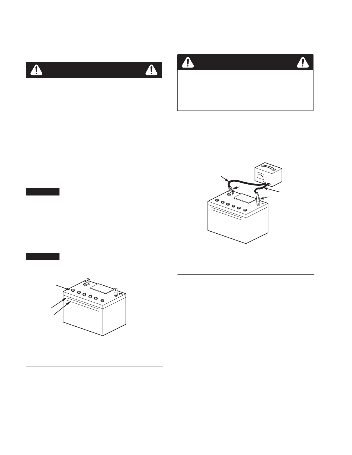
6. Charge the battery for 10 to 15 minutes at 25 to 30
amps or 30 minutes at 4–6 amps (Fig. 2). Do not
overcharge the battery.
Charging the battery produces gasses that can
explode.
Never smoke near the battery and keep sparks
and flames away from battery.
Warning
7. When the battery is fully charged, unplug the charger
from the electrical outlet, then disconnect the charger
leads from the battery posts (Fig. 2).
8. Install the battery in the tractor and connect the battery
cables; refer to the Operator’s Manual, Installing the
Battery.
4
1
23
Figure 2
1. Positive post
2. Negative post 3. Charger red (+) wire
4. Charger black (–) wire
Installing the Motion Control
Levers
1. Remove the 4 bolts (3/8 x 1 in.) and 4 curved washers
(3/8 in.) which attach the motion control levers to the
control arm shafts for shipping (Fig. 3).
2. Place the levers (with the mounting plates toward the
rear of the machine) on the outside of the control arm
shaft and loosely secure them with the 4 bolts and
curved washers removed in step 1 (Fig. 3).
3
m–5215
1
23
4
Figure 3
1. Controlarm
2. Bolt, 3/8 x 1 in. 3. Curved washer, 3/8 in.
4. Control arm shaft
3. Position the levers so that the bolts are in the center of
the slots on the lever mounting plate and tighten the
bolts until they are snug.
4. Align the front/rear position of the levers with each
other while in the neutral position. Loosen the bolts
and adjust the levers by sliding and/or tilting the
lever(s) forward or backward until they are properly
aligned.
5. If the ends of the motion control levers hit against each
other while they are in the drive position (Fig. 4) (the
levers are rotated in as far as possible), make
adjustments by moving the levers outward to the
neutral lock position and carefully bend them outward.
Move them back to the drive position and check for
clearance. Repeat if necessary.
Figure 4
Installing the Seat
1. Cut the plastic ties securing the seat to the machine for
shipping. Remove the seat.
2. Remove the knobs and flat washers (5/16 in.) from the
bottom of the seat.
3. Raise the seat support on the machine (Fig. 5).
4. Slide the shoulder bolts on the bottom of the seat into
the slots on the seat support (Fig. 5). Secure the seat to
the seat support with the flat washers and knobs
removed in step 2 (Fig. 5).
m–5579
1
2
3
Figure 5
1. Seat support
2. Shoulder bolt 3. Knob
5. Lower the seat and adjust it if necessary; refer to
Positioning the Seat in the Operator’s Manual.
Checking the Mower
Adjustment
The mower deck was leveled at the factory. If the mower
is not cutting level, adjust the side-to-side level and the
front-to-rear blade slope. See the Operator’s Manual for
the proper procedure.
Checking the Side Discharge
Chute
Remove the plastic tie holding the side discharge chute
up, and lower the chute into place.
Checking the Engine Oil Level
Before you start the engine and use the machine, check
the oil level in the engine crankcase; refer to Checking the
Oil Level in the Operator’s Manual.
Checking the Tire Pressure
Check the front and rear tires for proper inflation. Refer to
Tire Pressure in the Operator’s Manual for the
recommended inflation pressure.