Toscana OLIOMIO 350-500 FARM Specification sheet

Operation manual OLIOMIO 350-500 FARM 1
TECHNICAL LITERATURE
INSTRUCTIONS FOR USE AND MAINTENANCE
OLIOMIO
350-500 FARM
Manufacturer:
Toscana Enologica Mori S.n.c.
Via Cimabue 4-6 50028 Tavarnelle Val di Pesa (FI) Italy
C. F. / P. I.V.A. 01578280487
Phone 055 8071568 - Fax 055 8071293
ΑΦΟΙ ΓΑΒΡΙΗΛΙΔΗ Α.Ε.Β.Ε.
Σταδίου 101, Τ.Κ. 59100 Βέροια
Τηλ.23310 20262 Fax 23310 20263
http://www.agroenos.com
Ηεταιρεία μας, ΑΦΟΙ ΓΑΒΡΙΗΛΙΔΗ Α.Ε.Β.Ε., ως επίσημος εισαγωγέας και
εξουσιοδοτημένος αντιπρόσωπος για όλη την Ελλάδα του ιταλικού
εργοστασίου Toscana Enologica Mori, παρέχει πλήρη τεχνική υποστήριξη
(service, συνεργείο, γνήσια ανταλλακτικά) και εγγύηση 2 ετών σε όλα τα
ελαιοτριβεία ψυχρής έκθλιψης Toscana Enologica Mori υπό την προϋπόθεση
ότι τηρούνται οι οδηγίες ορθής χρήσης και συντήρησης του ελαιοτριβείου,
όπως ορίζονται από την κατασκευάστρια εταιρεία Toscana Enologica Mori.

Operation manual OLIOMIO 350-500 FARM 2
LETTER AT DELIVERY
Kind customer,
•We should like to inform you that the equipment referred to in this document has been designed,
manufactured and tested according to Italian law no. 459, dated 24th July 1996, which acknowledges
the
European Directives concerning safety 89/392/EEC, 91/368/EEC, 93/44/EEC, 93/68/EEC and the
specifications of UNI EN Std. section I and II and UNI EN 294.
With the handbook that follows our intention is to give a description of the sections that make it up,
their
dimensional and technical specifications, the instructions for use and the maintenance procedures.
We are also including the certificate of Conformity as required by Directive 89/392 CE Annex II
Section A.
We wish to confirm that the equipment presents no hazard for the operator, if used according to the
instructions provided, if incorporated in a machine which is, in turn, stated to be in conformity with
directive
89/392 EEC and provided that:
•the guards installed are kept intact;
•the safety devices are kept in operating conditions;
•the specific operator instructions given herein are adhered to;
•the periodical maintenance operations are carried out and the components are checked as to their
state of
wear and damage;
•the equipment is used within the foreseen operating parameters and with the machines for which it
has been
designed and made;
While thanking you for your preference, we wish you profitable work.
Signature
The descriptions and illustrations herein are not to be considered binding.
The reproduction, even in part, and the divulgation of this document are not allowed without the express
permission of the author.
Any infringements will be prosecuted according to the Law.
All the names and brands mentioned herein belong to the respective Manufacturers.

Operation manual OLIOMIO 350-500 FARM 3
LIST OF CONTENTS
1.0 FOREWORD……..………………………………………….………………………….…….…..…….5
1.1 IMPORTANCE OF THE HANDBOOK…..……………………………………...…….….……..5
1.2 KEEPING THE HANDBOOK………..……………………………………………..…………………5
1.3 CONTENTS OF THE HANDBOOK……………..……………………………..……..…..……..5
1.4 USE OF THE HANDBOOK……….……………………………………………..………….…..…..5
1.5 “CE” MARKING………..…………………………………………………………………………………..5
2.0 REFERENCES……...………………………………………………………………………...…………6
3.0 GLOSSARY……………………………...……………………………………………….………….....6
4.0 MACHINE IDENTIFICATION……..………………………………………..…………..…..7
5.0 GUARANTEE…..……………………………………………………………………….………….…...7
6.0 GRAPHIC SYMBOLS………………..………………………………………….…………………..8
7.0 DATA PLATE AND NOTICES APPLIED…..…………………………….....9
7.1 DATA PLATE……..……………………………………………….………………………………………..9
7.2 NOTICES PRESENT……………..………………….………………..……………………………...10
8.0 MACHINE INTRODUCTION AND DESCRIPTION……….…….………….…11
8.1 USE AND DESCRIPTION……...………………………………………..…………..…………...11
8.2 ILLICIT, IMPROPER OR UNAUTHORISED USE………………….…………..………...12
8.3 THE USER COMPANY’S RESPONSIBILITY………………………………..……………….12
9.0 PLANT DISASSEMBLY AND ASSEMBLY……..………………….……………….…13
9.1 EQUIPMENT AND SAFETY SYSTEMS USED.…………………………..………………..13
10.0 OPERATION AND USE…………………………………………………..………….…………..14
10.1 PREPARATION FOR USE…………………………….………………………………..………..…14
10.2 CONTROL AND START UP DEVICE…………………………………………..………..…...15
10.3 PLANT ADJUSTMENTS…………………………………………………………………………….…17
10.4 STARTING AND STOPPING THE PLANT…………………………………………………...21
10.5 OPERATION CONTROLLING…………………………………………………………..………...22
10.6 TROUBLESHOOTING………………………………………………………………………….……..23

Operation manual OLIOMIO 350-500 FARM 4
11.0 SPECIFICATIONS..……………………………………………………………………..……...…25
11.1 DLE – MAXI DLE….………………………………..……….…………………………..…………...25
11.2 MILL-MALAXATION UNIT…………..……………………………………………….………..…..26
11.3 DECANTER………………………………….……………..…………………………..…………….....27
12. HANDLING AND DISPOSAL INSTRUCTIONS………………………………….....28
12.1 PACKING…………..……..…………………………………………………………………………...….28
13. INSTALLATION AND WORKING ENVIRONMENT……………..…………....…30
13.1 LIGHTING…………………………………..…..…………………………………………………….….32
13.2 NOISE……………..………………………………………………………………………….…..........32
13.3 EXPLOSION OR FIRE HAZARD..………………………………………………………….…….33
13.4 SPACE AND OBSTACLES………………………………………………………….….............33
13.5 ELECTRICAL INSTALLATION.………………….………………………………………….…....33
13.6 WATER SYSTEM…….……………..………………….………………………………….…………..34
14. INDIVIDUAL PROTECTIVE DEVICES………………………….….………..…..…35
15. MAINTENANCE…….…………...………………………………………..………….…............36
16. SPECIFIC SAFETY INSTRUCTIONS…………….……………….………...…………….40
17. SPARE PARTS…………………………………………..…………………………………….…….…..41
DECLARATION OF CONFORMITY…………………………………………………….…..………42

Operation manual OLIOMIO 350-500 FARM 5
1.0 – Foreword
The machine user shall inform personnel about the risks of accident, devices for operator safety,
risks of noise emission and about the general accident prevention rules set forth by international
directives and the laws in force. Before starting the operating activities for which the machine is
intended, the operator must be perfectly informed about machine operation, the position of all the
controls and the technical characteristics and purpose of its use. The machine may only be used by
operators who have completely read and understood the instructions contained herein.
Tampering/unauthorised replacement of parts of the machine, the use of non genuine spares and the
use of consumable materials that do not meet the specifications contained herein may represent a
serious accident hazard and relieve the manufacturer of civil and criminal liabilities.
1.1 – Importance of the handbook
1) Consider the instructions handbook as an integral part of the product
2) Keep the handbook throughout the whole life of the machine
3) Give the handbook to any other machine user
4) The wiring and pneumatic diagrams are enclosed herewith
1.2 – Keeping the handbook
1) Use the handbook in such a way as not to damage its contents either wholly or in
part 2) Do not remove, tear or write on parts of the handbook for any reason whatsoever
3) Keep the handbook in a protected place
1.3 – Contents of the handbook
This handbook is defined by specific sections with indications and descriptions that can be traced
through the summary of the specific subjects.
1.4 – Use of the handbook
This handbook is an integral part of the supply. Any alteration or change or integration to the
machine without the manufacturer’s permission is prohibited. In the case of sale, hire, transfer for
use or financial renting of the machine, the instructions must be attached to it. The technical
specifications contained herein do not bind the manufacturer and may be changed on future supplies
with no prior notice. Though it has been written with the utmost care, this handbook cannot entirely
replace the experience of the user, which must, therefore, be adequate for the operations to be
performed. The instructions contained herein do not replace, integrate or modify any of the
standards, laws and/or decrees in force in the place in which the equipment is used.
1.5 – “CE” marking
To guarantee that the equipment complies with the requirements of the Machine Directive
89/392/EEC and subsequent amendments, it has the CE plate as per Annex III of law 459/96.
Never remove the plate from its original position chosen by the manufacturer.
Do not alter or falsify the technical data it contains. Do not clean the plate with sharp objects (e.g.:
metal brushes), to avoid spoiling the above-mentioned data. If the plate deteriorates with use or is
no longer legible, even in only one of its points, you are advised to ask the manufacturer for another
one, stating the data contained in these instructions.

Operation manual OLIOMIO 350-500 FARM 6
If the declaration of conformity enclosed herewith is not present or has gone astray, it is possible to
ask our offices for a copy of it, stating the machine serial number given on the CE plate on the
machine.
2.0 - References
Manufacturer Toscana Enologica Mori S.n.c. – Via Cimabue 4-6 50028
Tavarnelle Val di Pesa (FI) Tel. 055 8071568 - Fax 055
8071293
Machine name OLIOMIO 350_500 olive oil extraction equipment
Main reference standards
•Directive 98/37/CE approximation of the laws of member
states concerning machines • Machines Directive 459/96
harmonising 89/392/EEC and subsequent amendments, •
Directive 91/368/EEC, 93/68/EEC, • Directive 89/336/EEC on
“Electromagnetic Compatibility” and law 615 dated
12/11/1996 • Directive 73/23/EEC on low voltage and bill of
parliament no. 791 dated 18/10/1977 •UNI EN 292/1, 292/2,
294, 349, 60204-1
Service Centre Solely c/o the manufacturer’s headquarters
Handbook 2008
Review Rev.1
3.0 - Glossary
Hazardous areas Any area inside or in the vicinity of the machine in which the presence of an
exposed person is a hazard to the safety and health of that person.
Exposed person Any person wholly or partly inside a hazardous area.
Operator or worker The person or persons appointed to install, operate, adjust, carry out
maintenance operations, clean, repair or handle the machine.
Expert operator or skilled personnel In charge of set-up and start-up, lubrication, greasing,
routine and extraordinary maintenance, expressly authorised by the “Plant Manager”.
Electrical expert operator or skilled personnel In charge of set-up, start-up and maintenance of
the electrical section expressly authorised by the “Plant Safety Manager” .

Operation manual OLIOMIO 350-500 FARM 7
4.0 – MACHINE IDENTIFICATION
Name Olive oil extraction plant OLIOMIO
Machine OLIOMIO 350_500
Model 350 - 500
Serial no. See Declaration of Conformity
Year of manufacture See Declaration of Conformity
5.0 - GUARANTEE
The guarantee period is 24 months from the date of shipment (date of issue of shipping document).
During the guarantee period the transport expenses to our factory of parts, components and
machines covered by guarantee and re-delivery to destination are at the customer’s expense.
The guarantee does not include ordinary consumable materials like lubricants and materials needed
for cleaning, materials or parts subject to wear and those damaged due to incorrect machine
operation.
The manufacturer reserves to repair or replace parts proving to be faulty at its discretion.
TEM’s guarantee gives the customer the right to the replacement, in the shortest time possible, of
components or parts that prove to be faulty owing to poor quality or workmanship.
The guarantee ends 24 months from the time of shipment and any repairs, replacements or service
will be charged according to our current rates.
LIMITS OF GUARANTEE
The guarantee does not cover all the glass parts, knobs, fuses, trim parts and removable ones made
of plastic materials and also parts and components such as for example micro-switches, solenoid
valves, etc... The guarantee does not cover parts damaged by transport, faults caused by poor or
incorrect installation or maintenance, incorrect electrical or pneumatic supply, carelessness,
negligence or improper use, and in any case the failure to comply with the instructions given in the
handbook. This guarantee will not apply to defects caused by improper or inadequate maintenance,
or unauthorised alterations or use not in accordance with the specifications given for the machine
itself. The guarantee is invalidated in the case of alterations made on the machine without the
express permission of the manufacturer. Tampering, unauthorised replacement of machine parts, the
use of consumable materials other than those foreseen and stated in the handbook, may be a source
of danger of accident and relieve the manufacturer of any civil and criminal liabilities. The
manufacturer is also not to be considered liable for any accidents that may arise to operators
resulting from manoeuvres not foreseen or advised against by this handbook. The guarantee does
not include compensation for damages or production stoppages.
N.B. No other guarantee is expressed or implicit.
Operation manual OLIOMIO 350-500 FARM 8
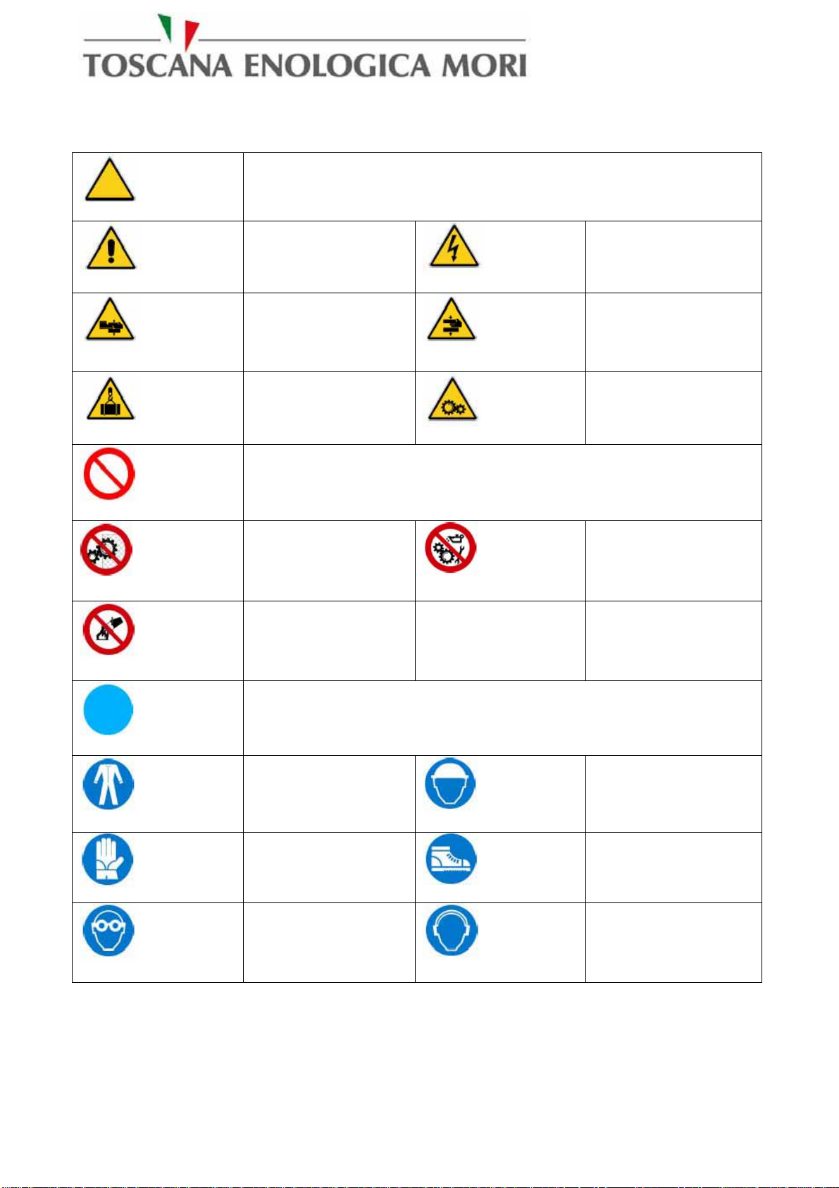
6.0 - Graphic symbols
DANGER SIGNS
GENERAL
DANGER DANGER OF
ELECTROCUTION
DANGER OF
CRUSHING DANGER OF
CRUSHING
OVERHEAD
LOAD WARNING
MOVING PARTS
WARNING
PROHIBITORY SIGNS
DO NOT
REMOVE
GUARDS
DO NOT
LUBRICATE
MOVING PARTS
DO NOT
EXTINGUISH
WITH WATER
MANDATORY SIGNS
WEAR
SUITABLE
CLOTHING SAFETY HELMET
MUST BE WORN
SAFETY GLOVES
MUST BE WORN
SAFETY BOOTS
MUST BE WORN
EYE
PROTECTION
MUST BE WORN
EAR
PROTECTION
MUST BE WORN

Operation manual OLIOMIO 350-500 FARM 9
7.0 – DATA PLATE AND NOTICES APPLIED
7.1 – Data plate
The machine is identified by a data plate made as required by Directive 98/37 CE,
placed in position A.
The electric panel is identified by a data plate made according to the requirements of Std. EN60204-
1 1998 ed. in a position not in view.
Figure 1 System plan view with data plate references
Figure 2 Data plate reference model

Operation manual OLIOMIO 350-500 FARM 10
WARNING
Never remove the data plate from its original position chosen by the manufacturer.
Do not alter or falsify the technical data specified.
Do not clean the plate with sharp objects (e.g.: metal brushes), to avoid effacing the data.
If the plate deteriorates with use or is no longer legible, even in only one of its points, you are
advised to ask the manufacturer for another one, stating the data contained in these instructions.
7.2– NOTICES PRESENT
DO NOT REMOVE GUARDS
WITHOUT FIRSTLY SWITCHING
OFF THE CURRENT
Figure 3 – Possible notices present on the machine
The Customer shall replace any data plate, pictogram or warning and danger signs if they are
effaced, worn, or in any case illegible.
Direction of rotation
Operation manual OLIOMIO 350-500 FARM 11
8.0 – Plant introduction and description
8.1 – Use and description
The machine has been designed and manufactured for a defined purpose and it may only be used for
the extraction of oil from olives.
Olives are crushed using the blade mill or even the pre-mill.
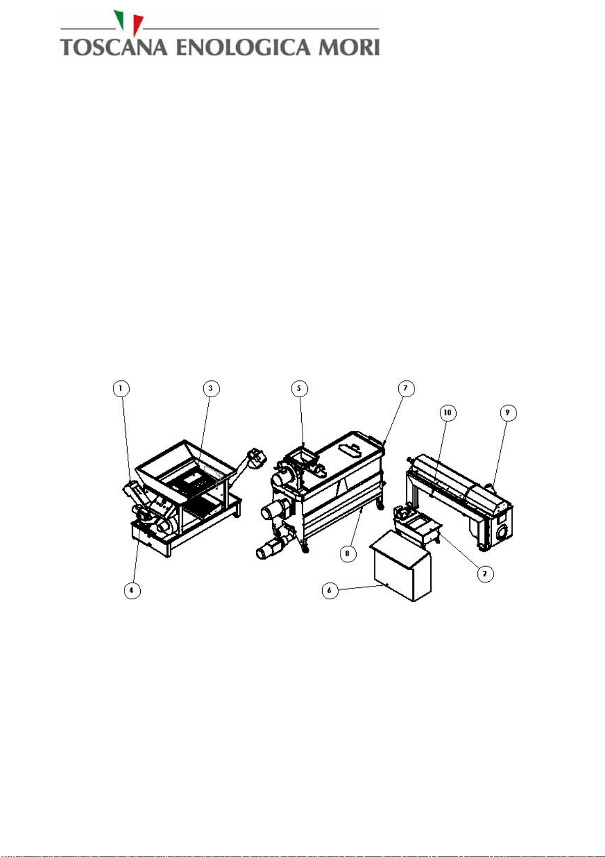
The plant is basically comprised of four modules, as detailed below:
•DLE-MAXI DLE Defoliating and washing machine; eliminates light matter (leaves and
twigs), heavy matter (stones and branches) and washes the olives with water.
•F2GL 350 – 500 Machine made up of two malaxation tanks for mixing the paste. They are
horizontal malaxation tanks.
•D350-D500 Decanter; separates the oil from water and pomace.
1- Leaves discharge
2- Oil recovery vat
3- Olives loading hopper
4- Variator on DLE olives feeding
5- Olives hopper to the Crusher
6- Main control board
7- Flow-meter
8- Variator on decanter paste feeding
9- Waste discharge
10-Oil outlet
Figure 1 – Plant description
After removal of the leaves and washing, olives reach the collection hopper where an auger driven
by a gear motor feeds the mill. The latter is equipped with a fixed grille with discharge ducts and a
hollow-blade impeller. The paste produced falls into the proper hopper where is prepared by
helicoidally shaped agitator. Once malaxation is completed, the paste is pumped into the decanter
where the oil is separated from the water and the waste. The pump placed at the oil outlet discharge
the waste material. All parts in touch with the product are made of AISI 304 Stainless Steel or food-
grade materials.

Operation manual OLIOMIO 350-500 FARM 12
8.2 – Illicit, improper or unauthorised use
The manufacturer declines any liability in the case of improper machine use, other than for the
purposes for which it has been designed and manufactured.
It is necessary to always carefully adhere to the rules of safety and to the instructions provided
herein. In particular, it is indispensable to comply with the operating limits stated in this handbook.
Unauthorised personnel must not be allowed near the equipment in use.
Use, maintenance and repairs are only allowed for suitably prepared and trained operators with their
own accident prevention equipment.
The manufacturer is also relieved of any liability in the case of:
•incorrect installation
•inadequate maintenance
•tampering
•use of non genuine spares
•failure to adhere to the indications provided
•exceptional events.
Use of the machine is forbidden:
•in places of public access;
•in environments with the risk of explosion or fire;
•in environments containing contaminants such as powders, acids, corrosive gases, etc.;
•in environments where the possibility exists of exposing it to radiations;
8.3 – The User company’s responsibility
The User company is responsible for ensuring that the persons appointed to the various tasks:
•possess the requirements listed below;
•read and understand the instructions for use and maintenance;
•receive suitable training for the tasks entrusted to them and are capable of performing them
under
safety conditions;
•receive specific training for correct use of the machine;
•have received appropriate individual protective devices.
•are in suitable physical and mental conditions (in any case not under the influence of
alcohol,
medicines or drugs).

Operation manual OLIOMIO 350-500 FARM 13
9.0 – Plant disassembly and assembly
WARNING:
Never start disassembly operations for any reason whatsoever before the machine has stopped
completely and the hot parts have cooled down. Make sure that the machine is not powered,
(remove the fuses or press the emergency button).
Place special notices to indicate that repair and/or maintenance work is in progress.
WARNING: For all other maintenance operations not mentioned in this handbook, it is
indispensable to contact an authorised TEM workshop.
9.1 – Equipment and safety systems used
1. Safety sensor on decanter opening
2. Emergency mushroom button on Electric Board
3. Emergency mushroom button on DLE.
4. Safety sensors on crusher opening
5. Safety sensor on mixer opening
6. Waste discharge vat
7. Identification plate with EC marking
8. Safety grill on the hopper with max. side opening 60 mm.
9. Safety grill on the hopper with max. side opening 60mm.
Figure 5 – Identification of safety systems used OPTIONAL (only on specific request):
1. Oil collection vat 2. plate or cotton filter

Operation manual OLIOMIO 350-500 FARM 14
10.0 – Operation and use
WARNING Before starting up the plant for the first time, make sure that the
cleaning operation has been carried out. For subsequent start ups, check that there is no
foreign matter or residues from previous processes inside the plant, otherwise clean it before
using.
WARNING Should the plant not be fitted with a washing unit, do not introduce in
the mill hopper a quality of product greater that 50 kg at a time. However, the hopper can
receive product continuously up to the plant’s maximum capacity.
10.1 – Preparation for use
Before use, make the following checks:
-Check for correct electrical connections, see paragraph 13.5.
-Check for correct water system connections , see paragraph 13.6.
-Check that the containers for the finished product are ready and in place.
-Check that the waste discharge device has been set up.
WARNING Pay attention to moving parts and augers. Do not insert foreign
matter, bulky, wooden or ferrous materials, or other.
WARNING During loading and unloading, it is absolutely forbidden to put the
hands or tools in the machine inlets and outlets.

Operation manual OLIOMIO 350-500 FARM 15
10.2 –Controls and start up devices
Figure 2 – Control board

Operation manual OLIOMIO 350-500 FARM 16
The following table describes the controls shown in the previous figure.
DESCRIPTION FUNCTION
1 NET ANALYZER VISUALIZES VOLT, AMPERE AND HERTZ DURING
PROCESS
2 BUTTON START
3 BUTTON EMERGENCY
4 MIXER 0-1 LIGHTING
SELECTOR ACTIVATES MIXER AGITATOR
17 LIGHTING SELECTOR
0-1 START SCREW OR WASTE DISCHARGE PUMP
18 LIGHTING SELECTOR
0-1 DECANTER START
19 RPM VISUALIZER VISUALIZE REVOLUTION OF DECANTER,
SCREW, CYLINDER AND DIFFERENTIAL RPM
20 KEYBOARD (optional) CRUSHER SPEED ADJUSTMENT
21 THERMAL REGULATOR REGULATION OF MIXERS TEMPERATURE AND
VISUALIZE MIXER TEMPERATURE 1-2-3-4
41 TWO POSITIONS
LIGHTING SELECTOR 0-
1 ACTIVATES OLIVES FEEDING TO THE CRUSHER
44 TWO POSITIONS
LIGHTING SELECTOR 0-1 CRUSHER ACTIVATION
52 LIGHTING PUSH BUTTON PASTE MANUAL TRANSFER
53 PUSH BUTTON STOPS PASTE TRANSFER
54 SELECTOR 0-1 MANUAL OR AUTOMATIC TRANSFER
55 LIGHTING SELECTOR
0-1-2 SPRING RECOVERY
1) ACTIVATES DECANTER FEELING OF MIXER IN
CASE THE DECANTER AND THE WASTE
DISCHARGE PUMP ARE WORKING
2) IT WORKS ALSO IF IT IS ALL OFF
Operation manual OLIOMIO 350-500 FARM 17
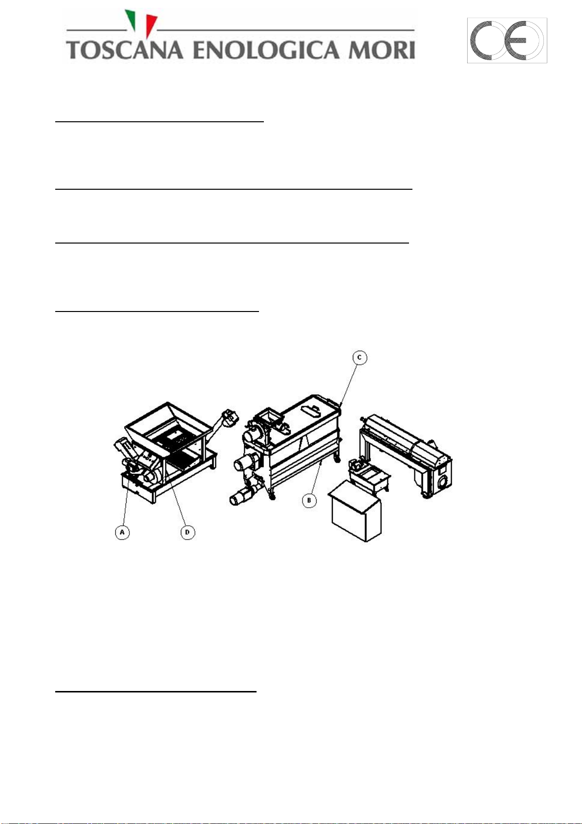
10.3 – Plant adjustments
OLIVE FEED SPEED ADJUSTMENT Olive feed speed to the mill can be adjusted using the
(A) hand wheel that acts on the DLE speed variator Rev. adjustment (1-9), when the Crusher
cannot drain off the olives, the hopper is full and you have to decrease the speed, in the opposite,
when the hopper is empty the speed has to be increased.
ADJUSTMENT OF PASTE INLET SPEED TO THE DECANTER Olive paste feed to the
decanter can be adjusted using the RPM regulation hand wheel (B) on the feeding pump moto-
variator pump (1-9).
ADJUSTMENT OF WATER ADDITION DURING EXTRACTION the paste going to the
decanter for the extraction can be diluted in order to obtain the proper oil extraction. This is possible
through the flow meter (C) fitted on the F2GL (0 - 100 litres) mill-malaxation unit; max
recommended flow 50 Lt.
ADJUSTMENT OF FAN ASPIRATION
Olives leaves aspiration can be adjusted opening the fan air recovery selvage (D), in case olives
going to the crusher contain a lot of leaves you have to open the air recovery selvage.
Figura 3 - Adjusments
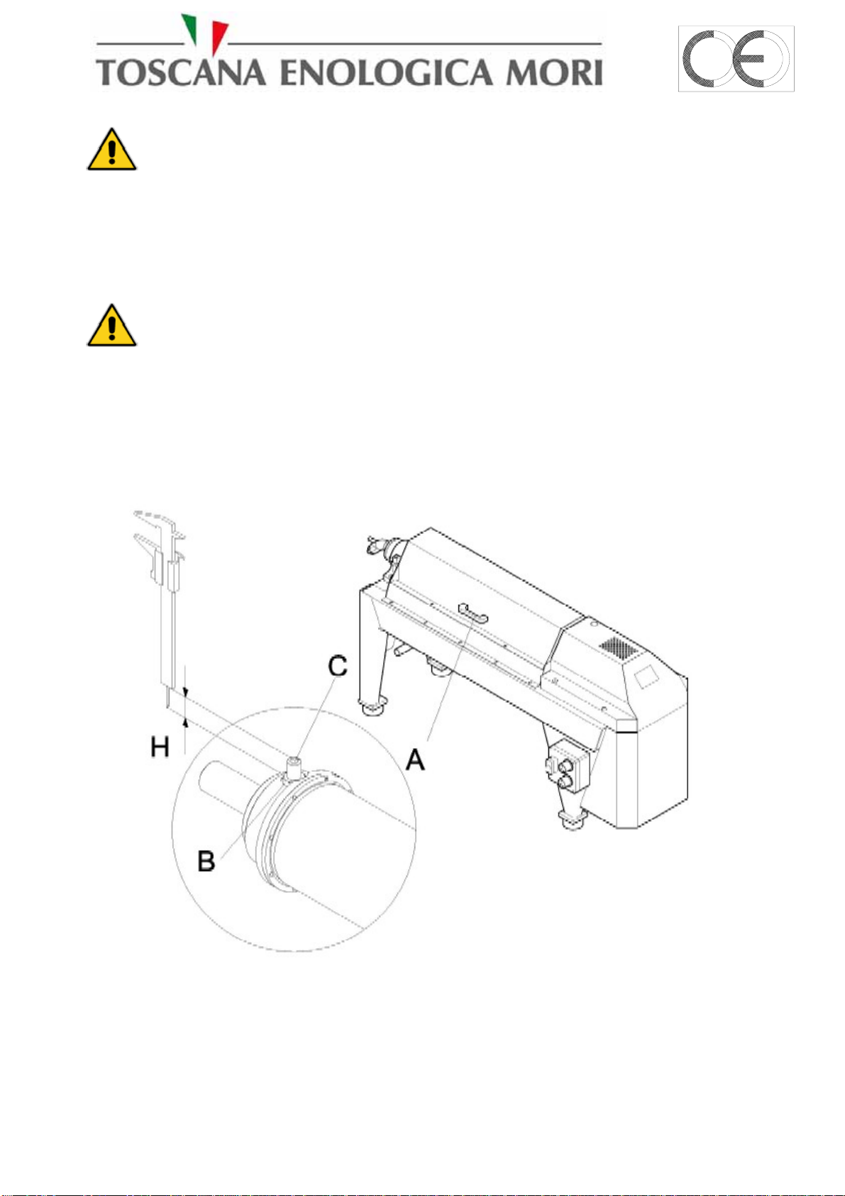
DECANTER NOZZLE ADJUSTMENT
a good oil extraction is when the oil is coming out opaque and without water particles, only if
your oil doesn’t have these characteristics you have to follow the below described indications to
replace the nozzles:
Operation manual OLIOMIO 350-500 FARM 18
WARNING This operation can be performed only after stopping the plant and with
the main switch set to the OFF position.
- the oil is too clear or too much water has been added (more than 100 lts), once the decanter is
stopped adjust the nozzles (1) taking them out of at least 1 mm.
- you already made the adjustments but the oil is still cloudy; adjust the nozzles taking them in
of 1 mm.
WARNING The nozzles must always be adjusted in pairs, never adjust them using
values differing from each other. Never assemble different kind of nozzles than those supplied by
the producer.
Figure 4 – Nozzle adjustment

Operation manual OLIOMIO 350-500 FARM 19
DLE WASHING WATER ADJUSTMENT
You have to regulate the flow entering the DLE so that the floating in the tank can keep the right
level, too much water entering the DLE can let it overflow on the floor.
OPTIONAL REGULATION AND CONTROL OF DECANTER DIFFERENTIAL
REVOLUTION (AUGER/CYLINDER) The instrument displays the differential speed between
the Decanter Screw and the Cylinder. Moreover it is possible to set the minimum differential value
below which paste inlet to the decanter is stopped. This prevents the decanter from clogging or
blocking.
-Pressing C1 you visualize screw speed.
-Pressing C2 you visualize cylinder speed.
Figure 5 – Adjustment interface example
IMPORTANT: We remind you that the machine is delivered with the minimum
differential value for PASTE INLET PUMP STOP set to “320”. Below this value the pump
stops. If you have to change this differential value, proceed as follows:
-Press C1 and C2 together for at least 5 seconds to display the menu:
IMPORTANT: This operation can be performed while the machines are operating.
The value set is immediately effective.
-Push C2; the first number on the right will flash, if you want to change it push C1.
-Push C1 and move to find the desired number.
-Push C2 to confirm the right value and automatically move to the next number, that will start to
flash, going on like this to the last number.
-When you finished push C1 several times till you will visualize EXIT, than C2 to confirm.
Verify that the value set has been registered pushing togheter C1+C2 for at least 5 seconds and
moving with C1 till you visualize Exit thank C2 to esc. .

Operation manual OLIOMIO 350-500 FARM 20
PASTE TEMPERATURE REGULATION The instrument detects the paste temperature
(Centigrade degrees); through the regulation you can increase or decrease the temperature or change
the value of SP parameter; to do this you have to enter to PROGRAM MODE, we remind you that
this value is usually reached after 1 hour of work.
IMPORTANT: The machine is delivered with SP regulated to “SP 025”.
if you want to program a different value, increase or decrease the paste temperature proceed as
follows:
-Push “P” ; flashing value “SP 025” will be visualized.
-Push upper or down arrows to change this value and set the desired one.
-Push “P” to confirm the value.
IMPORTANT: This regulation acts on the electric boiler for paste heating, on reaching of
the SP value set the boiler automatically stops; due to inductive factor and also because of the room
temperature, the paste temperature will increase of further 5°-6° C.
Figure 10 – Temperature display panel
Table of contents
Other Toscana Lawn And Garden Equipment manuals


