Toscana LINEAR GRAVITY FILLER Specification sheet

Instructions handbook 1
TECHNICAL LITERATURE
INSTRUCTIONS FOR USE AND MAINTENANCE
LINEAR GRAVITY FILLER
Manufacturer:
Toscana Enologica Mori S.n.c.
Via Cimabue 4-6 50028 Tavarnelle Val di Pesa (FI) Italy
C. F. / P. I.V.A. 01578280487
Tel. 055 8071568 - Fax 055 8071293
ΑΦΟΙ ΓΑΒΡΙΗΛΙΔΗ Α.Ε.Β.Ε.
Σταδίου 101, Τ.Κ. 59100 Βέροια
Τηλ.23310 20262 Fax 23310 20263
http://www.agroenos.com
Ηεταιρεία μας, ΑΦΟΙ ΓΑΒΡΙΗΛΙΔΗ Α.Ε.Β.Ε., ως επίσημος εισαγωγέας και
εξουσιοδοτημένος αντιπρόσωπος για όλη την Ελλάδα του ιταλικού
εργοστασίου Toscana Enologica Mori, παρέχει πλήρη τεχνική υποστήριξη
(service, συνεργείο, γνήσια ανταλλακτικά) και εγγύηση 2 ετών σε όλα τα
γεμιστικά φιαλών κρασιού Toscana Enologica Mori υπό την προϋπόθεση ότι
τηρούνται οι οδηγίες ορθής χρήσης και συντήρησης του γεμιστικού, όπως
ορίζονται από την κατασκευάστρια εταιρεία Toscana Enologica Mori.

Instructions handbook 2
LETTER AT DELIVERY
Kind customer,
We should like to inform you that the equipment referred to in this document has been designed,
manufactured and tested according to Italian law no. 459, dated 24th July 1996, which acknowledges the
European Directives concerning safety 89/392/EEC, 91/368/EEC, 93/44/EEC, 93/68/EEC and the
specifications of UNI EN Std. parts I and II and UNI EN 294.
With the handbook that follows our intention is to give a description of the sections that make it up, their
dimensional and technical specifications, the instructions for use and the maintenance procedures.
We are also including the certificate of Conformity as required by Directive 89/392 CE Annex II Part A.
We wish to confirm that the equipment presents no hazard for the operator, if used according to the
instructions provided, if incorporated in a machine which is, in turn, stated to be in conformity with directive
89/392 EEC and provided that:
⇒the guards installed are kept intact;
⇒the safety devices are kept in operating conditions;
⇒the specific operator instructions given herein are adhered to;
⇒the periodical maintenance operations are carried out and the components are checked as to their
state of wear and damage;
⇒the equipment is used within the foreseen operating parameters and with the machines for which
it has been designed and made;
While thanking you for your preference, we wish you profitable work.
Signature
The descriptions and illustrations herein are not to be considered binding.
The reproduction, even in part, and the divulgation of this document are not allowed without the express
permission of the author.
Any infringements will be prosecuted according to the Law.
All the names and brands mentioned herein belong to the respective Manufacturers.

Instructions handbook 3
INDEX
1.0 – FOREWORD.......................................................................................................................5
1.1 –IMPORTANCE OF THE HANDBOOK ..................................................................................5
1.2 -KEEPING THE HANDBOOK.................................................................................................5
1.3 -CONTENTS OF THE HANDBOOK........................................................................................5
1.4 –USE OF THE HANDBOOK ...................................................................................................5
1.5 –“CE” MARKING..................................................................................................................5
2.0 - REFERENCES.....................................................................................................................6
3.0 - GLOSSARY..........................................................................................................................6
4.0 - MACHINE IDENTIFICATION....................................................................................7
5.0 - GUARANTEE ......................................................................................................................7
6.0 - GRAPHIC SYMBOLS.....................................................................................................8
7.0 – DATA PLATE AND NOTICES APPLIED ...............................................................9
7.1 –DATA PLATE........................................................................................................................9
7.2 –NOTICES PRESENT...................................................................................................10
8.0 - MACHINE INTRODUCTION AND DESCRIPTION.........................................11
8.1 –USE AND DESCRIPTION..................................................................................................11
8.2 -ILLICIT,IMPROPER OR UNAUTHORISED USE .............................................................12
8.3 -THE USER COMPANY’S RESPONSIBILITY ....................................................................12
9.0 – MACHINE DISASSEMBLY AND ASSEMBLY ...................................................13
10.0 – OPERATION AND USE............................................................................................17
10.1 –VAT REGULATION .........................................................................................................17
10.2 –LEVEL ADJUSTMENT .....................................................................................................17
10.3 –STARTING AND STOPPING THE FILLER ....................................................................18
10.4 –USING THE MACHINE WITH OPTIONAL DEVICES ...................................................19
10.5 –TROUBLESHOOTING .....................................................................................................20
11.0 – SPECIFICATIONS.....................................................................................................22
11.1 –MODELS AVAILABLE.....................................................................................................22
12.0 - HANDLING AND DISPOSAL INSTRUCTIONS ............................................23
12.2 –DISPOSAL.......................................................................................................................23

Instructions handbook 4
13.0 - INSTALLATION AND WORKING ENVIRONMENT....................................25
13.1 -LIGHTING........................................................................................................................26
13.2 -NOISE ..............................................................................................................................26
13.3 -EXPLOSION OR FIRE HAZARD .....................................................................................26
13.4 -SPACE AND OBSTACLES................................................................................................27
13.5 -ELECTRICAL INSTALLATION ........................................................................................27
14.0 - INDIVIDUAL PROTECTIVE DEVICES .............................................................28
15.0 - MAINTENANCE ...........................................................................................................29
16.0 - SPECIFIC SAFETY INSTRUCTIONS.................................................................30
17.0 – SPARE PARTS.............................................................................................................31
17.1 –FILLER DRAWING .........................................................................................................32
DECLARATION OF CONFORMITY..........................................................................................33

Instructions handbook 5
1.0 – Foreword
The machine user shall inform personnel about the risks of accident, devices for operator safety,
risks of noise emission and about the general accident prevention rules set forth by international
directives and the laws in force.
Before starting the operating activities for which the machine is intended, the operator must be
perfectly informed about machine operation, the position of all the controls and the technical
characteristics and purpose of its use.
The machine may only be used by operators who have completely read and understood the
instructions contained herein.
Tampering/unauthorised replacement of parts of the machine, the use of non genuine spares and the
use of consumable materials that do not meet the specifications contained herein may represent a
serious accident hazard and relieve the manufacturer of civil and criminal liabilities.
1.1 – Importance of the handbook
1) Consider the instructions handbook as an integral part of the product
2) Keep the handbook throughout the whole life of the machine
3) Give the handbook to any other machine user
4) The wiring and pneumatic diagrams are enclosed herewith
1.2 - Keeping the handbook
1) Use the handbook in such a way as not to damage its contents either wholly or in part
2) Do not remove, tear or write on parts of the handbook for any reason whatsoever
3) Keep the handbook in a protected place
1.3 - Contents of the handbook
This handbook is defined by specific sections with indications and descriptions that can be traced
through the summary of the specific subjects.
1.4 – Use of the handbook
This handbook is an integral part of the supply.
Any alteration or change or integration to the machine without the manufacturer’s permission is
prohibited.
In the case of sale, hire, transfer for use or financial renting of the machine, the instructions must be
attached to it.
The technical specifications contained herein do not bind the manufacturer and may be changed on
future supplies with no prior notice.
Though it has been written with the utmost care, this handbook cannot entirely replace the
experience of the user, which must, therefore, be adequate for the operations to be performed.
The instructions contained herein do not replace, integrate or modify any of the standards, laws
and/or decrees in force in the place in which the equipment is used.
1.5 – “CE” marking
To guarantee that the equipment complies with the requirements of the Machine Directive
89/392/EEC and subsequent amendments, it has the CE plate as per Annex III of law 459/96.
Never remove the plate from its original position chosen by the manufacturer.
Do not alter or falsify the technical data it contains.
Do not clean the plate with sharp objects (e.g.: metal brushes), to avoid spoiling the above-
mentioned data.

Instructions handbook 6
If the plate deteriorates with use or is no longer legible, even in only one of its points, you are
advised to ask the manufacturer for another one, stating the data contained in these instructions.
If the declaration of conformity enclosed herewith is not present or has gone astray, it is possible to
ask our offices for a copy of it, stating the machine serial number given on the CE plate on the
machine.
2.0 - References
Manufacturer Toscana Enologica Mori S.n.c.. - via Cimabue n.4-6 50028
Tavarnelle Val di Pesa (FI)
Tel. 055 8071568 - Fax 055 8071293
Machine name LINEAR GRAVITY FILLER
Main reference standards
•Directive 98/37/CE approximation of the laws of member
states concerning machines
•Machines Directive 459/96 harmonising 89/392/EEC and
subsequent amendments,
•Directive 91/368/EEC, 93/68/EEC,
•Directive 89/336/EEC on “Electromagnetic Compatibility”
and law 615 dated 12/11/1996
•Directive 73/23/EEC on low voltage and bill of parliament
no. 791 dated 18/10/1977
•UNI EN 292/1, 292/2, 294, 349, 60204-1
Service Centre Solely c/o the manufacturer’s headquarters
Handbook MAY 2009
Review Rev.1
3.0 - Glossary
Hazardous areas Any area inside or in the vicinity of the machine in which the presence of an
exposed person is a hazard to the safety and health of that person.
Exposed person Any person wholly or partly inside a hazardous area.
Operator or worker The person or persons appointed to install, operate, adjust, carry out
maintenance operations, clean, repair or handle the machine.
Expert operator or skilled personnel In charge of set-up and start-up, lubrication, greasing,
routine and extraordinary maintenance, expressly authorised by the “Plant Manager”.
Electrical expert operator or skilled personnel In charge of set-up, start-up and maintenance of
the electrical section expressly authorised by the “Plant Safety Manager”.

Instructions handbook 7
4.0 - MACHINE IDENTIFICATION
Name Filling machine
Machine Linear filelr
Model B2, B3, B4, B6, Bd3 e Bd6
Serial Number Refer to Conformity Declaration
Year of construction Refer to Conformity Declaration
5.0 - GUARANTEE
The guarantee period is 24 months from the date of shipment (date of issue of shipping document).
During the guarantee period the transport expenses to our factory of parts, components and
machines covered by guarantee and re-delivery to destination are at the customer’s expense.
The guarantee does not include ordinary consumable materials like lubricants and materials needed
for cleaning, materials or parts subject to wear and those damaged due to incorrect machine
operation.
The manufacturer reserves to repair or replace parts proving to be faulty at its discretion.
TEM’s guarantee gives the customer the right to the replacement, in the shortest time possible, of
components or parts that prove to be faulty owing to poor quality or workmanship.
The guarantee ends 24 months from the time of shipment and any repairs, replacements or service
will be charged according to our current rates.
LIMITS OF GUARANTEE
The guarantee does not cover all the glass parts, knobs, fuses, trim parts and removable ones made
of plastic materials and also parts and components such as for example micro-switches, solenoid
valves, etc... The guarantee does not cover parts damaged by transport, faults caused by poor or
incorrect installation or maintenance, incorrect electrical or pneumatic supply, carelessness,
negligence or improper use, and in any case the failure to comply with the instructions given in the
handbook. This guarantee will not apply to defects caused by improper or inadequate
maintenance, or unauthorised alterations or use not in accordance with the specifications given for
the machine itself. The guarantee is invalidated in the case of alterations made on the machine
without the express permission of the manufacturer.
Tampering, unauthorised replacement of machine parts, the use of consumable materials other than
those foreseen and stated in the handbook, may be a source of danger of accident and relieve the
manufacturer of any civil and criminal liabilities.
The manufacturer is also not to be considered liable for any accidents that may arise to operators
resulting from manoeuvres not foreseen or advised against by this handbook.
The guarantee does not include compensation for damages or production stoppages.
N.B. No other guarantee is expressed or implicit.

Instructions handbook 8
6.0 - Graphic symbols
DANGER SIGNS
GENERAL DANGER
DANGER OF
ELECTROCUTION
DANGER OF
CRUSHING
DANGER OF
CRUSHING
OVERHEAD LOAD
WARNING
MOVING PARTS
WARNING
PROHIBITORY SIGNS
DO NOT REMOVE
GUARDS
DO NOT
LUBRICATE
MOVING PARTS
DO NOT
EXTINGUISH WITH
WATER
MANDATORY SIGNS
WEAR SUITABLE
CLOTHING
SAFETY HELMET
MUST BE WORN
SAFETY GLOVES
MUST BE WORN
SAFETY BOOTS
MUST BE WORN
EYE PROTECTION
MUST BE WORN
EAR PROTECTION
MUST BE WORN

Instructions handbook 9
7.0 – DATA PLATE AND NOTICES APPLIED
7.1 – Data plate
The machine is identified by a data plate made as required by Directive 98/37 CE, placed in
position A.
Figura 1 Vista della macchina con riferimenti targhette
Figure 2 - Data plate reference model
WARNING
Never remove the data plate from its original position chosen by the manufacturer.
Do not alter or falsify the technical data specified. Do not clean the plate with sharp objects (e.g.:
metal brushes), to avoid effacing the data. If the plate deteriorates with use or is no longer legible,
even in only one of its points, you are advised to ask the manufacturer for another one, stating the
data contained in these instructions.
MACHINE
MODEL
VOLTAGE
MODEL
YEAR OF MANUFACTURE
SERIAL No.

Instructions handbook 10
7.2 – NOTICES PRESENT
Figure 3 – Possible notices present on the machine
The Customer shall replace any data plate, pictogram or warning and danger signs if they are
effaced, worn, or in any case illegible.
Direction of rotation
DO NOT REMOVE
GUARDS WITHOUT
FIRSTLY SWITCHING
OFF THE CURRENT

Instructions handbook 11
8.0 - Machine introduction and description
8.1 – Use and description
Filling machine B have been realized to suite the needs of small producers; the machine is suitable
for filling of glass bottles with wine, oil, cosmetics, milk, bear and fruit juices. Main parts of the
filling machine are:
-tank (A) with main frame in AISI 304 STAINLESS STEEL,
-series of filling nozzles (B) to facilitate insertion and ejection of the bottles,
-self-priming pump (D), Coaxial pump with natural, non toxic rubber impeller, Neoprene,
Nitril, EPDM or silicon; both types of pump can be supplied with By-Pass,
-electric floater (E) (OPTIONAL) or mechanical floater (C) (OPTIONAL),
-cartridge (F) for microfiltration (OPTIONAL).
-saturator (G) for addition of gas in the product (OPTIONAL).
1. Cover
2. Inlet pipe
3. Vat discharge valve
4. Drops recovery vat
5. Tank level
6. Total tank discharge valve.
7. Bottle to fill
8. Holes for regulation of vat
height
9. Filler inlet valve
10. Panel control (available on
models with electric floater).
Figure 4 – Linear filler description

Instructions handbook 12
8.2 - Illicit, improper or unauthorised use
The manufacturer declines any liability in the case of improper machine use, other than for the
purposes for which it has been designed and manufactured.
It is necessary to always carefully adhere to the rules of safety and to the instructions provided
herein. In particular, it is indispensable to comply with the operating limits stated in this handbook.
Unauthorised personnel must not be allowed near the equipment in use.
Use, maintenance and repairs are only allowed for suitably prepared and trained operators with their
own accident prevention equipment.
The manufacturer is also relieved of any liability in the case of:
•incorrect installation
•inadequate maintenance
•tampering
•use of non genuine spares
•failure to adhere to the indications provided
•exceptional events.
Use of the machine is prohibited:
•in places of public access;
•in environments with the risk of explosion or fire;
•in environments containing contaminants such as powders, acids, corrosive gases, etc.;
•in environments where the possibility exists of exposing it to radiations;
8.3 - The User company’s responsibility
The User company is responsible for ensuring that the persons appointed to the various tasks:
•possess the requirements listed below;
•read and understand the instructions for use and maintenance;
•receive suitable training for the tasks entrusted to them and are capable of performing them
under safety conditions;
•receive specific training for correct use of the machine;
•have received appropriate individual protective devices.
•are in suitable physical and mental conditions (in any case not under the influence of alcohol,
medicines or drugs).

Instructions handbook 13
9.0 – Machine disassembly and assembly
WARNING:
Never start disassembly operations for any reason whatsoever before the machine has stopped
completely and the hot parts have cooled down. Make sure that the machine is not powered,
(remove the fuses or press the emergency button). Place special notices to indicate that repair and/or
maintenance work is in progress.
WARNING:
For all other maintenance operations not mentioned in this handbook, it is indispensable to contact
an authorised TEM workshop.
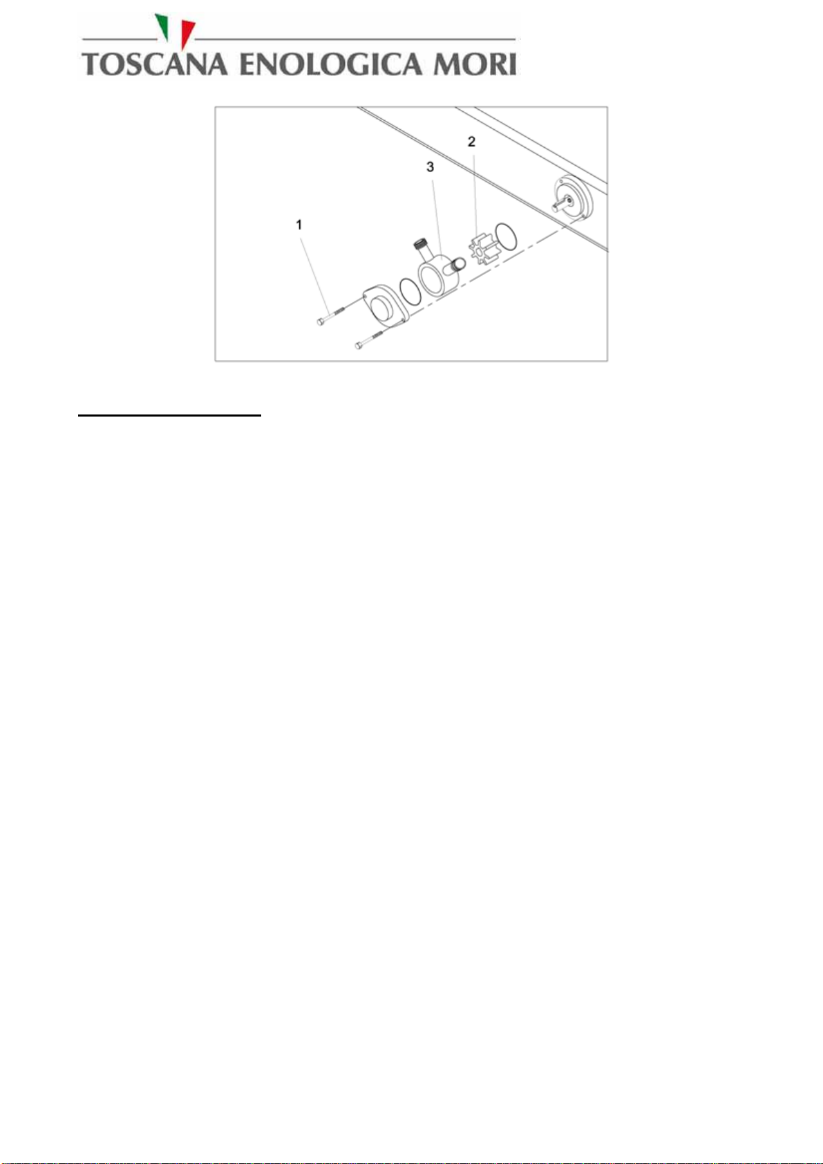
DISMANTLING PUMP BODY
•Loose the screws (1) on the pump body
•Clean the impeller (2) and the inner part of the pump body (3).
•Put inside the pump body and fix the screws.
Figure 5 – Dismantling the pump: centrifugal electro-pump
Instructions handbook 14
Figure 6 - Self-priming pump
VALVE DISMANTLING
Follow the below indications to replace the seals of the filling valves or to clean them.:
•While the machine is stopped and completely empty:
1- Loosen the screws and the nut (B), free the clamp (C), in this way all the filling valve
(A) can be removed from the machine.
2 – Unscrew the regulation ring-nut and the cone connected to it (7 e 8).
3 – Unscrew the small ring on the cone (6) using the pliers.
4 – Unscrew the lower sliding guide (11) keeping stopped with pliers the external rod
(10) remaining nearby the side that has higher diameter.
5- It is possible to act on the seal gasket (12).
6 – Extract the fix side (1) and the spring (13) along the upper spring-guide (5).
•Replace the desired gaskets and/or clean the filling nozzle and grease.
For a proper clearing of the filling nozzle blow compressed air into the holes (PRODUCT) and
(AIR).

Instructions handbook 15
If need be you can replace the followings:
Figure 7 – valve dismantling details
REINSTATEMENT OF THERMIC SWITCH AND FUSE
Before going on with the reinstatement of thermic switch and/or fuse, be sure that the machine is
electrically disconnected and proceed as follows:
•Open the electric board of the machine
•Reactivate the thermic switch (1) moving it to ON and/or replace the fuse (2).
•Close the control board

Instructions handbook 16
Figure 8 – Reinstatement of thermic switch and fuse
CONNECTION DIAGRAM:
Figure 9 – Connection product-filler

Instructions handbook 17
10.0 – Operation and use
WARNING
Before starting the machine for the first time make sure that the cleaning, lubricating and
maintenance operations have been carried out.
-Connect the plug f the control board to the power supply net,
-Connect the machine piping to the product tank,
-Adjust the vat position accordingly to the kind of bottle used (ref.to chapter 10.3).
-Adjust the level of liquid into the bottle as per chapter 10.3.
10.1 – Vat regulation
You can regulate the vat height accordingly to
the bottles height and to the filling level
required: Move the vat up removing it from
the holes and place it up or down. Incline the
vat upward removing it out from the holes
sliding it up or down as required, than put it
back in position inside the proper holes on the
lateral side (look at the picture).
ATTENTION: Be sure that the
vat is re-aligned correctly.
Figure 10 – Vat regulation
10.2 – Level adjustment
In order to find the right level of product into
the bottle act as follows:
•Screw or unscrew the ring-nut (A) to
obtain the desired level into the bottles.
•We remind you that screwing
ANTICLOCKWISE the ring-nut the
level will be lower, screwing
CLOCKWISE the level will be higher.
•We recommend to act on the ring-nut
with a minimum number of REV. to
avoid liquid overflowing.
Figure 11 – Level adjustment

Instructions handbook 18
ATTENTION: the ring-nut has always to be adjusted without the bottle placed under it.
10.3 – Starting and stopping the filler
STARTING THE FILLER
After you made the above mentioned operations
proceed as follows:
•open valve (A),
•remove cap (H) and fulfil with product the
pump body, than close it,
•for the machines without electric board
move the PUMP switch (B) TO “ON” and
control that the light is on, for the models
without the panel board the flashing light is
placed on the pump,
•for the machines with electric panel activate
the green push button (START or 1) after
having risen the emergency button to turn on
the machine.
•IMPORTANT: verify the sense of rotation
looking at the side that is sucking,
•rotate the filling valve ahead (C) and insert it
into the bottle, than place it on the vat (D),
•proceed to discharge the fulfilled bottles and
to load the empty ones,
•always control the filling level (E) of the
tank especially for the models without the
floating valve,
•the filling valves of the filler can let drip
some drop of product inside the vat, that can
be emptied through the proper valve (F).
Figure 12 – Functioning commands
ATTENTION: If after some second after switching on of the machine the pump is not
priming control the connections of piping and fittings to verify that there are no air seepage.
STOPPING THE FILLER
To stop the machine proceed as follows:
•Move PUMP switch to “OFF” or push the STOP key for the machines with EXTERNAL
BOARD
•continue to bottle till the tank is completely empty, or discharge the tank through the proper
valve (G) for the total discharge,
For the filler washing refer to the following indications:
•fulfil the tank with the desired washing product,
•carry out the different filling phases for each filling valve.
We suggest you to carry out the washing phase first with water, than with specific products.

Instructions handbook 19
FILLER WORKING CONTROL
When the filling machine is in operation it is require the tank level control to the operator,
especially in the models without floating device, if the level of the product in tank is going too
down you can act on the by-pass valve (Z), opening the valve the pump is sucking less quantity of
product and closing it it is sucking more.
10.4 – Using the machine with optional devices
USE OF THE FILLER WITH SATURATOR
The machine equipped with saturator, that can
also be installed in a second time, do not
require any particular shrewdness, but only
the connection that has to be made as follows:
Connect the gas cylinder pipe with pre-
heating element to valve (A) on the saturator,
•Open the valve of the gas cylinder and
regulate the pressure between 0,2 and
2,5 Bar, accordingly to the product
needs.
ATTENTION: It is very important that
the product to gas has a temperature not
higher than 5°C.
Figure 13 – Saturator
USE OF THE FILLER WITH STERILIZATION CARTRIDGE
The machine equipped with sterilization
cartridge do not need any particular care as it
is placed in line on the product enter. It is
only necessary to take care of the cartridge
maintenance that has to be removed at the end
of the working cycle and kept into a solution
of water with Peracetric acid at 1%.
Figure 14 – Dismantling the cartridge

Instructions handbook 20
10.5 – Troubleshooting
In the event of operating faults, it is wise to stop the machine and carry out the procedures listed in
the table below.
WARNING:
Before doing any maintenance work, make sure that the electric plug is disconnected.
SYMPTOM CAUSE MEASURE
There is air into the circuit
A) Verify that the pipe connections
are right.
B) Carry out a new pump priming .
THE PUMP CANNOT
REACH THE RIGHT
PRESSURE
The pump impeller is dirty
Disassemble the casing of the pump
body and clean both the impeller and
the inner part of the body pump ref. to
chapter 9
PRODUCT DRIPPING
FROM THE NOZZLES worn gaskets Replace the worn gaskets
VALVES ARE NOT
SMOOTH RUNNING OR
BLOCKED
Valves not enough
lubricated
Pull up the spring on the valve and
pour proper Vaseline grease on the
central rod of the nozzle.
VALVES ARE NOT
DELIVERING THE
PRODUCT OR ONLY IN
IRREGULAR MODE
The air recovery ducts are
dirty or blocked Clean with compressed air
Jumping of the thermic
switch or fuse (only for
the models with electric
board built in with the
machine)
Restore the thermic and/or replace the
fuse
THE PUMP IS NOT
STARTING
Electric circuit interrupted
Restore the electric connection
Table of contents
Other Toscana Lawn And Garden Equipment manuals


Popular Lawn And Garden Equipment manuals by other brands


Kress Robotik
Kress Robotik MISSION KR120E owner's manual

Factoryfurniture
Factoryfurniture SCROLL Operation & maintenance manual

Handy Home Products
Handy Home Products VALUE Series Assembly manual

Pyle
Pyle SereneLife PSLBZ8 user manual

Oase
Oase InScenio FM-Master 1 operating instructions

Craftsman
Craftsman 358.797110 Operator's manual

Radarcan
Radarcan R-105 user guide

Trac Vac
Trac Vac 865 Operating and assembly manual

The Kelly Company
The Kelly Company ICS955 instruction manual

Stiga
Stiga SD 98 Series Operator's manual

Ardisam
Ardisam GARDEN STAR 5020D Service, troubleshooting, and repair manual

Gardena
Gardena EVC 1000 operating instructions