Toscana MINI DLE Specification sheet

MINI DLE Instructions Handbook
1
TECHNICAL LITERATURE
INSTRUCTIONS FOR USE AND MAINTENANCE
MINI DLE and FOLAVENTO
Manufacturer:
Toscana Enologica Mori S.n.c.
50028 Tavarnelle Val di Pesa (FI) Italy
C. F. / P. I.V.A. 01578280487
Tel. 055 8071568 - Fax 055 8071293
ΑΦΟΙ ΓΑΒΡΙΗΛΙΔΗ Α.Ε.Β.Ε.
Σταδίου 101, Τ.Κ. 59100 Βέροια
Τηλ.23310 20262 Fax 23310 20263
http://www.agroenos.com
Ηεταιρεία μας, ΑΦΟΙ ΓΑΒΡΙΗΛΙΔΗ Α.Ε.Β.Ε., ως επίσημος εισαγωγέας
και εξουσιοδοτημένος αντιπρόσωπος για όλη την Ελλάδα του ιταλικού
εργοστασίου Toscana Enologica Mori, παρέχει πλήρη τεχνική υποστήριξη
(service, συνεργείο, γνήσια ανταλλακτικά) και εγγύηση 2 ετών σε όλα τα
συγκροτήματα πλύσης ελιάς Toscana Enologica Mori υπό την προϋπόθεση
ότι τηρούνται οι οδηγίες ορθής χρήσης και συντήρησης του μηχανήματος,
όπως ορίζονται από την κατασκευάστρια εταιρεία Toscana Enologica Mori.
MINI DLE Instructions Handbook
2
LETTER AT DELIVERY
Kind customer,
We should like to inform you that the equipment referred to in this document has been designed,
manufactured and tested according to Italian law no. 459, dated 24th July 1996, which acknowledges the
European Directives concerning safety 89/392/EEC, 91/368/EEC, 93/44/EEC, 93/68/EEC and the
specifications of UNI EN Std. section I and II and UNI EN 294.
With the handbook that follows our intention is to give a description of the sections that make it up, their
dimensional and technical specifications, the instructions for use and the maintenance procedures.
We are also including the certificate of Conformity as required by Directive 89/392 CE Annex II Section A.
We wish to confirm that the equipment presents no hazard for the operator, if used according to the
instructions provided, if incorporated in a machine which is, in turn, stated to be in conformity with directive
89/392 EEC and provided that:
- the guards installed are kept intact;
- the safety devices are kept in operating conditions;
- the specific operator instructions given herein are adhered to;
- the periodical maintenance operations are carried out and the components are checked as to their
state of wear and damage;
- the equipment is used within the foreseen operating parameters and with the machines for which it
has been designed and made;
While thanking you for your preference, we wish you profitable work.
Signature
The descriptions and illustrations herein are not to be considered binding.
The reproduction, even in part, and the divulgation of this document are not allowed without the express
permission of the author.
Any infringements will be prosecuted according to the Law.
All the names and brands mentioned herein belong to the respective Manufacturers.

MINI DLE Instructions Handbook
3
LIST OF CONTENTS
1.0 FOREWORD……..………………………..………………………………….……………………………….…….5
1.1 IMPORTANCE OF THE HANDBOOK……………………..………………………………..………..……..5
1.2 KEEPING THE HANDBOOK………..……………………………………………………………………….……5
1.3 CONTENTS OF THE HANDBOOK……………..………………………………………………..…..….…..5
1.4 USE OF THE HANDBOOK……….……………………………………………..………..………………………5
1.5 “CE” MARKING………..………………………………………………………………………………….…………..5
2.0 REFERENCES……...……………………………………………………………………………………………..…6
3.0 GLOSSARY……………………………...…………………………………………………….....................6
4.0 MACHINE IDENTIFICATION……..…………………………………………………………..…….…..7
5.0 GUARANTEE…..……………………………………………………………………………….……….…….…...7
6.0 GRAPHIC SYMBOLS………………..…………………………………………………………………………..8
7.0 DATA PLATE AND NOTICES APPLIED…..……………………………….......................9
7.1 DATA PLATE……..…………………………………….……………………………………………………………...9
7.2 NOTICES PRESENT……………..………………….…………………………………………………..……….10
8.0 MACHINE INTRODUCTION AND DESCRIPTION………….……………………………….11
8.1 USE AND DESCRIPTION……...………………………………………..…………………………………...11
8.2 ILLICIT, IMPROPER OR UNAUTHORISED USE……………………………….….………………..12
8.3 THE USER COMPANY’S RESPONSIBILITY…………………………………………………………….12
9.0 PLANT DISASSEMBLY AND ASSEMBLY……..……………………………………………….…13
9.1 EQUIPMENT AND SAFETY SYSTEMS USED.………………………………………………………...13
10.0 OPERATION AND USE………………………………………………………..……………………………..14
10.1 PREPARATION FOR USE…………………………….……………………………………………….……..…14
10.2 CONTROL AND START UP DEVICE…………………………………………………………….…..…...15
10.3 PLANT ADJUSTMENTS……………………………………………………………………………….……….…17
10.4 STARTING AND STOPPING THE PLANT……………………………….……………………………...17
10.5 OPERATION CONTROLLING…………………………………………………...…………………………...17
10.6 TROUBLESHOOTING……………………………………………………………………………………..……..18
11.0 SPECIFICATIONS..………………………………………………………………………………….….….…19

MINI DLE Instructions Handbook
4
11.1 MINI DLE……………..………………………………..……….…………………………..……………………....19
12. HANDLING AND DISPOSAL INSTRUCTIONS……………………………………………......20
12.1 PACKING…………..……..………………………………………………………………………….…………….….20
12.2 DISPOSAL……...………..……………………………………………………………………………………..…..20
13. INSTALLATION AND WORKING ENVIRONMENT………………………….……..……..…22
13.1 LIGHTING…………………………………..…..…………………………………………………………….….….22
13.2 NOISE……………..…………………………………………………………………………………….……….…....23
13.3 EXPLOSION OR FIRE HAZARD..……………………………………………………………………..…….23
13.4 SPACE AND OBSTACLES…………………………………………………………………………………......23
13.5 ELECTRICAL INSTALLATION.………………….……………………………………………………..…....23
13.6 WATER SYSTEM…….……………..………………….………………………………………………………....24
14. INDIVIDUAL PROTECTIVE DEVICES………………………….………………………..…..…25
15. MAINTENANCE…….…………...………………………………………..………….…………………….......26
16. SPECIFIC SAFETY INSTRUCTIONS…………….……………….……………………………..…….28
17. SPARE PARTS…………………………………………..……………………………………………………...…..29
17.1 MINI DLE SPARE PARTS…..………………………..………………………….……………………….…...30
DECLARATION OF CONFORMITY…………………………………………….……………………...………32

MINI DLE Instructions Handbook
5
1.0 – Foreword
The machine user shall inform personnel about the risks of accident, devices for operator safety,
risks of noise emission and about the general accident prevention rules set forth by international
directives and the laws in force. Before starting the operating activities for which the machine is
intended, the operator must be perfectly informed about machine operation, the position of all the
controls and the technical characteristics and purpose of its use. The machine may only be used by
operators who have completely read and understood the instructions contained herein.
Tampering/unauthorised replacement of parts of the machine, the use of non genuine spares and the
use of consumable materials that do not meet the specifications contained herein may represent a
serious accident hazard and relieve the manufacturer of civil and criminal liabilities.
1.1 – Importance of the handbook
1) Consider the instructions handbook as an integral part of the product
2) Keep the handbook throughout the whole life of the machine
3) Give the handbook to any other machine user
4) The wiring and pneumatic diagrams are enclosed herewith
1.2 – Keeping the handbook
1) Use the handbook in such a way as not to damage its contents either wholly or in part
2) Do not remove, tear or write on parts of the handbook for any reason whatsoever
3) Keep the handbook in a protected place
1.3 – Contents of the handbook
This handbook is defined by specific sections with indications and descriptions that can be traced
through the summary of the specific subjects.
1.4 – Use of the handbook
This handbook is an integral part of the supply. Any alteration or change or integration to the
machine without the manufacturer’s permission is prohibited. In the case of sale, hire, transfer for
use or financial renting of the machine, the instructions must be attached to it. The technical
specifications contained herein do not bind the manufacturer and may be changed on future supplies
with no prior notice. Though it has been written with the utmost care, this handbook cannot entirely
replace the experience of the user, which must, therefore, be adequate for the operations to be
performed. The instructions contained herein do not replace, integrate or modify any of the
standards, laws and/or decrees in force in the place in which the equipment is used.
1.5 – “CE” marking
To guarantee that the equipment complies with the requirements of the Machine Directive
89/392/EEC and subsequent amendments, it has the CE plate as per Annex III of law 459/96.
Never remove the plate from its original position chosen by the manufacturer.
Do not alter or falsify the technical data it contains. Do not clean the plate with sharp objects
(e.g.:metal brushes), to avoid spoiling the above-mentioned data. If the plate deteriorates with use or
is no longer legible, even in only one of its points, you are advised to ask the manufacturer for
MINI DLE Instructions Handbook
6
another one, stating the data contained in these instructions.
If the declaration of conformity enclosed herewith is not present or has gone astray, it is possible to
ask our offices for a copy of it, stating the machine serial number given on the CE plate on the
machine.
2.0 - References
Manufacturer Toscana Enologica Mori S.n.c. 50028 Tavarnelle Val di Pesa
(FI) Tel. 055 8071568 - Fax 055 8071293
Machine name MINI DLE unit (leaf remover + washer +lift)
Main reference standards
•Directive 98/37/CE approximation of the laws of member
states concerning machines • Machines Directive 459/96
harmonising 89/392/EEC and subsequent amendments, •
Directive 91/368/EEC, 93/68/EEC, • Directive 89/336/EEC on
“Electromagnetic Compatibility” and law 615 dated
12/11/1996 • Directive 73/23/EEC on low voltage and bill of
parliament no. 791 dated 18/10/1977 •UNI EN 292/1, 292/2,
294, 349, 60204-1
Service Centre Solely c/o the manufacturer’s headquarters
Handbook 2006
Review Rev.1
3.0 - Glossary
Hazardous areas Any area inside or in the vicinity of the machine in which the presence of an
exposed person is a hazard to the safety and health of that person.
Exposed person Any person wholly or partly inside a hazardous area.
Operator or worker The person or persons appointed to install, operate, adjust, carry out
maintenance operations, clean, repair or handle the machine.
Expert operator or skilled personnel In charge of set-up and start-up, lubrication, greasing,
routine and extraordinary maintenance, expressly authorised by the “Plant Manager”.
Electrical expert operator or skilled personnel In charge of set-up, start-up and maintenance of
the electrical section expressly authorised by the “Plant Safety Manager” .

MINI DLE Instructions Handbook
7
4.0 – MACHINE IDENTIFICATION
Name LEAF REMOVER+WASHER+LIFT
Machine MINI DLE
Model MINI DLE
Serial no. See Declaration of Conformity
Year of manufacture See Declaration of Conformity
5.0 - GUARANTEE
The guarantee period is 24 months from the date of shipment (date of issue of shipping document).
During the guarantee period the transport expenses to our factory of parts, components and
machines covered by guarantee and re-delivery to destination are at the customer’s expense.
The guarantee does not include ordinary consumable materials like lubricants and materials needed
for cleaning, materials or parts subject to wear and those damaged due to incorrect machine
operation.
The manufacturer reserves to repair or replace parts proving to be faulty at its discretion.
TEM’s guarantee gives the customer the right to the replacement, in the shortest time possible, of
components or parts that prove to be faulty owing to poor quality or workmanship.
The guarantee ends 24 months from the time of shipment and any repairs, replacements or service
will be charged according to our current rates.
LIMITS OF GUARANTEE
The guarantee does not cover all the glass parts, knobs, fuses, trim parts and removable ones made
of plastic materials and also parts and components such as for example micro-switches, solenoid
valves, etc... The guarantee does not cover parts damaged by transport, faults caused by poor or
incorrect installation or maintenance, incorrect electrical or pneumatic supply, carelessness,
negligence or improper use, and in any case the failure to comply with the instructions given in the
handbook. This guarantee will not apply to defects caused by improper or inadequate maintenance,
or unauthorised alterations or use not in accordance with the specifications given for the machine
itself. The guarantee is invalidated in the case of alterations made on the machine without the
express permission of the manufacturer. Tampering, unauthorised replacement of machine parts, the
use of consumable materials other than those foreseen and stated in the handbook, may be a source
of danger of accident and relieve the manufacturer of any civil and criminal liabilities. The
manufacturer is also not to be considered liable for any accidents that may arise to operators
resulting from manoeuvres not foreseen or advised against by this handbook. The guarantee does
not include compensation for damages or production stoppages.
N.B. No other guarantee is expressed or implicit.
MINI DLE Instructions Handbook
8
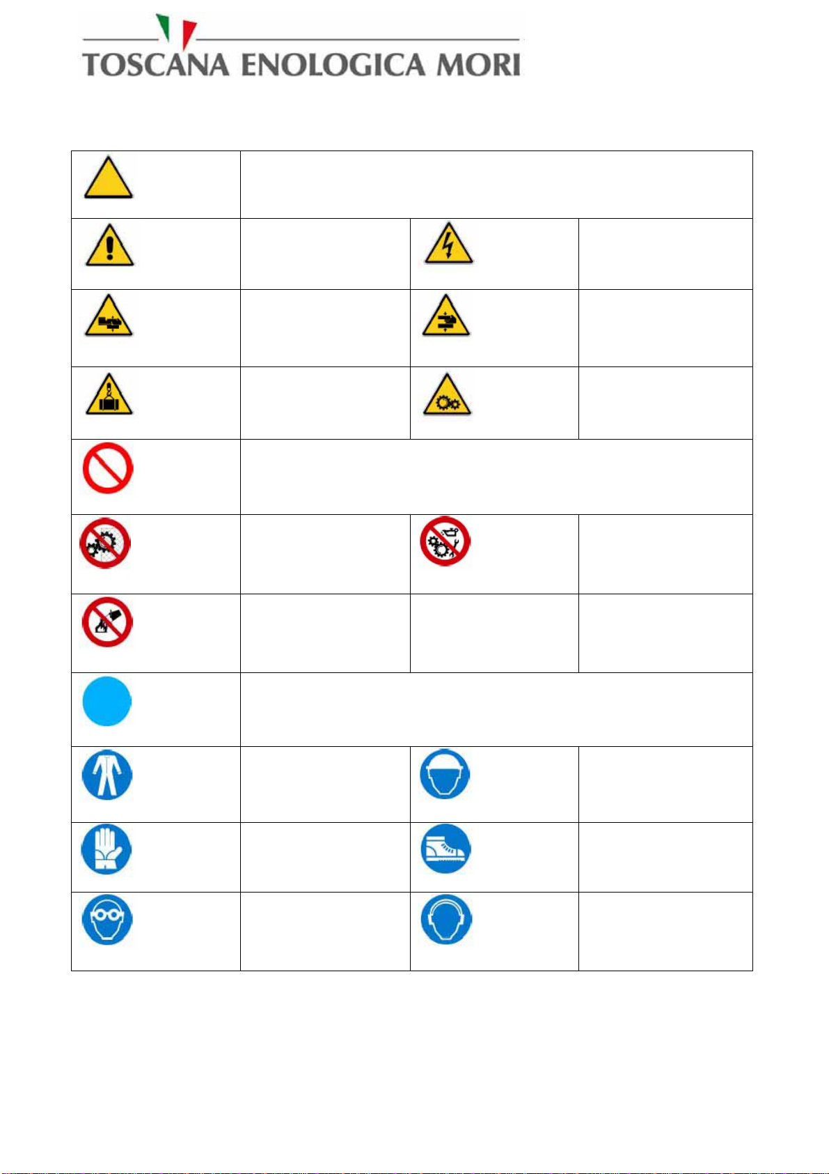
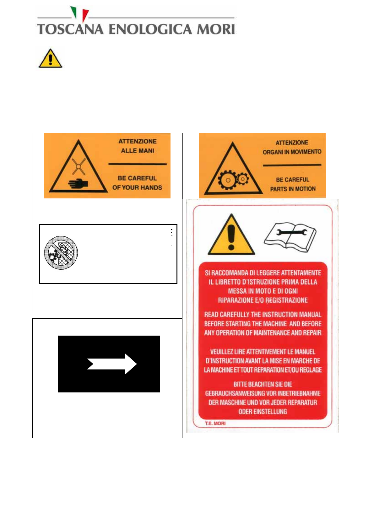
6.0 - Graphic symbols
DANGER SIGNS
GENERAL
DANGER DANGER OF
ELECTROCUTION
DANGER OF
CRUSHING DANGER OF
CRUSHING
OVERHEAD
LOAD WARNING
MOVING PARTS
WARNING
PROHIBITORY SIGNS
DO NOT
REMOVE
GUARDS
DO NOT
LUBRICATE
MOVING PARTS
DO NOT
EXTINGUISH
WITH WATER
MANDATORY SIGNS
WEAR
SUITABLE
CLOTHING SAFETY HELMET
MUST BE WORN
SAFETY GLOVES
MUST BE WORN
SAFETY BOOTS
MUST BE WORN
EYE
PROTECTION
MUST BE WORN
EAR
PROTECTION
MUST BE WORN
MINI DLE Instructions Handbook
9
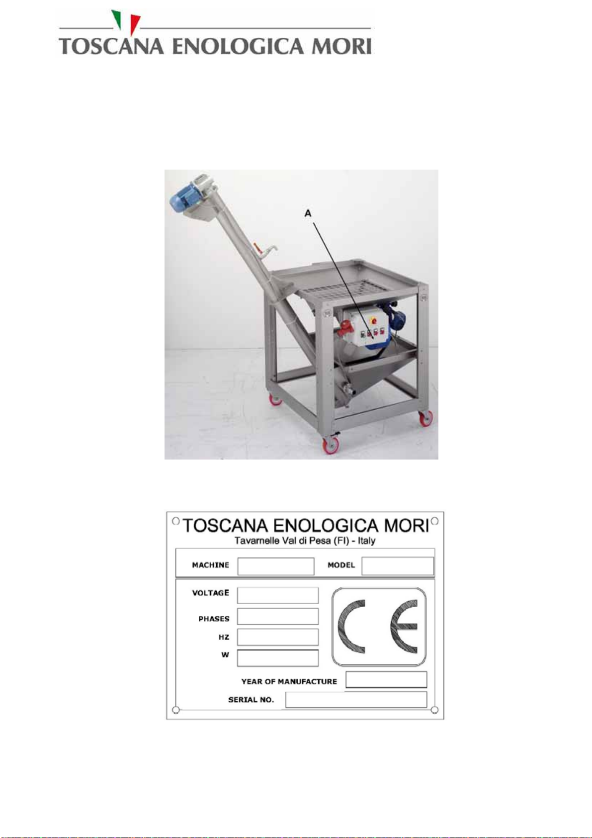
7.0 – DATA PLATE AND NOTICES APPLIED
7.1 – Data plate
The machine is identified by a data plate made as required by Directive 98/37 CE, placed in
position A.
The electric panel is identified by a data plate made according to the requirements of Std.
EN60204-1 1998 ed. in a position not in view.
.
Figure 1 System plan view with data plate references
Figure 2 Data plate reference model
MINI DLE Instructions Handbook
10
WARNING
Never remove the data plate from its original position chosen by the manufacturer. Do not alter or falsify the
technical data specified. Do not clean the plate with sharp objects (e.g.: metal brushes), to avoid effacing the
data. If the plate deteriorates with use or is no longer legible, even in only one of its points, you are advised
to ask the manufacturer for another one, stating the data contained in these instructions.
7.2 – NOTICES PRESENT
Direction of rotation
Figure 3 – Possible notices present on the machine
The Customer shall replace any data plate, pictogram or warning and danger signs if they are
effaced, worn, or in any case illegible.
DO NOT REMOVE
GUARDS WITHOUT
FIRSTLY SWITCHING
OFF THE CURRENT
MINI DLE Instructions Handbook
11
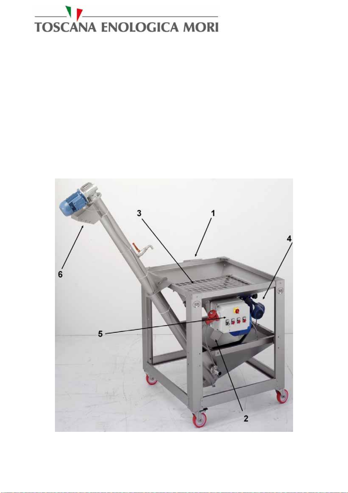
8.0 – Plant introduction and description
8.1 – Use and description
The machine has been designed and manufactured for a defined purpose (to prepare the crushing
stage of olives) and it may only be used for harvesting, cleaning and transport of olives.
Leaf remover is the first component of the olive oil extraction unit and it is used for harvesting,
separation and cleaning of olives from leaves, stones, branches and other foreign body and for
olives transport. Olives are poured into the receiving hopper (3), some water jets clean the olives
and all the heavy parts are conveyed on the bottom, while a fan removes the lights parts; than the
olives comes out of the machine by means of a screw elevator and go to the crusher. The plant is
basically comprised of the below listed modules:
1- Leaves outlet
2- Foreign bodies outlet
3- Olives loading hopper
4- Olives feed variator
5- Panel board
6- Clean olives outlet
Figure4 – Plant description

MINI DLE Instructions Handbook
12
8.2 – Illicit, improper or unauthorised use
The manufacturer declines any liability in the case of improper machine use, other than for the
purposes for which it has been designed and manufactured.
It is necessary to always carefully adhere to the rules of safety and to the instructions provided
herein. In particular, it is indispensable to comply with the operating limits stated in this handbook.
Unauthorised personnel must not be allowed near the equipment in use.
Use, maintenance and repairs are only allowed for suitably prepared and trained operators with their
own accident prevention equipment.
The manufacturer is also relieved of any liability in the case of:
•incorrect installation
•inadeguate maintainance
•tampering
•use of non genuine spare parts
•failure to adhere to the indications provided
•exceptional events.
Use of the machine is forbidden:
•in places of public access;
•in environments with the risk of explosion or fire;
•in environments containing contaminants such as powders, acids, corrosive gases, etc.;
•in environments where the possibility exists of exposing it to radiations;
8.3 – The User company’s responsibility
The User company is responsible for ensuring that the persons appointed to the various tasks:
•possess the requirements listed below;
•read and understand the instructions for use and maintenance;
•receive suitable training for the tasks entrusted to them and are capable of performing them
under safety conditions;
•receive specific training for correct use of the machine;
•have received appropriate individual protective devices.
•are in suitable physical and mental conditions (in any case not under the influence of
alcohol, medicines or drugs).
MINI DLE Instructions Handbook
13
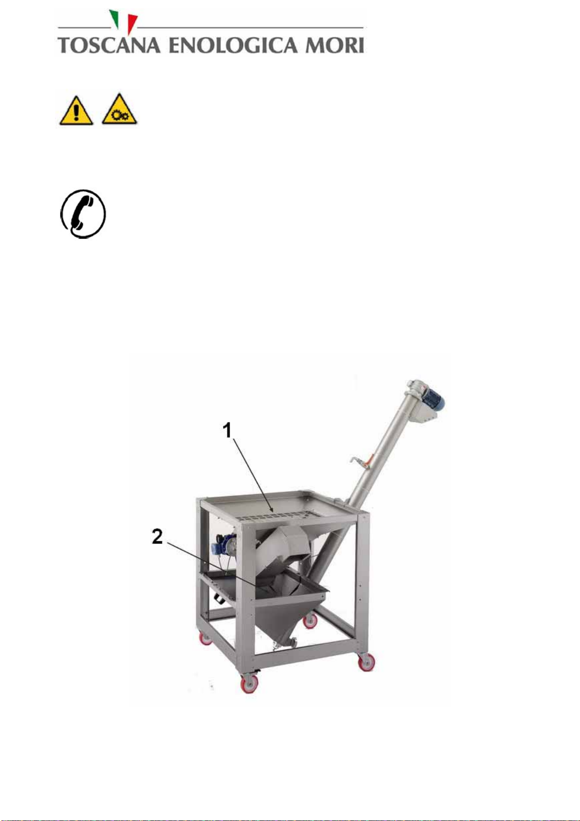
9.0 – Plant disassembly and assembly
WARNING:
Never start disassembly operations for any reason whatsoever before the machine has stopped
completely and the hot parts have cooled down. Make sure that the machine is not powered,
(remove the fuses or press the emergency button).
Place special notices to indicate that repair and/or maintenance work is in progress.
WARNING: For all other maintenance operations not mentioned in this handbook, it is
indispensable to contact an authorised TEM workshop.
9.1 – Equipment and safety systems used
1Safety grille on the hopper with openings having a maximum side of 60mm.
2 Safety grille on the hopper with openings having a maximum side of 60mm.
Figure 5 – Identification of safety systems used
MINI DLE Instructions Handbook
14
10.0 – Operation and use
WARNING Before starting up the plant for the first time, make sure that the
cleaning operation has been carried out. For subsequent start ups, check that there is no
foreign matter or residues from previous processes inside the plant, otherwise clean it before
using.
10.1 – Preparation for use
Before using the machine verify the followings:
-Verify that the electric connection is properly made refer to paragraph 13.5..
-Control the right hydraulic connections refer to paragraph 13.6.
-Control that the product receiving tanks are ready for use near the equipment.
-Verify that all the equipments to be used in a second step are efficient.
WARNING Pay attention to moving parts and augers. Do not insert foreign
matter, bulky, wooden or ferrous materials, or other.
WARNING During loading and unloading, it is absolutely forbidden to put the
hands and/or tools in the machine inlets and outlets.

MINI DLE Instructions Handbook
15
10.2 – Control and start up device
Figure 6 – Control board
The following table describes the controls shown in the previous figure.
MINI DLE Instructions Handbook
16
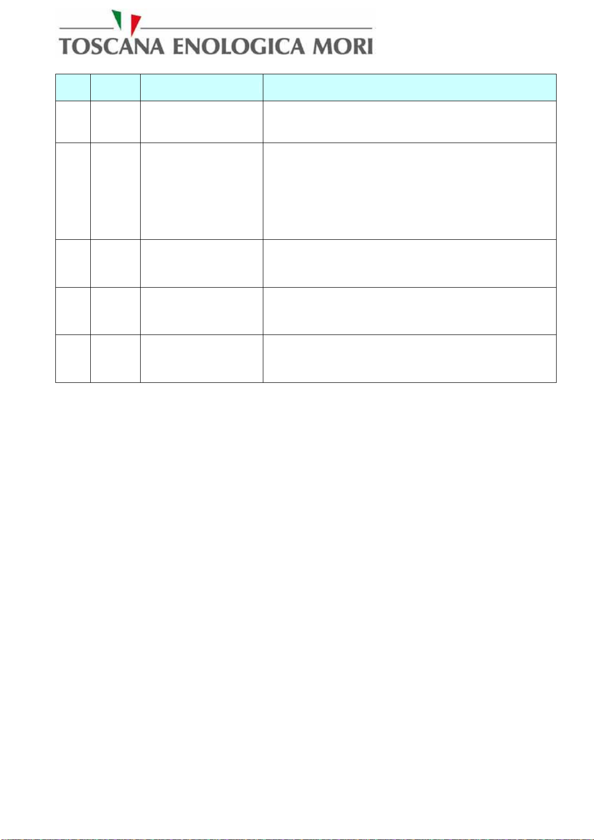
POS. Symbol DESCRIPTION PURPOSE
1 IG TWO POSITIONS
SWITCH ("ON” and
“OFF”) SET on “ON” THE MACHINE IS POWERED
2 AM TWO POSITIONS
KEY SELECTOR
(AUT-MAN)
SET on “AUT”- THE MINI DLE WORKS THROUGH
THE MACHINE ELECTRIC SYSTEM TO WHICH IT IS
CONNECTED (OLIOMIO50/100)
SET on “MAN” THE MINI DLE IS NOT POWERED BY
THE SYSTEM TO WHICH IT IS CONNECTED AND
IN CASE OF LACK OF POWER SUPPLY IT CANNOT
RE-START AUTOMATICALLY.
3 S1 TWO POSITIONS
SELECTOR (0-1) STARTS THE MOTOR OF THE VERTICAL SCREW OF
THE ELEVATOR
4 S2 TWO POSITIONS
SELECTOR (0-1) STARTS THE MOTOR OF THE OLIVES
HORIZONTAL SCREW
5 S3 TWO POSITIONS
SELECTOR (0-1) STARTS THEMOTOR OF THE DE-LEAFER
EXTRACTOR FAN
MINI DLE Instructions Handbook
17
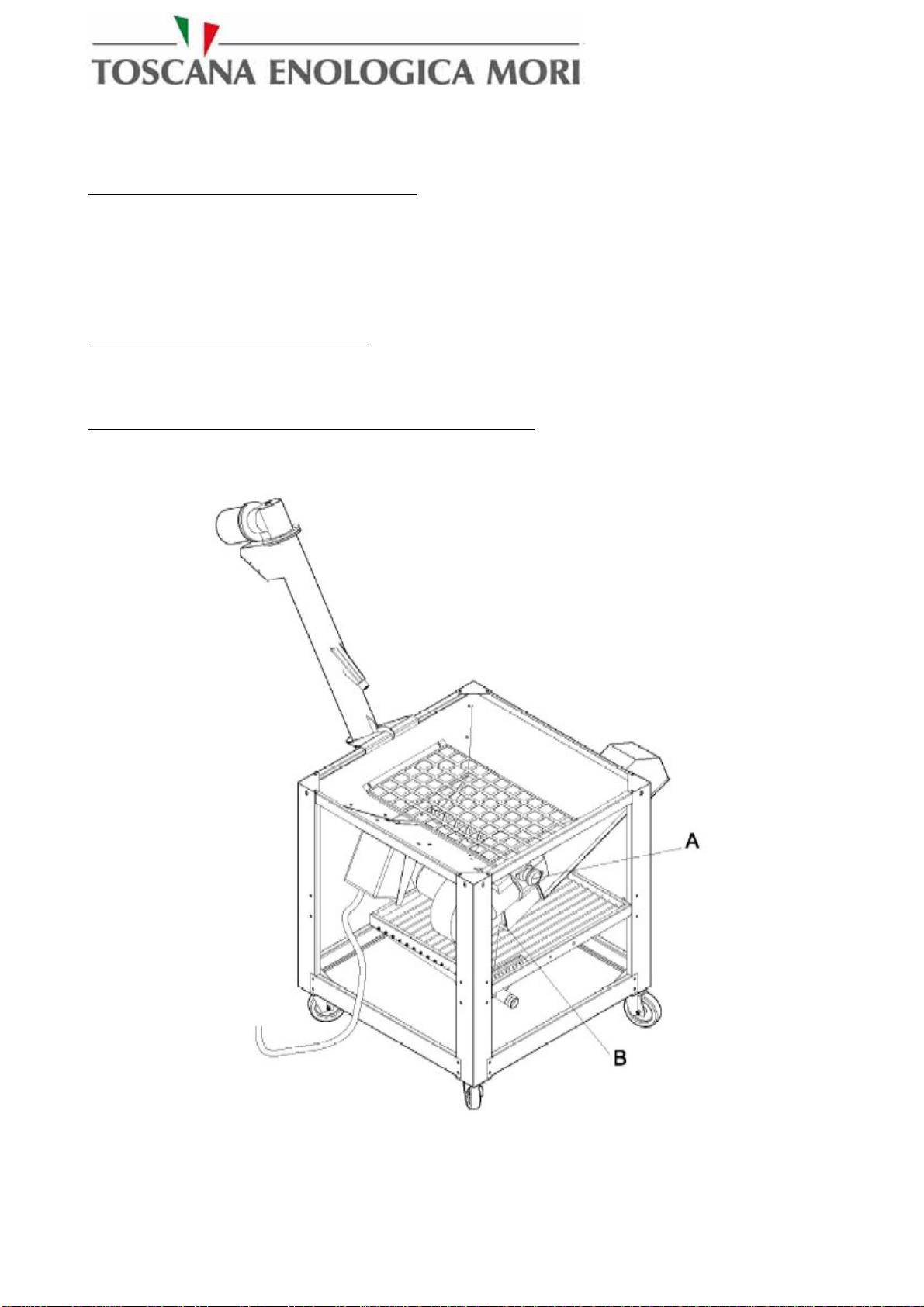
10.3 – Plant adjustments
ADJUSTMENT OF OLIVE FEED SPEED
The speed of the olive feed to the crusher can be adjusted using the Mini DLE-DLE-MAXIDLE
speed change drive unit adjustment flywheel (Increase – Decrease), when the crusher cannot drain
off the olives and the hopper is full; you have to decrease the speed. When the hopper is empty
increase the speed.
FAN ASPIRATION ADJUSTMENT
Leaves aspiration can be regulated through the opening of the air fan intake selvage (B). If there are
a lot of leaves in the olives that goes to the crusher you can open the air intake.
WATER REGULATION FOR CLEANING PROCEDURE
You have to regulate the water inlet flow to the DLE so that the tank overflow can maintain the
right level. Inlet of too much water let the water overflow to the floor.
Figure 1 – Adjustments

MINI DLE Instructions Handbook
18
10.4 – Machine starting and stopping
STARTING THE MACHINE
After the a.m. operation act as follows:
-Open water tap
-Move the general selector of the machine to CONNECTED.
-Move selector (S1) ELEVATOR to “1”.
-Move the selector (S2) horizontal OLIVE screw to “1”.
-Move the LEAF REMOVER selector (S3) to “1”.
-Now the machine is ready to work; adjust the speed of the olive feeding gear to set the right
quantity of olives to determinate the olive flow to the crusher.
-Load the DLE hopper with olives.
-
STOPPING THE MACHINE
Once the working cycle is to the end (stop to feed olives to the MINI DLE hopper!) proceed as
follows to stop the machine:
IMPORTANT:
Before stopping the machine verify that no more olives are going from the vertical hopper to the
crusher.
-Move the General switch to DISCONNECTED.
-Act on the MINI DLE board to disconnect all the commands.
10.5 – Operation control
Continuously feed the MINI DLE with olives, control the exit of leaves and dispose of them,
control the water flow for washing procedure.

MINI DLE Instructions Handbook
19
10.6 – Troubleshooting
WARNING:
Before doing any maintenance work, make sure that the electric plug is disconnected.
SYMPTOM CAUSE MEASURE
THE EMERGENCY IS
CONNECTED
Disconnect the mushroom button when
machine is connected.
MINI DLE UNIT IS
NOT STARTING POWER SUPPLY PLUG IS
NOT CONNECTED Properly connect the power supply plug.
MACHINE STOPS
AND THERMIC
SHUTDOWN LIGHT
IS ON
ONE OF THE MOTOR OF
THE LEAF REMOVER IS
IN THERMIC SHUTDOWN
Open the board and reput in service the
correspondent relay. IF the problem is not
solved contact after sale service.
MINI DLE Instructions Handbook
20
11.0 – Specifications
A table with technical specifications and a reference figure are included below for each unit
mentioned in paragraph 8.1.
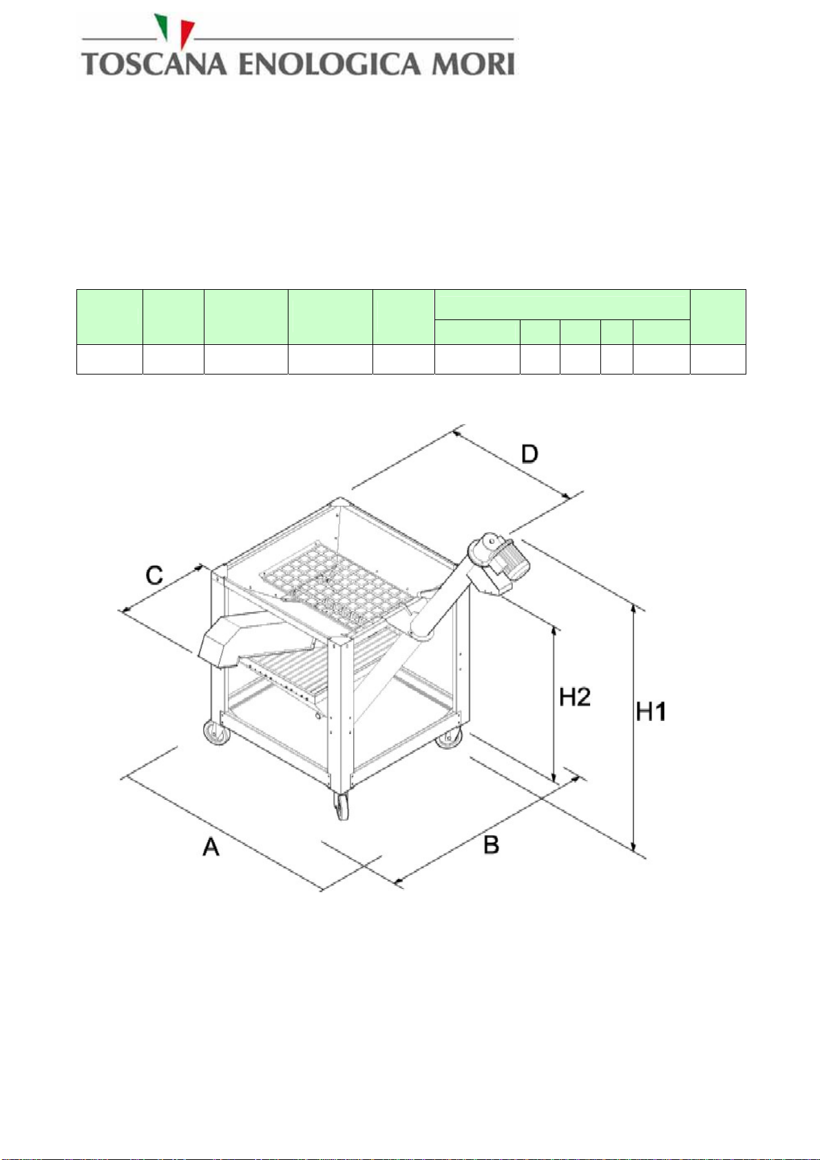
11.1 – MINI DLE
Figure 8 – MINI DLE dimensions
Dimensions in mm
Model Power Production
Kgs/hour Production
Kgs/8 hour Noise
Db AxB H1 H2 C D
Weight
in Kgs
Mini DLE 1 200 1600 75 1800x1000 1950 1570 350 1000 139
This manual suits for next models
2
Table of contents
Other Toscana Lawn And Garden Equipment manuals


