Toshiba LTA057A341F User manual

TO:Advantech Co.,Ltd.
CUSTOMER APPROVAL
Specification for:
LTA057A341F
Date of issue Nov 7,2008
Great Tech Corp.
6F., NO.309, Chuang-Ching Rd., Taipei, Taiwan
Tel:+886-2-27299268 Fax:+886-2-27298689
Customer Signature:

Specification No. TENTATIVE Sheet 1
Toshiba Matsushita Display Technology Co.,Ltd Date: 2008 – 11- 07
Date: - -
New No. LTA057A341F-14
Old No.
←# Special ←& Addition ←Change
Revision History
Date Rev.
Sheet
(New) Item Old New Reason

Specification No. TENTATIVE Sheet 2
Toshiba Matsushita Display Technology Co.,Ltd Date: 2008 – 11- 07
Date: - -
New No. LTA057A341F-14
Old No.
←# Special ←& Addition ←Change
Caution and Handling Precaution
For your end users' safety, it is strongly advised that the items with "∗" should be included in the instruction manual
of the system which may be issued by your organization.
Toshiba Matsushita Display Technology always endeavors to maintain sufficient quality in process of designing and
manufacturing. However, to avoid causing extended damages such as accidents resulting in injury or death, fire, or
social damages if the LCD module fails, take into consideration safe design such as redundant design, fire-spreading
prevention design, over-current prevention design, or malfunction prevention design etc. as a whole set.
For Safety
Warning
The following warning indicates a potentially hazardous situation which could result in death or serious injury if you do
not follow instructions.
1) SPECIAL PURPOSES
Toshiba Matsushita Display Technology’s Standard LCD modules described in this Specification are not customized
for applying to equipments (for example: nuclear control systems, airplanes and space vehicles, combustion control
systems, various safeguards, medical equipment etc.) of which failures or malfunctions may directly threaten a
human life or hurt a human body. When using them for the above equipments, consult with our company
beforehand.
Understand that our company cannot take responsibility for the damage etc. occurred by use without consultation.
2) ELECTRIC SHOCK
DISCONNECT POWER SUPPLY before handling LCD modules. In order to prevent electric shock, DO NOT TOUCH
the electrode part, cables, connectors, and the Light Emitting Diodes (hereinafter called “LED”) circuit part of a LCD
module in which LED are built in as a light source of a backlight or a front light.
Caution
The following caution indicates a potentially hazardous situation which may result in minor injury or moderate injury,
with incorrect usage.
∗1) DISASSEMBLING OR MODIFICATION
DO NOT DISASSEMBLE OR MODIFY the modules. Disassembling the module may result in an electric shock.
Sensitive parts inside LCD module may be damaged, and dusts or scratches may cause fire or breakage of circuits or
parts or surface damage of display. Toshiba Matsushita Display Technology does not warrant the modules, if
customer disassembled or modified them.

Specification No. TENTATIVE Sheet 3
Toshiba Matsushita Display Technology Co.,Ltd Date: 2008 – 11- 07
Date: - -
New No. LTA057A341F-14
Old No.
←# Special ←& Addition ←Change
∗2) BREAKAGE OF LCD PANEL
DO NOT INGEST liquid crystal material, DO NOT INHALE this material, and DO NOT PERMIT this material to
contact the skin, if glass of LCD panel is broken.
If liquid crystal material contacts the skin, mouth or clothing, take the following actions immediately.
In case contact to the eye or mouth, rinse with large amount of running water for more than 15 minutes. In case
contact to the skin or clothing, wipe it off immediately and wash with soap and large amount of running water for more
than 15 minutes. The skin or closing may be damaged if liquid crystal material is left adhered.
In case ingestion, rinse out the mouth well with water. After spewing up by drinking large amount of water, get medical
treatment.
∗3) GLASS OF LCD PANEL
BE CAREFUL WITH CHIPS OF GRASS that may cause injuring fingers or skin, when the glass is broken.
The LCD module has the structure where a plastic film is stuck on a glass surface and glass cannot disperse easily.
However, touching a cut surface may cause injuries.
4) ABSOLUTE MAXIMUM RATINGS
DO NOT EXCEED the absolute maximum ratings specified in this Specification. These are the rated values that
must not exceed for a LCD module by any means. Since the parts used as a circuit are damaged by fire or breakage
and the characteristic may not be recovered when exceeding this rating, take into consideration the variation in
ambient temperature, input signal change, and dispersed specification of electric parts etc., and design not to exceed
LCD module absolute maximum ratings.
5) POWER PROTECTION CIRCUIT
Employ protection circuit for power supply, for LCD module failures according to the operating condition of a set.
A suitable protection circuit should be applied, based on each system design.
DO NOT MODIFY the fuse used in the LCD module.
It may cause overheating and/or fire, if dust or metal particles touch the PCBs or failures of some circuits occur in the
LCD module.
6) DISPOSAL
Always comply with all applicable environmental regulations, when discarding the LCD module.
7) EDGES OF PARTS
Be careful with handling the metal flame (bezel) of a LCD module. Even though deburring treatment is performed, it
may cause injury. Be careful with edges of glass parts and touch panel identically. For designing the system, give
special consideration that the wiring and parts do not touch those edges.

Specification No. TENTATIVE Sheet 4
Toshiba Matsushita Display Technology Co.,Ltd Date: 2008 – 11- 07
Date: - -
New No. LTA057A341F-14
Old No.
←# Special ←& Addition ←Change
8) RECOMMENDED OPERATING CONDITIONS
Don't exceed “the recommended operation conditions” in this specification. (The LCD module should be used within
“the recommended operation conditions”.)
The performance and quality of the LCD module are warranted only when the LCD module is used within “the
recommended operation conditions”. Toshiba Matsushita Display Technology never warrants the performance and
quality of the LCD module when you use the LCD module over “the recommended operation conditions”, although
within “the absolute maximum rating”.
To use the LCD module over “the recommended operation conditions” may have bad influence on the characteristics
and reliability of the LCD module and may shorten the life of the LCD module.
Therefore, when designing the whole set, not to be over “the recommended operation conditions”, you should fully
take care of supply voltage change, characteristic of connection parts, serge of input-and-output line , and surrounding
temperature.
9) FEVER OF THE LED BACKLIGHT
LCD module’s upper and lower end portions (LED portions) get hot. The LEDs are built in the upper and lower end
portions of LCD module as backlight sources.
While LEDs are lit and immediately after turned off, the face of LCD module (display surface), top and bottom faces,
metal portions of right and left side faces, and metal portion of LED unit cover(s) on the back are hot and require
caution.
In case of touching (working on) such portion by necessity, surely disconnect the power to the LCD module
beforehand, protect hands (skin) with low thermal conductive gloves etc. or wait until the temperature of metal portion
gets as low as room temperature, and then touch (work on) the portion while being careful to prevent electrostatic
breakdown.
For Designing the System
2-1 DESIGNING ENCLOSURE
1) MOUNTING HOLES
Use all the mounting holes described in this Specification when assembling a LCD module in a set. Use screws
with a proper size described in this Specification.
∗2) TWIST/WARP
When assembling a LCD module in a set and using the set, be careful not to apply stress, such as twist or warp, on
the LCD module at designing an enclosure of the set. Twist or warp may cause LCD module failures.
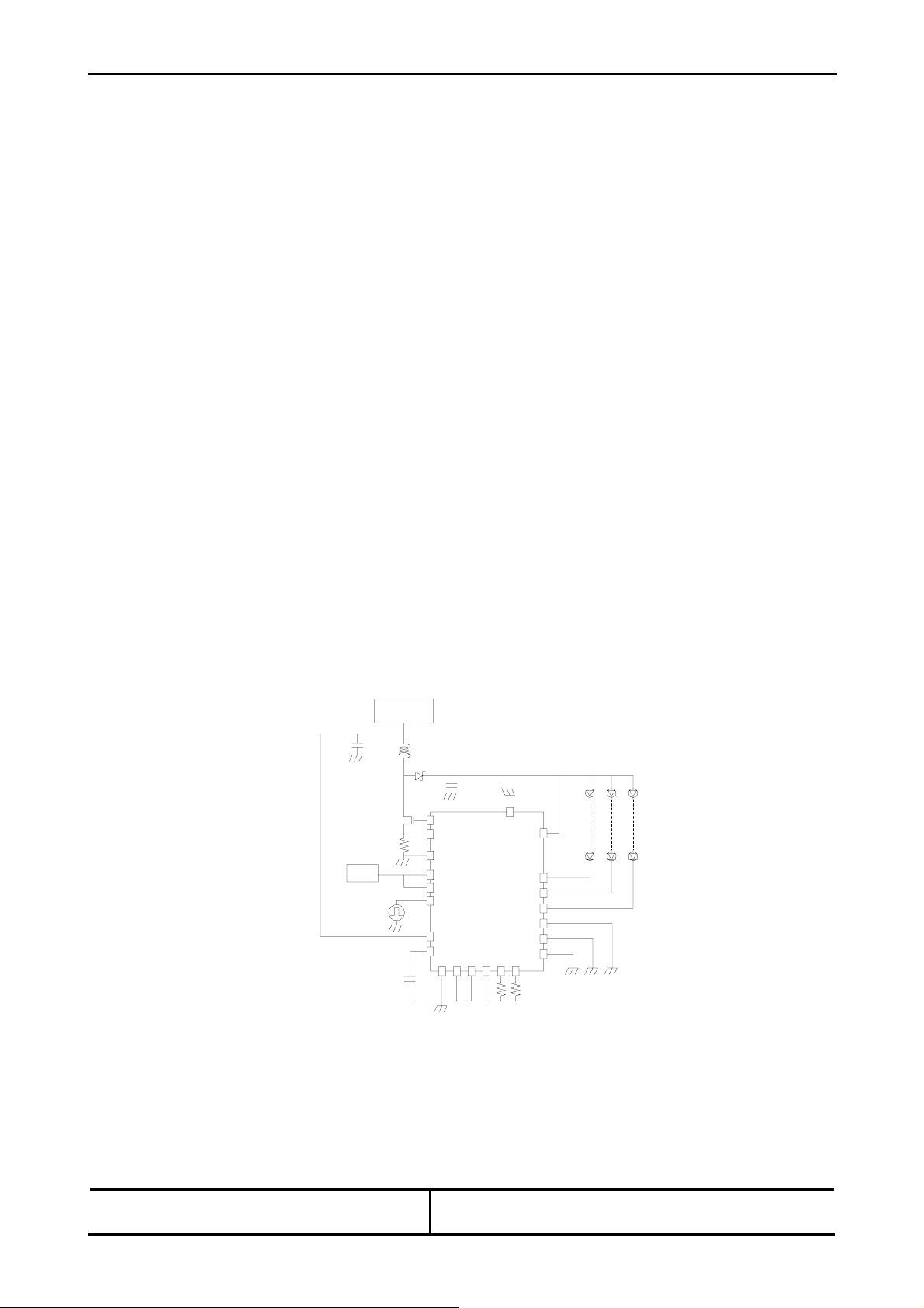
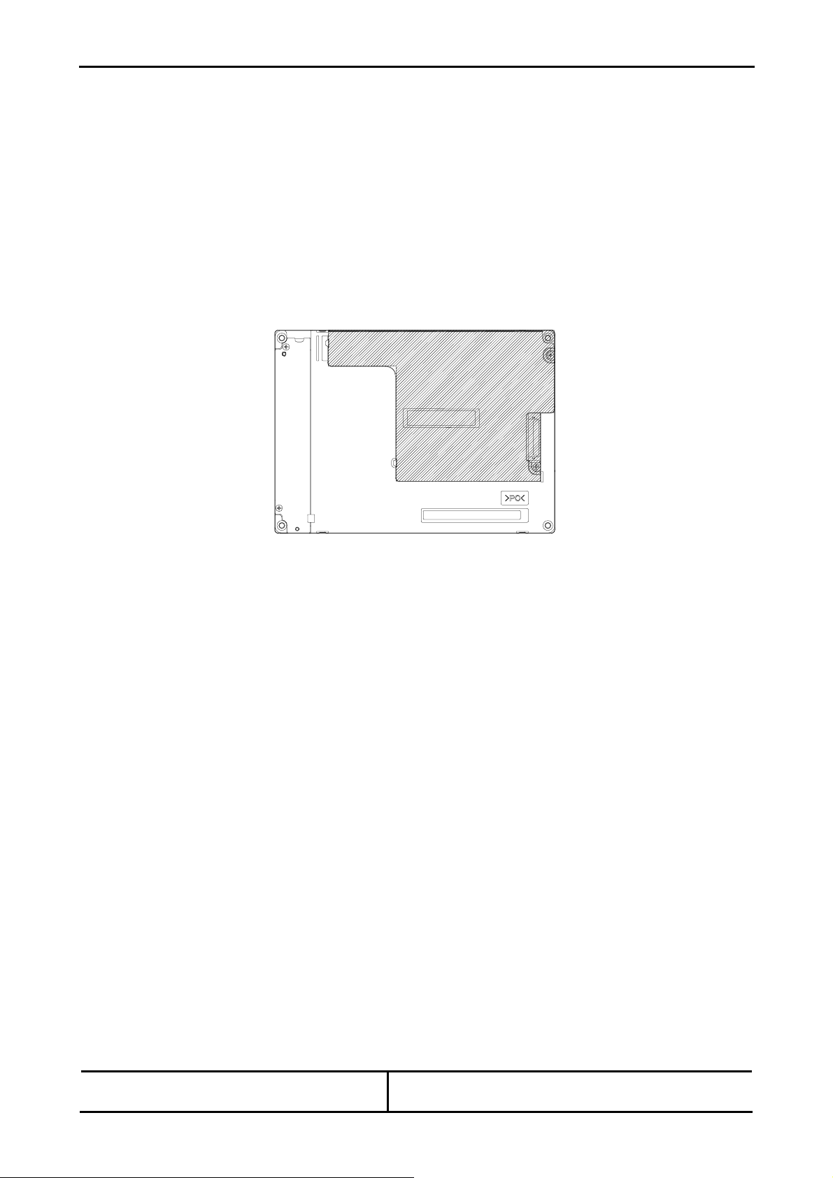
3) DESIGN ON THE REAR OF A LCD MODULE
Design a set so that the LCD module rear is not pressed by a set enclosure or a cable, etc.
Pressing the LCD module rear deforms a panel etc. and may cause ununiformity in a display. Design not to touch
the portion shown in oblique lines of the drawing below. This LCD module uses a light guide plate.
Applying stress on a light guide plate may causes white spots and black spots. Since applying stress on a circuit
board may cause damage, do not touch it.

Specification No. TENTATIVE Sheet 5
Toshiba Matsushita Display Technology Co.,Ltd Date: 2008 – 11- 07
Date: - -
New No. LTA057A341F-14
Old No.
←# Special ←& Addition ←Change
4) GAS GENERATED FROM THE PART MATERIAL FORASET
Some plastic materials and shock absorbing materials (rubber) used in the system may generate gases that may
cause the deterioration of the polarizer laminated on LCD’s panel or internal parts of the LCD module. Prior
confirmation is required.
5) GAS GENERATED FROM CASING /PACKAGING MATERIAL FOR A SET
Some materials used for packaging (for which sulfuric acid is used in the recycling process) generate gases that may
cause the deterioration of the polarizer laminated on LCD’s panel or internal parts of the LCD module. Prior
confirmation is required.
2-2. DESIGNING POWER SUPPLIES AND INPUT SIGNALS TO LCD MODULE
1) CAPACITY OF POWER SUPPLY
The fuse (KAMAYA /Type:FCC16152AB<TP>) is attached at the power supply line in the LCD module.
The sufficient electric capacity is needed for effective operation of this fuse. As for this fuse, there is no effect in the
former circuit. As an example, some parts such as I/F connector may be damaged with fire and/or smoke when the
power supply is shorted at I/F connector part. Have a suitable protection circuit also in the set side for accident
prevention. In equipping the set side with a fuse, please choose the fuse of suitable specification so that a fuse does
not blow by the rush current at operation start.
Power
Supply Recommended maximum
output current of
power supply
Recommended Fuse Rating
(in case of using fuse
forcurrentlimiter)
Built-in Fuse Rating
(for reference)
V
DD 4.0 A 1.5 A 1.5 A
2) SEQUENCE OF POWER SUPPLIES AND INPUT SIGNALS
Power-supply lines should be designed as follows.
Power supplies should always be turned on before the input signals are supplied to LCD module, and the input
signals should be disconnected before power supplies are turned off.
If this sequence is not followed, it may cause mis-operation of the panel.
Refer to "Sequence of Power Supplies and Signals" described in this Specification for details.
In addition, refer to individual specifications for unused terminals.
3) IMAGE STICKING IN A DISPLAY
Design the system not to display the same pattern for a long time.
Continuing the same pattern display for a long time or inputting the signals besides recommendation may cause the
phenomenon “image sticking” which remains vaguely after changing patterns.
4) GROUNDING FOR METAL FRAME(BEZEL)
Connecting metal frame (front bezel or/and rear case) of LCD module to ground is strongly recommended.
Generally grounding from metal frame of LCD module effects to improve endurance of ESD, various noise and
radiation interference from system design.
However, there are the above performance differences by system structure, so final conclusion for the grounding
should be decided after confirmation of matching with system side.

Specification No. TENTATIVE Sheet 6
Toshiba Matsushita Display Technology Co.,Ltd Date: 2008 – 11- 07
Date: - -
New No. LTA057A341F-14
Old No.
←# Special ←& Addition ←Change
2-3 DESIGNING FOR BETTER VISIBILITY
1) PANELANGLE
Visibility of LCD module deeply depends on the viewing directions. The position and the angle of LCD module in the
system should be designed so that the best visibility can be obtained at the actual usage.
2) WINDOW OPENING
Dimensions of window opening of the system's enclosure should be designed as smaller than "Viewing Area" and
larger than "Active Area" specified in individual specification in order to prevent that a part of screen is interrupted by
the enclosure and disappears.
3) PROTECTIVE COVER/ ULTRA-VIOLET CUT FILTER
In case of severe environmental condition like outdoor usage, a proper transparent protective cover (lens) over LCD
module is recommended, to prevent scratches, invasion of dust and water, etc, between the system housing and the
LCD module.
It is recommended to apply an ultra-violet filter (less than 390nm cut) onto the LCD module, for outdoor operation.
Strong ultra-violet radiation may damage the panel. However, in that case, transmittance-luminance will decrease.
Careful selection of material is required.
Don’t expose any parts, except the viewing area, into the direct sunlight, otherwise deterioration may occur.
2-4 DESIGNING LED POWER SUPPLY CIRCUIT
Make a design of stopping output, when an LED driving circuit becomes no-load (LED, FPC damage).
When the voltage input continuously with no-lighting LED, it may be smoke or fire.
For overcurrent protection, make a design of LED driving circuit with protective circuit (overcurrent
detector etc.).
To drive LED backlight, apply constant electric current by the following circuit diagram as reference. Please refer to
technical note of BD6583MUV (ROHM Co., Ltd.).
For Installation in Assembly
3-1 CARRYING
Hold a metal frame (bezel) part with both hands when carrying a LCD module with hand. Holding FPC may cause
failures, in the worst case, it may cause smoke and/or fire.
SENSN
SENSP
SW
RSTB
PWMPOW
PWMDRV
VBAT
VREG
GND GND GND GND
TEST
ISETL
VDET
LED1
LED2
LED3
LED4
LED5
LED6
FAILSEL
BATTERY
ON/OFF
← Each 15mA
200Hz
PWM
100mΩ
RTR020N05
4.7μH
10pF
2.2μF
1pF
POWER
3parallel
68kΩ
30kΩ
BD6583MUV
ROHM Co.,Ltd.

Specification No. TENTATIVE Sheet 7
Toshiba Matsushita Display Technology Co.,Ltd Date: 2008 – 11- 07
Date: - -
New No. LTA057A341F-14
Old No.
←# Special ←& Addition ←Change
3-2 CAUTIONS TO PREVENT FROM ELECTROSTATIC DESTRUCTION UNDER ASSEMBLY WORK
Consider the following to prevent the static electricity from generating under assembly work. High-voltage static
electricity discharge destroys the circuit inside the module and it may cause failures
1) HUMIDITY
Maintain a work place in the range of 50 to 70% of relative humidity, to prevent generation and discharge of static
electricity.
2) GROUNDING
2-1) Cover the floor of a work area and a work desk with a conductive mat, and ground them, through resistance with
range of 0.5 MΩto 1MΩ, to prevent discharge all at once.
2-2) Workers must wear a grounded wrist band.
2-3) Ground all metallic tools, jigs and equipment, such as a soldering iron and a screw driver, jigs, conveyors, or
metallic work benches, which are to be used for assembly work.
3) IONIZER
Using ionizer (an antistatic blower) is recommended at working area in order to reduce electro-static voltage.
4) REMOVING PROTECTION FILM
The protection film is stuck on an LCD panel before its shipment to prevent dust or scratch on the panel during
transportation, assembly work and otherwise. Remove a protection film on an LCD panel near the last process of
an assembly to prevent dust and scratch on the panel.
However, remove the film in advance in case of a set attached a module is inserted into high temperature chamber
for aging etc. If it is left without removing the film, it may cause irregular polarizer surface.
When removing the protection film, peel off the film from its edge, using round-ended tweezers with Teflon coating or
a cellophane tape attached on the edge of the protection film, carefully and slowly, spending more than 3 seconds.
In peeling off the protection film, blow the film using ionizer to eliminate ESD from the film.
Removal which does not comply with the above procedure may generate ESD and damage electric circuit of a LCD
module.
5) Do not touch bare metal portions of examination /inspection equipment. It causes to discharge electric charge of an
object or a human body.
6) Do not touch the mounting parts of PCB LCD module, circuit patterns or connector terminals with worker’s hand or
conductive tools.
3-3 DUST AND STAIN PREVENTION
1) WORKING AREA
Handle the LCD module in the room without metallic dust. Especially when metallic dust adheres to the LCD module,
an internal electric circuit makes short-circuited and it may cause failures.
2) FINGER PRINT
Handle the LCD module fingerstalls or soft and dust-free gloves that do not produce dust when performing incoming
inspection of modules or assembling sets. Handling them with bare hand may damage module display quality.

Specification No. TENTATIVE Sheet 8
Toshiba Matsushita Display Technology Co.,Ltd Date: 2008 – 11- 07
Date: - -
New No. LTA057A341F-14
Old No.
←# Special ←& Addition ←Change
∗3) WIPING OFF DUST ON THE PANEL
When LCD panel becomes dirty, wipe the panel surface off softly with absorbent cotton or another soft cloth.
If necessary, breathe upon the panel surface and then wipe off immediately and softly again.
Be careful not to spill organic solvents into the inside of LCD module. The organic solvents may damage driver IC
and PCB area used inside module.
The polarizer laminated to LCD panel and adhesives may be damaged by organic the solvents, so do not use any
organic solvents for wiping off LCD panel.
4) PROTECTION AGAINST ADHESION OF ADHESIVE OR GREASE ONA DISPLAY
Be careful not to attach adhesive or grease etc. used for the assembly of a set on a LCD module display.
It is difficult to remove them without damaging display quality.
∗5) WATER DROP ON A DISPLAY
Do not leave water drop attached on a display. When water drop etc. is attached, wipe it off with absorbent cotton or
soft cloth etc. immediately. If it is left without wiped off, a display discolors, or it causes spots. Moreover, moisture’s
infiltration into the inside causes failures.
6) HANDLING IN THE CORROSIVE ATMOSPHERE
Do not blow gas or do not use a LCD module beside the normal atmosphere. It may cause failures.
3-4 BENDING / TWISTING OF LCD MODULE UNDER ASSEMBLY
1) INSTALLING LCD MODULE TO THE ENCLOSURE
Do not bend or twist LCD module even momentary when LCD module is installed into an enclosure of the system.
Bending or twisting LCD module may cause its damages.
2) FASTENING SCREWS
Fasten equally screws, which attach a module in a set,. If not fastened equally, temporarily warping or twisting of the
LCD module may cause failures.
3) FOR PREVENTION OF CATCHING CABLES
Be careful not to let cables etc. for interface caught between a set enclosure and a LCD module while assembling a
LCD module in a set.
Assembling with cables caught in may cause bending, twist of a LCD module, or damage and failure of cables.
3-5 MECHANICAL FORCES
∗1) STRONG MECHANICAL SHOCK
Avoid strong mechanical shock, such as dropping the LCD from the work bench, or knocking it against a hard object.
These may cause the glass panel to crack, or cause other mis-operation.
∗2) EXCESSIVE FORCE
Avoid applying excessive force, like pushing the surface of LCD panel. This may cause scratches or breakage of
the panel, or a failure of the module.

Specification No. TENTATIVE Sheet 9
Toshiba Matsushita Display Technology Co.,Ltd Date: 2008 – 11- 07
Date: - -
New No. LTA057A341F-14
Old No.
←# Special ←& Addition ←Change
∗3) PREVENTION FOR SCRATCHES ON A DISPLAY
Be careful not to touch a module display with hard things, such as a tool etc., press a module display with them or
rub a module display with them.
Moreover, be careful not to put heavy things, such as a tool etc., or pile up LCD module displays.
As polarizing plates used for a display is easy to be damaged, it may cause scratches, trace, or breakage of the plate.
∗4) HANDLING THE REAR OFA LCD MODULE
There are mechanically weak parts, such as a circuit board etc. in the LCD module rear shown in oblique lines
portion of the drawing below.
Be careful that circuit and parts may be damaged and a LCD module may fail if applying stress when assembling a
LCD module in a set or handling it.
5) HOW TO INSERT CONNECTOR
Be careful not to apply a strong external force on the connector of a LCD module when inserting or removing cables
to connectors of a module. A strong external force may damage internal connections of PCB or TAB driver.
Insert them correctly so that connectors for LCD module input signals and connection connectors of a set are not
inserted oblique or half, and be sure to check them.
When inputting signals etc. without inserting them correctly, it may cause failures of circuit parts.
6) HANDLING FPC
Be careful not to pull FPC or damage FPC. It causes failures.
3-6 OPERATION
Be sure that the following caution should be taken under assembly and inspection of the system.
1) POWER SUPPLY WHILE WORKING/ASSEMBLING
Be sure to turn off the power of a set while working. Pulling out and inserting a LCD module connector with the
power of a set turned on may damage a LCD module electric circuit. When turning on the power in a testing
process, an inspection process etc., use the power supply and input signals for a drive unit which satisfy the power
supply sequence described in this Specification.
2) INPUT SIGNAL
The signal should be applied after power supplies are turned on.
The signal should be removed before power supplies are turned off.
The detailed sequence of power supplies and signals are described in this specifications.

Specification No. TENTATIVE Sheet 10
Toshiba Matsushita Display Technology Co.,Ltd Date: 2008 – 11- 07
Date: - -
New No. LTA057A341F-14
Old No.
←# Special ←& Addition ←Change
∗3) LCD LONG PERIOD OPERATION
In case of LCD module long period operation, discoloration of light guide or optical sheet will be happened (due to
ultra violet and heat from FL tube). As the result, there is a possibility to have out of specification for the optical
characteristic as “5.2”. But this is not irregular phenomena.
4) LED LIFE
Please note that LED life will be shorter than the average life described in the Specification if the ambient
temperature is higher than 25°C.
Moreover, when LED current exceeded a recommended electric current, LED life will be shorter than the average life.
5) LCD MODULE REPLACEMENT FROM SYSTEM
When replacing LCD module, turn off supply voltage and input signal to the LCD module, surely disconnect the
power supply to the circuit for lighting the backlight (not only by turning off the control signal to ON/OFF terminal etc.),
and then replace the LCD module.
For Transportation and Storage
1) STORAGE UNDER HIGH TEMPERATURE AND HIGH HUMIDITY
Be careful not to store a LCD module for a long time (about one month or more) under the condition of high
temperature and high humidity (35 ºC or more, 70% or more of relative humidity). This may deteriorate display
quality.
When it is necessary to store unavoidably for a long term, in the state of packing by our company (before opening),
store it within the range of 0 ºC to 35 ºC and in the dry place of 70% or less of relative humidity.
2) SOLIDIFICATION ON THE LIQUID CRYSTAL IN CRYOGENIC CONDITION
Since a temperature lower than a rated storage temperature described in this Specification may damage a LCD
module liquid-crystal-display panel due to the solidification or contraction etc. on liquid crystal, be careful not to
leave it in such a place.
3) BE CAUTIOUS OF STRONG ULTRAVIOLET
Be careful not to expose a LCD module to the sunlight or a fluorescent light directly to protect a LCD module from
strong ultraviolet, when storing modules for a long term.
4) CLEANLINESS
Keep the LCD module in clean place, because any dust, hard particle may damage the polarizer, or dust invades the
inside of the LCD module.
∗5) CONDENSATION OF WATER
The modules should be stored under a condition which no condensation of water is allowed. It may cause
mis-operation or defects. Be especially careful not to make a module work under the condition that condensation of
water appears.
6) REPACKAGING
Use the original packing box, material, and method when repacking for transporting and storing it again.
7) NOTES FOR THE ADOPTION OF NEW PACKING MATERIAL
Since some of the cartons for packing or the rubber parts etc. generate corrosive gas, confirm a reliability check in the
set assembling state or the packing state before the adoption.

Specification No. TENTATIVE Sheet 11
Toshiba Matsushita Display Technology Co.,Ltd Date: 2008 – 11- 07
Date: - -
New No. LTA057A341F-14
Old No.
←# Special ←& Addition ←Change
- CONTENTS -
Revision History Sheet 1
Caution and Handling Precaution 2
1. Scope 12
2. Product Specifications 12
2.1 General Specifications
2.2AbsoluteMaximumRatings 13
2.3MechanicalSpecifications 14
2.3.1 Weight
2.3.2DimensionalOutline 15
2.4ElectricalSpecifications 17
2.4.1 Circuit Diagram
2.4.2 Sequence of Power Supplies and Signals
2.4.3TimingChart 18
2.4.4TimingSpecifications 19
2.4.5ReverseFunctionSetting 20
2.4.6InterfaceConnector 21
2.4.7ColorsCombinationTable 22
3. Recommended Operating Conditions 23
4. Electrical Characteristics 24
4.1 Test Conditions
4.2 Specifications
5. Optical Characteristics 25
5.1 Test Conditions
5.2 Optical Specifications
6. Quality 26
6.1 Inspection AQL
6.2 Test Conditions
6.3 Dimensional Outline
6.4AppearanceTest 27
6.4.1 Test Conditions
6.4.2 Specifications
6.5DisplayQuality 28
6.5.1 Test Conditions
6.5.2 Specifications
6.6ReliabilityTest 29
6.6.1 Test Conditions
6.6.2 Specifications
6.7Labels 30
7. Lifetime 31
7.1 Module
7.2 LED
7.2.1 Test Conditions
7.2.2 Specifications
8. Packaging 32
8.1 Carton
9.Warranty 33
10. Regulation 33
10.1 Regulation
10.2 Environment
11. Measuring Method 33
11.1 Measuring Systems
11.2 Measuring Methods

Specification No. TENTATIVE Sheet 12
Toshiba Matsushita Display Technology Co.,Ltd Date: 2008 – 11- 07
Date: - -
New No. LTA057A341F-14
Old No.
←# Special ←& Addition ←Change
1. Scope
This specification is applicable to Toshiba Matsushita Display Technology's 14cm diagonal size TFT-LCD module
"LTA057A341F" designed for Industrial.
2. Product Specifications
2.1 General Specifications
Item Specifications
Display Mode1) TN color(64 gray scales, 256k colors)
Transmissive type, Normally white
Viewing Direction 6 o'clock (in direction of maximum contrast)
Driving Method TFT active matrix
Input Signals CLK (clock), DE (Data Enable signal)
H-sync, V-sync (Synchronization signal)
R5, R4, R3, R2, R1, R0 (Red display data)
G5, G4, G3, G2, G1, G0 (Green display data)
B5, B4, B3, B2, B1, B0 (Blue display data)
R/L, U/D (Reverse Scan Control)
Dimensional Outline2) 144.0 (W) ×104.6 (H) ×8.3 Max. (D) (mm)
Active Area 115.2 (W) ×86.4 (H) (mm)
Viewing Area 115.4 (W) ×86.6 (H) (mm)
Number of Pixels3) 320 (W) ×240 (H) (mm)
Pixel Pitch3) 0.36 (W) ×0.36 (H) (mm)
Pixel Arrangement3) RGB vertical stripes
Surface Treatment Anti-glare and hard coat 3H on LCD surface
Backlight 18 LEDs (3 rows ) for sidelighting
Note 1) k=1024
Note 2) Excluding backlight cables.
Note 3) Display area address is as follows.
1 2 319 320
1 R G B R G B RGBRGB
2 R G B R G B RGBRGB
RGB :pixel
RGB :Sub-pixel
(Dots)
239 R G B R G B RGBRGB
240 R G B R G B RGBRGB 0.36mm
0.36mm

Specification No. TENTATIVE Sheet 13
Toshiba Matsushita Display Technology Co.,Ltd Date: 2008 – 11- 07
Date: - -
New No. LTA057A341F-14
Old No.
←# Special ←& Addition ←Change
2.2 Absolute Maximum Ratings 1)
Item Symbol Min. Max. Unit Checked Terminal
4)
Supply Voltage VDD -0.3 +4.0 V VDD to GND
Input Voltage of Signals VIN -0.3 VDD+0.3 V
R5 to R0, G5 to G0, B5 to B0
CLK, DE, H-sync, V-sync,
R/L, U/D
above each terminal to GND
LED Supply Voltage VLED - +30.0 V
VLED1- to VLED1+,
VLED2- to VLED2+,
VLED3- to VLED3+
LED Input Current 5) ILED - 30 mA
Operating Ambient Temperature2) 3) TOP -20 +70 °C
Operating Ambient Humidity2) HOP 10 90 %(RH)
Storage Temperature2) TSTG -30 +80 °C
Storage Humidity2) HSTG 10 90 %(RH)
Note 1) Do not exceed the maximum rating values under the worst probable conditions taking into account the supply
voltage variation, input voltage variation, variation in part constants, and ambient temperature and so on.
Otherwise the module may be damaged.
Note 2) Wet bulb temperature should be 39°C Max, and no condensation of water. See figure below.
Note 3) Only operation is guarantied at Operating Temperature. Display quality is evaluated at +25 °C.
Note 4) Refer to 2.4.6
Notes 5) Do not exceed the maximum current value for environmental temperature as the below LED characteristic’s
chart.
Dry Bulb Temperature [ C]
Operation
Storage
Humidity[%(RH)]
Wet Bulb
Temperature [ C]
40%
60%
80%90%
20%
10%
50
40
30
20
10
0
010 20 30 40 50 60 70 80
-10
-20
-30

Specification No. TENTATIVE Sheet 14
Toshiba Matsushita Display Technology Co.,Ltd Date: 2008 – 11- 07
Date: - -
New No. LTA057A341F-14
Old No.
←# Special ←& Addition ←Change
2.3 Mechanical Specifications
2.3.1 Weight
125 ±30g
ILED (mA)

Specification No. TENTATIVE Sheet 15
Toshiba Matsushita Display Technology Co.,Ltd Date: 2008 – 11- 07
Date: - -
New No. LTA057A341F-14
Old No.
←# Special ←& Addition ←Change
2.3.2 Dimensional Outline Unit:mm
(front figure) StandardTolerance: ±0.5
Main viewing
angle direction
12.5
8
144
104.6
1.5
6.2
1.2
1.2 1.5
2.5
4 4
60.6 22
89.4 7.6
4.5
7
8.3 MAX.
4-diameter 5
90.2(Bezel Opening)
86.4(Active Area)
4
5.9+/-0.8
115.2(Active Area)
119(Bezel Opening)
14.4+/-0.8 (14.4)
(12.5)
4-R0.3 4-R0.3
depth max 3.1
4-diameter 1.6
2
8.3 MAX.
8.3 MAX.
(10.4)
(12.3)
4-hole depth max 3.1

Specification No. TENTATIVE Sheet 16
Toshiba Matsushita Display Technology Co.,Ltd Date: 2008 – 11- 07
Date: - -
New No. LTA057A341F-14
Old No.
←# Special ←& Addition ←Change
(back figure) Unit:mm
StandardTolerance:±0.5
16
CN1
CN2
1
136.6 3.7
8.3
96.4 4.1
12.7+/-1
4.5+/-1
49.1+/-1
33
depth max. 4.2
4-diameter 2.6

Specification No. TENTATIVE Sheet 17
Toshiba Matsushita Display Technology Co.,Ltd Date: 2008 – 11- 07
Date: - -
New No. LTA057A341F-14
Old No.
←# Special ←& Addition ←Change
0.2V 0.2V 0.2V
500ms(min.)
0ms(min.)
0.2V
3.0V 3.0V
DD DD
40ms(max.)
0.5ms(min.)
10ms(max.)
0.2V
0.1ms(min.)
100ms(max.)
0ms(min.)
40ms(max.)
DATA
DE
H,V-sync
CLK
U/D,L/R
V
DD
0ms(min.)
250ms(min.)
LED B/L
OFF
ON
2.4 Electrical Specifications
2.4.1 Circuit Diagram
2.4.2 Sequence of Power Supplies and Signals
Notes 1) When turn VDD on and turn it off, the form of voltage should be input with no ripple signal.
I/F Connector
CN1
DC/DC
Manipulation
Gray Scale
Voltage
Generation
Circuit
Converter
Panel
Controller
LCD Panel
CN2
LED LED LED
Connector
Y-Driver IC
X-Driver IC
320 x 240 pixels

Specification No. TENTATIVE Sheet 18
Toshiba Matsushita Display Technology Co.,Ltd Date: 2008 – 11- 07
Date: - -
New No. LTA057A341F-14
Old No.
←# Special ←& Addition ←Change
2.4.3 Timing Chart
tv
tvw
Vsync
tvfp
th
tvd
tvds
tvblnk
Hsync
DE
12239 240
th
thw
thde
thds
thfp
320
1234
Hsync
DE
RGB Data
NCLK
tvd

Specification No. TENTATIVE Sheet 19
Toshiba Matsushita Display Technology Co.,Ltd Date: 2008 – 11- 07
Date: - -
New No. LTA057A341F-14
Old No.
←# Special ←& Addition ←Change
2.4.4 Timing Specifications 1) 2) 3) 4) 5) 6)
Item Symbol min. typ. Max. unit
260 262 340
th
Frame Period tv 15.9 16.66 17.81 ms
Vertical Display Term tvd 240 240 240
clk
Vertical Blanking Term tvblnk 20 22 100
th
V-sync Pulse Width tvw 1.0 2.0 3.0
th
Vertical Data Sync Period tvds 10 18 20
th
410 424 436
tc
Horizontal Period th 49.5 63.6 64.1 us
Horizontal Display Term thde 320 320 320
tc
H-sync Pulse Width thw 3 51 80
tc
Horizontal Front Porch thfp 16 18 40
tc
Horizontal Data Sync Period thds 50 86 100
tc
Clock Period tc 120 150 156 ns
Clock "H" Time tch 7.0 --- --- ns
Clock "L" Time tcl 7.0 --- --- ns
Data Setup Time tds 5.0 --- --- ns
Data Hold Time tdh 2.0 --- --- ns
Note 1) If DE is fixed to “H” or “L” level for certain period while CLK is supplied, the panel displays black with some flicker.
Note 2) Don’t fix CLK to “H” or “L” level while the VDD(+3.3V) is supplied.
If CLK is fixed to "H" or "L" level for certain period while DE is supplied, the panel may be damaged.
When It holds on, DC voltage supplies to liquid crystal materials and It may cause damage to liqud crystal
materials.
Note 3) Display area address is as follows.
Note 4) Do not make tv, th and tvds fluctuate.
Iftv, th and tvds are fluctuate, the panel displays black.
Note 5) In case of using the long frame period, the deterioration of display quality, noise etc. may be occurred.
Note 6) CLK count of each Horizontal Period (th) should be always the same.
Vertical blanking term should be “n” X “Horizontal Period” (th). (n: integer)
Frameperiod(tv) should be always the same.
X,Y
X,2
X,1
1,Y
1,2
1,1
320 pixels
240 pixels
320,1
320,2
320,Y
320,240X,2401,240
Table of contents
Popular Industrial Monitor manuals by other brands

Nexcom
Nexcom APPD 1205T user manual

Omron
Omron NB3Q-TW00B Startup guide manual

Contemporary Research
Contemporary Research FT1-3 product manual

ADLINK Technology
ADLINK Technology SP-15W03 Series user manual

GPO Display
GPO Display NSV series manual

Rockwell Automation
Rockwell Automation 6186-M12AL user manual