Chipsee PPC-A72-215-C User manual


19
Horizontal Resolution
80 Means 800 Pixel
10 Means 1024 Pixel
12 Means 1280 Pixel
14 Means 1440 Pixel
19 Means 1920 Pixel
108
Vertical Resolution
480 Means 480 Pixel
600 Means 600 Pixel
768 Means 768 Pixel
800 Means 800 Pixel
900 Means 900 Pixel
102 Means 1024 Pixel
108 Means 1080 Pixel
R(T/F) Product based on Rockchip (TI/Freescale) CPU
215
LCD Dimension
050 Means 5.0 Inch
070 Means 7.0 Inch
080 Means 8.0 Inch
097 Means 9.7 Inch
101 Means 10.1 Inch
104 Means 10.4 Inch
120 Means 12.0 Inch
125 Means 12.5 Inch
150 Means 15.0 Inch
156 Means 15.6 Inch
170 Means 17.0 Inch
190 Means 19.0 Inch
215 Means 21.5 Inch
P
Means Embedded PC or Panel PC
E Means Embedded PC without Case
P Means Panel PC with Case
C
Means Touch Type
R Means Resistive Touch
C Means Capacitive Touch

1
Means LCD Brightness
• Means Common Brightness
• Means High Brightness
1PCB Version
Baseboard PCB Version Number
1PCB Version
SOM Module PCB Version Number
Hardware Features
Key Features:
CPU Rokchip RK3399, Dual-core Cortex-A72
(1.8GHz), Quad-core Cortex-A53 (1.4GHz)
RAM 4GB DDR3
eMMC 16GB
Storage TF card supports up to 32GB SDHC
Display 21.5 Inch LCD, 1920*1080 Pixel Resolution
Touch Ten-Point Capacitive Touch
USB 4 x USB 2.0 Host, 1x USB 3.0 Host, 1x
Type-C
LAN 1 Channel 1000M LAN
Audio 3.5mm Audio In/Out Connector, 2W Speaker
Internal
Buzzer 1
RTC Yes
RS232+RS485 7 Channels (4 x RS485 at most, 1 debug
port)
GPIO Optional
WiFi/BT On-Board WIFI/BT

HDMI 1 Channel
4G/LTE Optional
Power Input 15~36V DC
Current @ 15V 1A max
Power Consumption 15W Typical
Working Temperature 0°C to +70°C
OS Android 7.1, Android 9.0
Dimension 530*322*45mm
Weight 6000g
CS19108R215P-
C111
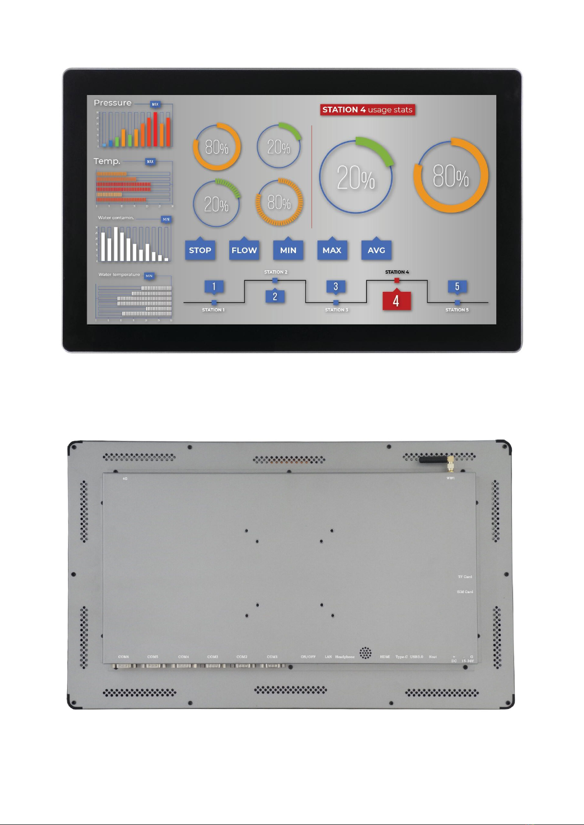
Figure 1: Front View
Figure 2: Back View
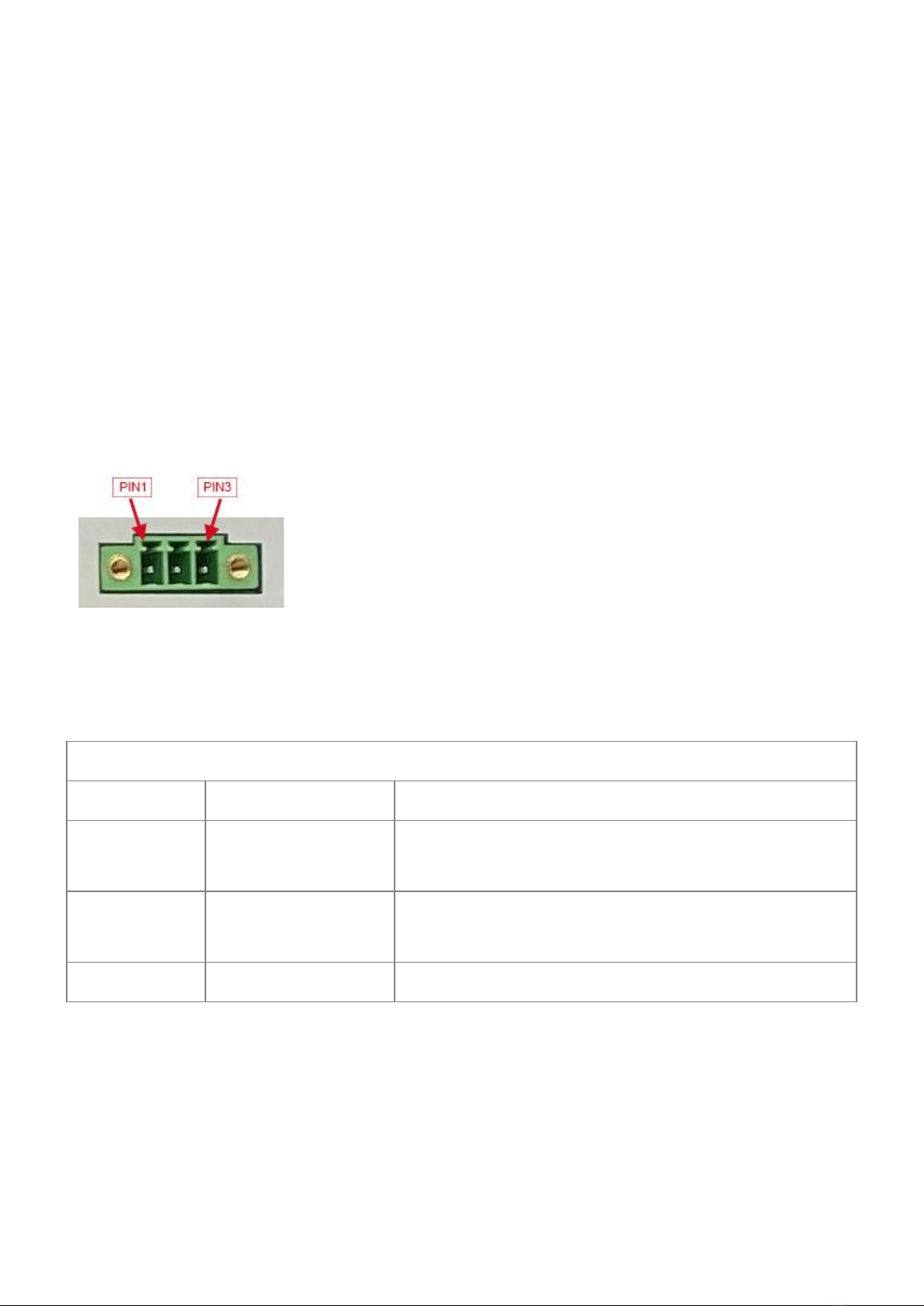
Power Input Connector
The product CS19108R215P uses a wide-range power input DC
15~36V. The total power consumption is normally about 15W. The
power input connector is a 3 pin 3.81mm screw terminal
connector, as shown in Figure 3.
A detailed description of the power input connector pins is
provided in Table 1.
Figure 3: Power Input Connector
Table 1
Power Input Pin Definition:
Pin Number Definition Description
Pin 1 Positive Input Connect to DC Power Positive
Terminal
Pin 2 Negative Input Connect to DC Power Negative
Terminal
Pin 3 Ground Connect to Power System Ground
ATTENTION:
The system ground “G” has been connected to power negative “-
” on board.

Capacitive Touch
The product uses a ten-point capacitive touch screen.
ATTENTION:
Capacitive touch screens are very sensitive to power noise.
Ripple voltage/current from the power adapter can cause the
LCD ripples, as well as the capacitive touch malfunction. If
you use the APK Multi-Touch under Android to test it, you can
find the touchpoint float. There are several ways to solve
this problem:
1) Use a high-quality power adapter. Or a battery to provide
power like a cell phone or tablet PC.
2) If the power adapter isn’t good enough, make sure the
power input connector Pin 3 is connected to the Ground. This
method can eliminate the problem totally. You can test it by
touching the GND with one hand, while the other hand operates
on the capacitive touch screen. In this case, the user’s body
acts as the Power System Ground.
DB9 Connector
There are six serial ports available with DB9 connector, all
configured in RS232 mode by default (COM1 to COM6). You can
set COM3 to COM6 in RS485 mode. If you need a different
configuration, please contact us.

Figure 4: DB9 Connector
USB 2.0 Connector
There are four USB 2.0 connectors, as Figure 5 shows. Each can
provide 500mA of current.
Figure 5: USB 2.0 Connector
USB 3.0 Connector
And one USB 3.0 connector, as shown in Figure.
Figure 6: USB 3.0 Connector
USB Type-C
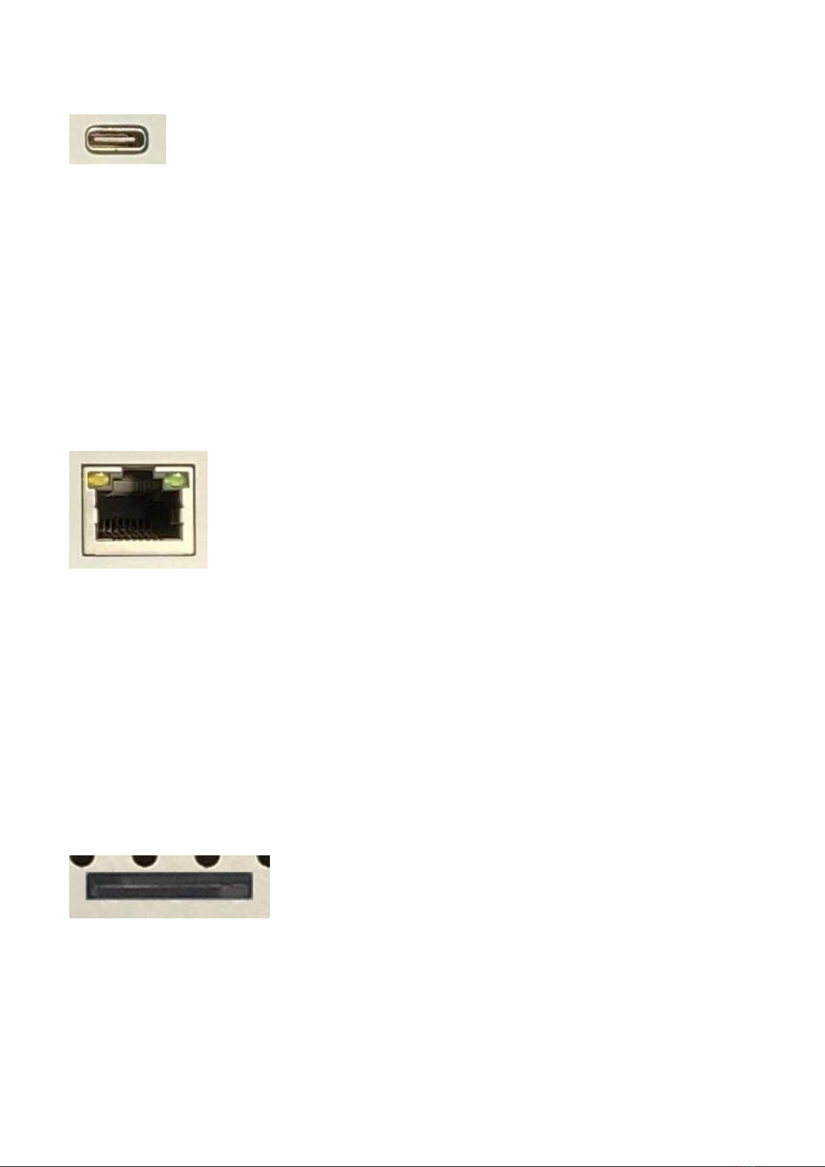
As well as one USB Type-C connector, as shown in Figure 7.
Figure 7: USB Type-C Connector
LAN Connector
The product has one channel 1000Mbit Ethernet connector, as
shown in Figure 8.
Figure 8: LAN Connector
TF Card
The product has one TF (uSD) card connector, as shown in
Figure 9, that supports a TF (uSD) card up to 32GB.
Figure 9 TF Card Connector
ATTENTION:
A TF card does not come with the product.

SIM Card Holder
There is one SIM card holder, as shown in Figure 10. To read
the SIM card data, you need a 4G/LTE module. The product has a
mini-PCIe connector inside that enables a 4G/LTE module to be
mounted. Otherwise, the holder has no usage.
Figure 10: SIM Card Holder
ATTENTION:
The 4G/LTE module is not provided by default, but can be
ordered along with the product.
Audio Connector
The CS19108R215P-C111 has one audio connector, as Figure 11
shows, as well as an internal 2W speaker.
Figure 11: Audio Connector
WiFi+BT
There is one WiFi+BT module, based on the Realtech RTL8723BU,
This manual suits for next models
1
Table of contents
Other Chipsee Industrial Monitor manuals

Popular Industrial Monitor manuals by other brands


Dynamic Displays
Dynamic Displays QES1500 Progressive Series user manual

AXIOMTEK
AXIOMTEK Dk3g4PANEL 6153-O/P user manual

ESA
ESA XM7W7 installation manual

Siemens
Siemens SIMATIC Industrial Flat Panel IFP2200 Product information

Siemens
Siemens INOX PRO SIMATIC IFP1900 Compact operating instructions

Advantech
Advantech IDK-1115WP-45FHA1 user manual