IK-TF9P1-2
5
1. CAUTIONS ON USE AND INSTALLATION
tHandling the unit.
Do not drop, jolt, or vibrate, as this may result in
damage to the unit and may cause problems.
Treat the camera cables carefully to prevent cable
problems, such as breaks in the cable and loose
connections.
tInstall the camera in a location free from noise.
If the camera or the cables are located near power
utility lines or a TV, etc. undesirable noise may
appear on the screen. In such a case, try to change
the location of the camera or the cable
wiring.Consult with a service personnel, if the
noise still appears after changing the location or
the cable wiring.
tOperating ambient temperature and humidity.
Do not use the camera in places where tempera-
ture and humidity exceed the specifications. Pic-
ture quality will deteriolate and internal parts may
be damaged.
Be particularly careful when using in places ex-
posed to direct sunlight. When shooting in hot
environments, depending on the conditions of the
object and the camera (for example when the gain
is increased), noise in the form of vertical strips
or white dots may occur. This is not a malfunction.
tWhen not using the camera for extended peri-
ods of time.
Switch the control unit off and disconnect the
power supply.
tAvoid using or storing the camera in the fol-
lowing places:
Places filled with highly flammable and corrosive
gas.
Places near gasoline, benzene, or paint thinner.
Places subject to strong vibration.
Places containing chemicals (such as pesticides),
rubber or vinyl products for extended periods of
time.
tDo not shoot intense light.
If there is an intense light at a location on the
screen such as a spot light, a blooming and smear-
ing may occur. When intense light enters, vertical
stripes may appear on the screen. This is not a
malfunction. Ghosts may occur when there is an
intense light near the object. In this case, change
the shooting angle.
tMoire
A moire pattern is an interference pattern gener-
ated when two repetitive line patterns overlap. This
is not a malfunction. Eliminating the repetitive line
patterns, or aligning the two patterns, will elimi-
nate the moire.
tHandling of the protection cap.
Keep the protection cap away from children as they
may pose a choking hazard. The protection cap
protects the image sensing plane when the lens
is removed from the camera head, do not discard.
tWhen cleaning the camera.
Unplug the power source before cleaning. Clean
with a soft dry cloth only. Do not use chemicals or
chemically treated cloths. Chemicals may damage
coatings and printed letters. When cleaning the
lens, use lens cleaning paper.
2. COMPONENTS
(1) Camera Control Unit ...................................................................................................................... 1
(2) Accessories
(a) Instruction manual ................................................................................................................... 1
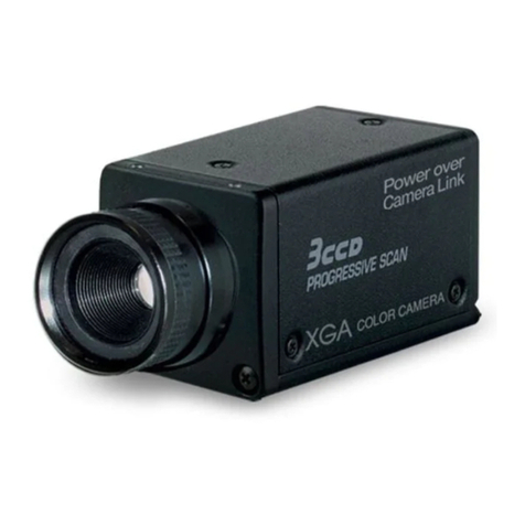
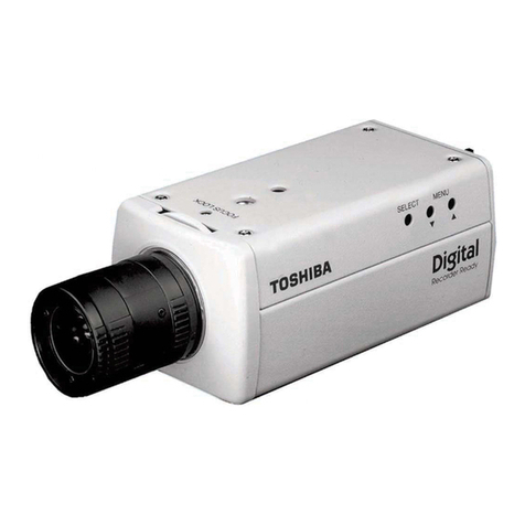
This product is a 3CCD color camera with digital video output.
( 3 ) Using the unit with external sync signal .. 33
(3. 1) H (horizontal) phase adjustment ...... 33
8.
INPUT OUTPUT SIGNAL SPECIFICATIONS ....
34
( 1 ) HD Input Specifications .......................... 34
( 2 ) VD Input Specifications........................... 34
( 3 ) Trigger Pulse Specifications .................... 34
( 4 ) External HD/VD Input Phase
Specifications .......................................... 34
9.
CCD OUTPUT WAVEFORM TIMING CHART ....
35
( 1 )
Horizontal Output Waveform Timing Chart ...
35
( 2 )
Vertical Output Waveform Timing Chart...
35
10. SPECIFICATIONS ....................................... 36
11. EXTERNAL APPEARANCE DIAGRAM ...... 37
12. BEFORE MAKING A SERVICE CALL ........ 37
4
1. CAUTIONS ON USE AND INSTALLATION ..... 5
2. COMPONENTS ................................................ 5
3. NAMES AND FUNCTIONS .............................. 6
4. CONNECTION .................................................. 7
4. 1 Standard Connection ................................ 7
4. 2 Cautions on Connection ........................... 7
4. 3 Connector Pin Assignments ..................... 7
5. OPERATION ..................................................... 8
5. 1 White Balance ........................................... 8
5. 2 Gain .......................................................... 9
5. 3 Sading Correction ..................................... 9
6. ITEMS CONTROLLED BY THE SCREEN
DISPLAY ......................................................... 10
7.
MODE SETTING BY THE SCREEN DISPLAY ..
11
7. 1 Using the Menus ..................................... 11
7. 2 Menus ..................................................... 12
( 1 ) SHUTTER (Electronic shutter) ................ 12
(1. 1) Changing the setting in
MANU mode ..................................... 13
(1. 2) Changing the setting in
SS (synchro. scan) mode ................. 14
(1. 3) Changing the setting in
E.TRG mode ..................................... 15
(1. 3. 1) Changing the setting in
1P SNR mode ............................... 15
(1. 3. 2) Changing the setting in
1P SR mode ................................. 16
(1. 3. 3) Changing the setting in
PW SNR mode ............................. 17
(1. 3. 4) Changing the setting in
PW SR mode ................................ 18
(1. 3. 5) Changing the setting in
RR mode ....................................... 18
(1. 4) Changing each setting in
AUTO mode ...................................... 19
( 2 ) GAIN (Video gain) ................................... 20
(2. 1) Changing the setting in GAIN .......... 20
( 3 ) WHT BAL (White balance) ...................... 21
(3. 1) Changing the setting in AWB
(Automatic White Balance) mode .... 21
(3. 2) Changing the setting in MANU
(Manual) mode ................................. 21
( 4 ) PROCESS .............................................. 22
(4. 1) Changing gamma correction ............ 22
(4. 2) Changing master pedestal ............... 22
TABLE OF CONTENTS
(4. 3) Changing R pedestal ........................ 22
(4. 4) Changing B pedestal ........................ 22
( 5 ) SHADING ............................................... 23
(5. 1) Changing V.SHAD. (Vertical Shading)
correction mode ............................... 24
(5. 2) Changing the manual V.SHAD. (Vertical
Shading) correction setting .............. 24
(5. 3) Changing C.SHAD. (Corner Shading)
correction mode ............................... 24
(5. 4) Changing the manual C.SHAD. (Corner
Shading) correction setting .............. 24
( 6 ) SYNC ...................................................... 25
(6. 1) Adjusting horizontal phase ............... 25
( 7 ) OPTION .................................................. 25
(7. 1) Changing serial communication
baud rate .......................................... 25
( 8 ) Returning to factory settings ................... 26
7. 3 Synchro. Scan Operation ........................ 26
( 1 ) Setting by 2H .......................................... 26
( 2 ) Setting by the frame ................................ 26
7. 4 E. TRG (External trigger) ......................... 27
( 1 ) 1P SNR
(1 Pulse Trigger Sync Non Reset) ........... 27
(1. 1) 1 Pulse Trigger SYNC-NON RESET
Picture Output Timing ...................... 27
( 2 ) 1P SR (1 Pulse Trigger Sync Reset) ....... 28
(2. 1) 1 Pulse Trigger SYNC-RESET
Picture Output Timing ...................... 28
( 3 ) PW SNR (Pulse width trigger
SYNC-NON RESET) .............................. 29
(3. 1) Pulse Width Trigger SYNC-NON
RESET Picture Output Timing ......... 29
( 4 ) PW SR (Pulse width trigger
SYNC-RESET) ....................................... 30
(4. 1) 1 Pulse Width Trigger SYNC-RESET
Picture Output Timing ...................... 30
( 5 ) RR (Reset restart) .................................. 31
(5. 1) Long Term Exposure ........................ 31
(5. 2) Input Timing Chart Example ............ 31
7. 5 Partial Read ............................................ 32
( 1 ) Partial Scanning OFF
(All pixels scanning) ................................ 32
( 2 ) Partial Scanning ON ............................... 32
( 3 ) When Partial Scanning Mode is ON ....... 32
7. 6 External Sync .......................................... 33
( 1 ) External sync signal polarity ................... 33
( 2 ) External sync frequency range ............... 33
Copyright and Right of Portrait
There may be a conflict with the Copyright Law and other laws when a customer uses, displays,
distributes, or exhibits an image picked up by the camera without permission from the copyright
holder. Please also note that transfer of an image or file covered by copyright is restricted to use
within the scope permitted by the Copyright Law.
